■研究紹介
From the European XFEL Accelerator to the International Linear
Collider
Deutsches Elektronen Synchrotron (DESY)
Wolf-Dietrich Möller
wolf-dietrich.moeller@desy.de KEK 加速器研究施設山 本 康 史
yasuchika.yamamoto@kek.jp 2018 年 2 月 1 日始めに
昨 年 , ド イ ツ 電 子 シ ン ク ロ ト ロ ン 研 究 所 (DESY) に て European X-ray Free Electron Laser (European XFEL) 計画のた めの超伝導線形加速器のビームコミッショニングが始まった。こ れは放射光実験のための加速器であるが,現在,多くの高エ ネルギー物理学者がその実現を期待している国際リニアコライ ダー (International Linear Collider (ILC)) 計画とも大いに関係 しているのである。その理由は,主線形加速器に用いられてい る超伝導空洞の技術が ILC とほぼ同じものであり,また規模と してもILC の 1/20 スケールに匹敵するものだからである。山本 は 2014~2015 年にかけて DESY に長期滞在し,European XFEL 建設の初期段階に接したことで,この計画が ILC に与え るインパクトについてよく理解している。そこで今回,当時の超 伝導空洞グループのリーダーであったWolf-Dietrich Möller 氏 に,如何にして超伝導空洞およびクライオモジュールの大量生 産を実現し,European XFEL 計画を成功に導いたのか,そして そこからILC 建設の実現に向けてどのような知見が得られたの かを概説していただくためにこの記事の作成を依頼した。本原 稿では,European XFEL 計画のための国際協力の枠組み作り, 超伝導空洞およびクライオモジュールの大量生産に伴い発生 した数々のトラブル,また達成した性能,ビームコミッショニング の状況,などを中心に解説していただいている。表1 は,ILC と European XFEL の簡単なスペックの比較を示したものである。 DESY における 1.3 GHz の超伝導空洞およびクライオモジュ ールの研究・開発について簡単に説明すると,1990 年代初め 頃に超伝導加速技術による TeV-scale のリニアコライダー (TESLA 計画)の実現を目指して,超伝導加速技術の性能向 上および価格の低下を目的とした TESLA Test Facility (後の Free Electron Laser in Hamburg (FLASH)) を国際協力の下に 建設したのがその始まりである。最終的にTESLA Test Facility ではクライオモジュールを用いたビーム加速までが実現し,超 伝導加速技術によるリニアコライダー実現への扉を開いた。 2004 年 の International Technology Recommendation Panel (ITRP) による超伝導加速技術の選択は,まさに TESLA Test Facility で実証した結果を受けてのものである。その後,計画は European XFEL へとシフトしたが TESLA 計画で築き上げた国 際協力の枠組みや達成した技術などはそのまま生かされること になり,他の研究所や会社への技術移転に大いに役に立つこ ととなった。ここで昨年11 月に ICFA による ILC の 250 GeV 開始案が承 認 さ れ た が , 本 原 稿 で 用 い て い る ILC に 関 す る 数 値 は Technical Design Report (TDR) に掲載されている 500 GeV の 場合に基づくものであることを予めお断りしておく。
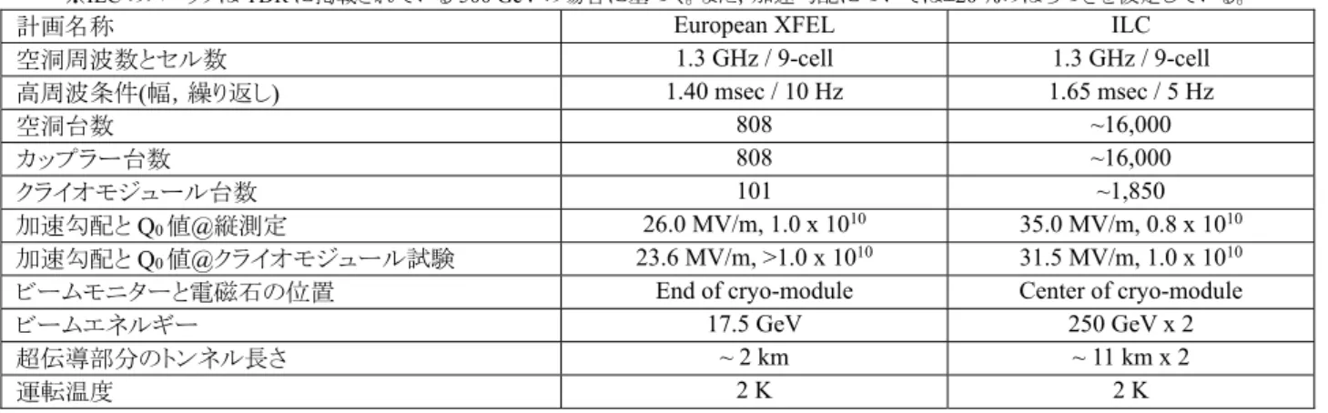
表1: European XFEL と ILC の基本スペックの比較
※ILC のスペックは TDR に掲載されている 500 GeV の場合に基づく。また,加速勾配については±20 %のばらつきを仮定している。
計画名称 European XFEL ILC
空洞周波数とセル数 1.3 GHz / 9-cell 1.3 GHz / 9-cell 高周波条件(幅,繰り返し) 1.40 msec / 10 Hz 1.65 msec / 5 Hz 空洞台数 808 ~16,000 カップラー台数 808 ~16,000 クライオモジュール台数 101 ~1,850 加速勾配とQ0値@縦測定 26.0 MV/m, 1.0 x 10¹⁰ 35.0 MV/m, 0.8 x 10¹⁰ 加速勾配とQ0値@クライオモジュール試験 23.6 MV/m, >1.0 x 10¹⁰ 31.5 MV/m, 1.0 x 10¹⁰
ビームモニターと電磁石の位置 End of cryo-module Center of cryo-module
ビームエネルギー 17.5 GeV 250 GeV x 2
超伝導部分のトンネル長さ ~ 2 km ~ 11 km x 2
1 INTRODUCTION
The European XFEL has officially started its operation on the 1st of September 2017 at Hamburg in Germany. With the delivery of 27,000 ultra-short X-ray flashes per second and peak brilliance one billion times higher than every conventional X-ray source, it will open up a wide field of completely new research opportuni-ties for scientists and industrial users.
The construction of the European XFEL started in early 2009 and involved close collaboration between Deutsches Elektronen Synchrotron (DESY), the European XFEL GmbH and many other organizations worldwide.
The superconducting (SC) linear accelerator (linac) is one of a kind in the world. With its 808 1.3 GHz cavities contained in 101 cryogenic modules (cryo-module)1 and a length of 1.7km, it is the longest SC linac in the world. It provides electrons at an energy of 17.5 GeV needed to generate the European XFEL’s X-ray flashes in a highly efficient way. As an exemplary collaboration, 21institutes from nine different countries contributed to the Eu-ropean XFEL.
The basic superconducting accelerating technology of the Eu-ropean XFEL linac has been developed since the early 1990’s by an international collaboration coordinated by the DESY labora-tory in Hamburg in order to create a TeV-Energy Superconducting Linear Accelerator (TESLA) [1], an electron-positron linear col-lider for particle physics studies. The name ‘TESLA Technology’ stands for this development. As it was realized that this SC linac technology has ideal characteristics for an X-ray free-electron la-ser, proposals for a free-electron laser as a side branch of the lin-ear collider and later as a self-standing facility were proposed by DESY and finally realized as the European XFEL. In 2004, the International Technology Recommendation Panel (ITRP) gave momentum to the newly named ILC [2]. The realization of the SC linac for the European XFEL is a big progress in the TESLA tech-nology, and at the same time a perfect example in view of the international organization of a future ILC construction. Neverthe-less its 808 cavities represent only 5 % of the total number re-quired for the ILC.
2 THE EUROPEAN XFEL
2.1 Layout and Performance
The European XFEL consists of the main components: injector, SC linac, beam distribution system, undulators, photon beam lines and instruments in the experimental hall (the layout and view shown in Figure 1). The whole facility is 3.4 km long and starts with the electron injector at the DESY site in the North West part of Hamburg, and ends in the neighbouring Federal State of Schleswig Holstein, south of Schenefeld, where the experimental hall is located. The entire facility is constructed in tunnels 6 to 38 m underground with an inner diameter of up to 5.3 m.
The injector consists of a normal conducting RF electron gun where the electrons with high bunch charge and low emittance are extracted from a solid cathode by a laser beam. Accelerated by one 1.3 GHz cryo-module, it delivers electron bunches at an en-ergy of 130 MeV. The longitudinal beam profile is improved by a superconducting third harmonic 3.9 GHz cryo-module [3, 4], while the uncorrelated energy spread is increased by a laser heater. At the end of the injector, the 600 µs-long electron bunch trains have a typical bunch charge of 500 pC.
The further acceleration of the electrons is performed in the three main sections of the main linac. The four cryo-modules in the first section are operated at a moderate gradient below the Eu-ropean XFEL design gradient of 23.6 MV/m. From the second linac section, consisting of 12 cryo-modules, the beam is ejected with a relative energy spread of 0.3 % at 2.4 GeV. In the third linac section with a length of about 1 km, the 84 cryo-modules accelerate the electron beam up to the design energy of 17.5 GeV. Between the injector and the linac sections, three bunch compres-sor sections with their dipole-magnet chicanes and further focus-ing elements and diagnostics are installed. Once the electron beam leaves the accelerator, it is directed by fast kicker magnets into one of the two electron beam lines that feed the three different undulator sections.
The availability of extreme short photon pulses (10-100 fs) and around 1012 X-ray photons in one pulse with a very high coher-ence allows experiments with ultra-fast snapshots of the dynam-ics of the atomic motion and molecular rearrangements.
Figure 1: Layout and view in the SC linac of the European XFEL. The cryo-modules are hanging from the roof whereas the RF klystrons and the electronic equipment is assembled beneath.
1 ILC では Type A(9 空洞)と Type B(8 空洞)の 2 つのクライオモジュ
ールが存在するが,European XFEL では 8 空洞が収納された 1 タイプ だけである。
2.2 European XFEL History and Organization
DESY scientists initiated an international collaboration to de-velop and test the superconducting accelerating technology for TESLA in 1992. The TESLA Test Facility (TTF) was built in or-der to demonstrate the high performance, reliability and effi-ciency of such a technology. As it was realized that this test facil-ity has ideal characteristics to realize a FEL, undulators and all necessary infrastructure were added in order to generate laser light. In 2000, the scientists of the DESY TTF generated for the first time in the world short wave laser light in the ultraviolet range (80-180 nm), using the SASE FEL principle [5]. This was the birth of the idea to use the TESLA technology for a future X-ray laser laboratory based on the TESLA technology. A technical design report (TDR) for an X-ray laser laboratory as a side branch of TESLA was published in 2002. Already in 2003, the German government decided to cover around half of the investment cost, provided the rest would be delivered by European partners. This decision led to intense negotiations on funding and participation. In July 2006, the DESY XFEL project group and the European XFEL project team, established in Hamburg through the MoU, published a TDR for the proposed European XFEL facility [6]. After the official start of the project in 2007, the international partners entrusted the construction and operation of the facility to the non-profit European X-Ray Free-Electron Laser Facility GmbH, which was founded in October. The representatives from 9 partner countries signed the European XFEL Convention and the Final Act in the Hamburg city hall as chair holders (three more partner countries signed later or will sign very soon). In the same year the construction of the European XFEL started officially.3 THE SUPERCONDUCTING LINEAR
AC-CELERATOR
3.1 The TESLA Technology
The main goal of the TESLA collaboration was to improve the performance of the superconducting cavities and at the same time reduce the cost. With the experiences from LEP, CEBAF, TRIS-TAN and HERA where superconducting cavities were operated very successfully, and newer developments from laboratories all over the world, a new infrastructure for treatment, assembly and testing was built up at DESY – the TESLA Test Facility. In this facility, every step of the cavity fabrication and treatment could be controlled and investigated, from the raw niobium material, the deep drawing and welding of cells to the final chemical treat-ment and cleaning of the active inner surface. Once the new TESLA nine cell cavity at a frequency of 1.3 GHz and optimized cell shape was designed, the fabrication was handed over to in-dustry and optimized in very close collaboration.
The infrastructure allowed extensive testing of the cavities and all ancillaries, with and without electron beam. Already the first tests showed a big step in the performance: the accelerating gra-dient reached 25 MV/m. By changing the RF surface cleaning process to electro-polishing and adding a final baking at moderate temperature (120 ºC), the achievable gradient could be improved further and reached an average of > 30 MV/m with the highest gradients over 40 MV/m.
The cryogenic experience with superconducting magnets at Fermilab, CERN and DESY led to the development of new cryo-modules containing 8 cavities including focusing elements and beam diagnostic. They are assembled in a string without addi-tional cold/warm transitions. This new technology improves the
2 DESY では基本的に超伝導空洞の性能評価のみを行っており,組立
作業については会社や他の研究所(後述)で行っている。
filling factor, saves cryogenic power and simplifies the assembly of big systems. The TESLA technology cryo-module was born and first brought to successful operation in the TTF, later renamed FLASH facility. The success of the TESLA technology was not just due to the cavity performance and cryo-module design, but also the parallel development of reliable RF power couplers, fre-quency tuners and other ancillaries. The goal of the TESLA col-laboration to reduce the cost per MV by a factor of 20 was suc-cessfully proven.
For the European XFEL, a total of 101 cryo-modules contain-ing 808 cavities were produced, which represents by far the larg-est application of superconducting RF and of the TESLA technol-ogy to date.
3.2 The International Collaboration
The European XFEL chair holders contribute to construction and cost in cash or in kind (IKC). A total of 602 M€ was contrib-uted by 79 IKC’s from 21 institutes off 9 countries with the largest IKC and other contributions from DESY. The IKC’s have the form of component delivery, secondment of staff or both. The in-tensive coordination, monitoring and integration of the IKC’s were essential to ensure a successful completion of the project.
Eight laboratories contributed to the superconducting cryo-module: DESY Hamburg in Germany, CEA Saclay and LAL, Or-say in France, INFN, Milano in Italy, IPJ Swierk and Soltan In-stitute in Poland, CIEMAT in Spain and BINP in Russia. CEA provided a completely new infrastructure for the cavity string and cryo-module assembly. The prompt availability of all cryo-mod-ule sub-components was essential for the smooth delivery of the accelerating cryo-modules to DESY for the test and final assem-bly in the tunnel. In this respect, the delivery of any sub-compo-nent in the supply chain was essential for the overall project schedule. Weekly video meetings of all contributing collaborators were conducted to follow up the schedule, and, if necessary, take action to secure the schedule.
Other important contributions were the RF high power system consisting of 27 multi beam klystrons (10 MW each) including the low level RF system (DESY), the cryogenic equipment for the SC linac (BINP Novosibirsk) and the cryogenic plant itself (DESY). The warm part consists of 3 km room temperature beam line (BINP Novosibirsk) and 700 transport magnets (Efremov In-stitute in St. Petersburg, BINP Novosibirsk, Stockholm Univer-sity). Major contributions to the electron beam diagnostic came from PSI in Switzerland, CEA in France, INR Moscow in Russia and DESY. 460 beam monitors, 64 screens 12 wire scanners and 36 toroids as well as bunch compression and beam arrival moni-tors, electro optical devices and transverse deflecting systems are essential for a state of the art beam diagnostic.
In addition to the electron accelerator equipment, many other important assignments like civil construction, electric power and cool water supply had to be coordinated.
3.3 Technology Transfer to Industry for the Cavity
Production
The European XFEL is the first superconducting RF (SRF) project where not only the mechanical fabrication of the super-conducting cavities, but also the very delicate chemical surface preparation was done by industry. The cavities were delivered to DESY ready for the performance test in vertical cryostat.2 A ma-jor effort was necessary to transfer the technology to the industry, and at the same time the vendors had to invest in the construction and commissioning of significant new infrastructure in order to
meet the stringent fabrication requirements and production sched-ule. A large team from the responsible laboratories INFN Milano-LASA and DESY consisting of about 25 experts of different fields worked in very close collaboration with both contracted companies (Ettore Zanon S.p.a. Italy (EZ) and RI Research In-struments GmbH, Germany (RI)).
The main cavity fabrication principle was the so called “build to print” strategy. Therefore, DESY provided a detailed specifica-tion for the mechanical fabricaspecifica-tion and the surface preparaspecifica-tion. Both vendors where required to extensively document each pro-duction step, and the expert team closely supervised the well-de-fined procedures and tolerances. Before starting the cavity fabri-cation, the whole infrastructure and procedures at the vendors, like clean room assembly, High Pressure Rinse (HPR), vacuum pumping and purging, and chemical polishing was tested step by step. 16 extra cavities prepared by DESY had to undergo each treatment step performed at the new infrastructure at the vendors, and were measured by DESY before and after this test cycle, be-fore the new infrastructure was proven to be ready for mass pro-duction. As a result of the “build to print” strategy, DESY ac-cepted all cavities built according to specification without perfor-mance guaranty, and took the responsibility for the recovery of poor performing cavities.
4 COMPONENT PRODUCTION AND TEST
RESULTS
As described before, many components had to be fabricated at high quality, delivered in time and tested to complete the whole European XFEL. Here we will concentrate only on a few key components of the electron accelerator: superconducting RF cav-ities, RF power coupler and the superconducting accelerating cryo-module.
4.1 Superconducting RF cavities fabrication
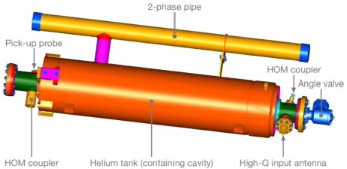
The TESLA superconducting cavity is made out of solid nio-bium and consists of 9 elliptical shaped cells at a frequency of 1.3 GHz. Two Higher Order Mode (HOM) couplers, one power coupler port and one pick-up port are located on the beam tubes. A helium tank and the 2-phase helium pipe, made out of titanium are welded to the cavity (Figure 2). The niobium material for the cavities was ordered by DESY and delivered by three companies. After an intensive quality control including scanning of the active RF surfaces at DESY3, the material was distributed equally to the two cavity vendors EZ and RI. For the RF measurements during fabrication and field flatness tuning, DESY developed and deliv-ered two dedicated semi-automatic machines to both vendors4 [7].The surface preparation is one of the most critical processes of the cavity fabrication. It determines predominantly the later cav-ity performance. For both vendors, the surface preparation started with a bulk electro polishing (EP) and a subsequent 800 ºC an-nealing. For the final polishing, two alternative recipes were used according to the company’s abilities: EZ applied a final buffered chemical polishing (BCP) of 10 µm, whereas RI applied a final EP of 40 µm5. Both vendors applied an extensive High Pressure Rinsing (HPR) with ultra-pure water at a pressure of 100 bar. Af-ter the assembly of the HOM coupler antennas, the high Q input
3空洞形状に成型する前のニオブ板の段階で,不純物の割合を渦電 流探査法によって調べ,多いものは除外している。 4電子ビーム溶接を行う前のハーフセルの段階で周波数を揃えるため にトリミングの量を自動算出する装置,および完成した9 セル空洞の各 セルの周波数を自動調整する装置のこと。
antenna and the vacuum valve in an ISO4 clean room, well-de-fined vacuum pumping and 120º C baking as final step of the preparation were applied. Close monitoring of the infrastructure and the procedures of the surface preparation was essential to achieve a high cavity performance.
Figure 2: 3-D model of the series European XFEL cavity equipped with antennas ready for performance test at DESY.
4.2 Superconducting RF Cavity Testing
A dedicated Accelerator Module Test Facility (AMTF) was used at DESY for the quality control of the cavity and cryo-mod-ule production.
The cavity’s acceptance test was divided in three parts: incom-ing inspection, cold vertical test and outgoincom-ing inspection. Since the vendors did not take any responsibility for the cavity perfor-mance, the incoming inspection took a major role in order to guar-anty a high quality of fabrication. After the verification of all fab-rication documents and the mechanical and electrical inspection (RF measurements of mode spectrum) the cavity was accepted for the vertical performance test.
In order to keep the overall project schedule, it was necessary to test up to ten cavities per week. Two vertical test cryostats with independent RF systems and six cryogenic inserts accepting four cavities per each cool down were available and used in AMTF.
All cavities were tested with assembled HOM feedthroughs and a RF input antenna with fixed coupling. The test followed a standard automated procedure, and included not only the quality values (Q0) versus the accelerating electric field (Eacc), but also the frequencies of the fundamental and the TM010 passband6. X-rays were measured inside the concrete shielding above and be-low the cryostat in order to estimate the field emission.
Starting operation in February 2013, the vertical test infrastruc-ture reached full operation in October 2013 with an average test-ing rate of approximately 40 cavities per month (peak test rate was 15 per week). The last test of the series production was fin-ished in March 2016.
4.3 Superconducting RF Cavity Test Results
The acceptance criteria was not only based on the maximum gradient Eacc ≥ 26 MV/m, but also included the quality factor Q0 > 1010 and the X-ray threshold measured below and above the cryostat. After 270 cavity test results were available, the number of necessary retreatments was analysed and the acceptance threshold for the usable gradient7 was reduced to Eusable ≥ 20 5一般的に,縦測定前の最終表面処理は電解研磨の方がより信頼度が 高く,かつより高い加速勾配まで到達できるが,European XFEL のスペ ックは23.6 MV/m であるため化学研磨でも十分である。 6 9 セルのため基本モードである TM010 も 9 個存在する。 7 Q 0値およびX 線量も許容値を満たしている加速勾配の最大値のこ と。「実際に使用可能な加速勾配」ほどの意味である。MV/m in order to optimize the number of vertical tests while still maintaining an average gradient in the cryo-module ≥ 23.6 MV/m.
There have been mainly two reasons for additional tests: the usable gradient of the cavity was considered unacceptable and the cavity had to be retreated, and there were technical issues with the cavity or with the vertical test. In Figure 3, the fractions of cavi-ties with one or more test are shown.
Figure 3: Fraction of cavities which have 1, 2, 3 or 4 vertical tests.
In Figure 4, the maximum gradient, the usable gradient and the yield curves for the cavities ‘as received’8 are shown. Since cav-ities with additional treatment are excluded, these results repre-sent best the nominal production process of the two vendors.
Figure 4: The distributions and yield curves for the maximum achieved gradient (blue) and the usable gradient (orange) for all cavities “as re-ceived”. Yield is defined as those cavities which have a gradient greater than or equal to the specified value. (The darker colour represents the overlap of the two histograms.)
As shown in Table 1, the average maximum and usable “as re-ceived” gradient is 31.4 MV/m and 27.7 MV/m, respectively. The usable gradient is about 4 MV/m lower due to low Q0 or X-rays by field emission above threshold.
One should note that about 50 % of the cavities were limited by thermal breakdown, whereas all other cavities were either lim-ited by the administrated power limit of Pfor ≤ 200 W9, i.e. the true physical breakdown limit is higher. The power limited tests were dominantly caused by a low Q0 below the acceptable threshold, which leads to a higher power consumption.
8空洞を会社から受け入れた状態のこと(再表面処理を含まない)。1 回
目の性能試験の結果だけを抽出することで製造品質の推移が分かる。
9空洞の性能試験を行う際,ケーブル損傷や高周波機器の故障を避け
るため,通常200 W 辺りで投入パワーを制限する。
Table 1: Statistics of the “as received” vertical cavity tests
Maximum Usable Average gradient MV/m 31.4 27.7
RMS MV/m 6.8 7.2
Yield ≥ 20 MV/m 92% 86%
Yield ≥ 26 MV/m 85% 66%
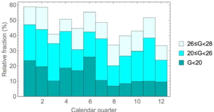
During the three years of cavity production, a clear improve-ment of the average gradient was determined. In the last 18 month of the production, the number of cavities with gradients below 20 MV/m (see Figure 5) was significantly reduced. This led in consequence to an overall reduction of retreatments and vertical tests.
Out of the 831 fabricated cavities, 313 retreatments were per-formed for a total of 237 cavities. Approximately 49 % of the re-treatments were due to unacceptable RF performance, whereas 51 % were caused by other nonconformities like e.g. vacuum leak10. It proved to be very efficient to retreat the cavities with an unacceptable RF performance first with HPR. This was especially true for cavities whose performance was field emission limited.
Figure 5: The relative fraction of cavities with a “usable gradient” in the indicated range is shown during the quarterly production of the cavities. The cavities are divided in three categories of gradient limitations “as received”: 26 -28 MV/m, 20-26 MV/m and <20 MV/m. In the second half of the production, a clear reduction of the cavities with gradiens below 20 MV/m can be seen.
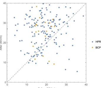
If after an additional HPR the usable gradient was still below the performance limits, the cavity was retreated with BCP. An EP retreatment was not used, because there was no experience with the cavity already welded in the helium tank. Figure 6 shows the gradient before and after the retreatment with HPR and BCP. It is clearly visible how efficient the retreatment was.
Figure 7 and Table 2 show the finally accepted maximum and usable gradient distribution and statistic of the cavities ready for the string assembly (including retreated cavities). A few cavities with a gradient below 20 MV/m were accepted for string assem-bly because of schedule reasons.
10 いわゆる「低温リーク」のこと。超流動ヘリウムは摩擦の無い液体のた
めリークする確率が飛躍的に高まる。常温でヘリウムガスを用いて行うリ ーク試験では,この種のリークを発見するのは困難である。
Figure 6: The usable gradient before and after a retreatment with High Pressure Rinse (HPR) and Buffered Chemical Polishing (BCP).
Figure 7: The final maximum and usable gradient distribution and yield of the accepted cavities for string assembly (including retreatments).
Table 2: Statistic of the finally accepted (after retreatment) cavity perfor-mance
Maximum Usable Average gradient MV/m 33.0 29.8 RMS MV/m 4.8 5.1 Yield ≥ 20 MV/m 98 % 97 % Yield ≥ 26 MV/m 94 % 79 %
As shown in Figure 8, the number of cavities with a Q0 below 1010 could be reduced by HPR, but not completely eliminated.
The superconducting cavity production and the final result for the vertical tests are summarized in the published papers [8, 9].
11高周波窓に用いられるセラミックに窒化チタンコーティングを施すこと
で二次電子放出係数が下がる。この結果,マルチパクタ放電が抑制さ れる。
Figure 8: The distribution and yield of Q0 measured at 23.6MV/m at the
first and final accepted test. Very few cavities were accepted with a Q0
value below the specified 1010.
4.4 RF power coupler
The RF high power coupler is the connecting part between the RF transmission line and the cavity; it provides the electromag-netic power to the cavity and the particle beam. In addition to this RF function, it also has to provide the vacuum barrier for the beam vacuum, and is also the connecting part between room- and cryogenic temperature. High Power Couplers (HPC) are one of the most critical parts of the RF cavity system in an accelerator.
4.5 RF power coupler fabrication
As mentioned before, the HPC was developed together with other ancillaries in the frame of the TESLA collaboration. Like for the cavity fabrication, also for the HPC the so called “build to print” strategy was applied. The HPC had to be fabricated, cleaned to the same standard as the cavity, assembled on a test stand and shipped to the coupler test facility at LAL, Orsay, France. Two suppliers were chosen: the consortium THALES, France / Research Instruments RI, Germany for 670 HPC’s, and Communication & Power Industries CPI, Beverly, USA for 150 HPC’s.
As shown in Figure 9, the HPC consists of four main parts: The cold coaxial part with the inner conductor coupling the RF power to the cavity and the warm coaxial part providing the connection to the cryo-module outer shell. Both include a cylindrical ceramic as vacuum barrier. The warm transition provides the connection to the RF source and for tuning the coupling to the cavity, a re-motely controlled motor is attached to the inner conductor.
The HPC fabrication involves many fabrication processes as machining and joining techniques with different materials, and in addition coating techniques for copper and titanium-nitride (TiN)11. In order to achieve the highest possible quality, the fab-rication was adapted to the abilities of the supplier. Therefore, an industrial study was already initiated two years in advance of the project. As a result, many improvements and simplifications from this study as well as a review of all manufacturing tolerances could be implemented for the HPC mass production.
Figure 9: Section of the European XFEL High Power Coupler model, main parts are the cold part, warm part, warm transition and tuning motor.
As the main joining technique for the HPC, metallic and ce-ramic subassemblies brazing was chosen. This technology has a good reproducibility and allowed a production in big batches. Af-ter the subassemblies were brazed, the metallic parts had to be copper plated. Due to the demanding specification in thickness and quality of the copper plating at one hand, and the complicated geometry of the components which includes different diameters, cones, bellows and big flanges, on the other hand, the copper plat-ing turned out to be the most demandplat-ing step in the whole HPC production. Many mechanical and electrical parameters were measured and documented in an extensive quality insurance pro-gram before and attendant to the mass production. An objective definition of the copper surface quality criteria for the visual in-spection was developed and agreed on between the RF- and the production experts. Using this definition, a weekly visual inspec-tion of all copper plated parts in presence of all involved parties was held.
After the final fabrication step of joining the TiN coated ce-ramic together with the metallic coaxial coupler parts by electron-beam welding, the vacuum parts were cleaned to the same stand-ard (ISO4) as the superconducting cavities and assembled in pairs of two on dedicated test stands. The coupler test stands were shipped under clean conditions packed in shock absorbing trans-portation creates from both vendors in Germany and US to LAL Orsay, France. The production rate was 8 to 10 HPCs per week.
4.6 RF power coupler testing and conditioning
LAL as the in-kind contributor for the HPCs, developed and installed a complex infrastructure for the handling and testing at a weekly rate of 8 – 12 HPCs. It includes clean rooms for assem-bly, baking ovens and a high power test stand with a 5 MW RF power source. A RF power distribution system allowed a parallel RF test and conditioning of 4 test stands (8 HPCs) at a time, as shown in Fig 10.
After an incoming inspection at LAL, consisting of visual in-spection, vacuum leak check and residual gas analysis, the two HPCs on its test stand were vacuum baked at 150 ºC in order to remove residual gasses. The following assembly on the RF power test facility was carried out again under clean conditions in a clean room. A normal RF test and conditioning cycle needed less than one week including the assembly and disassembly. The rejection rate was 13 % mainly due to unacceptable electrical discharge in the HPC, but also caused by copper plating defects.
Figure 10: European XFEL High Power Coupler test stands at LAL, Or-say, consisting of four RF power lines (shown here), each populated with two HPCs located in an ISO4 clean room.
In spite of the many difficulties during the HPC fabrication, especially in the beginning of the production, finally the quality of the accepted couplers was very high. This big success was based on and only possible due to the strong collaboration be-tween the experts at the laboratories LAL/DESY and at the com-panies involved.
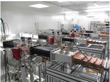
4.7 Cryo-module assembly
CEA, Saclay, France took the responsibility to assemble 100 Cryogenic Modules (CM) over two years at a throughput of 1 CM per week as an in-kind contribution for the European XFEL. The challenges were demanding:
Handle more than 10,000 individual parts per CM during integration and recognize and avoid possible non-conform-ities.
Avoid RF performance (accelerating gradient) degradations and keep the quality of all components high.
Manage many transfer interfaces with several groups at DESY, European laboratories and companies. This means to respect many different incoming quality inspections with different quality standards.
Assembling of the eight cavities to the so called ‘CM string’ is the first step in the cryo-module assembly and the most important for the preservation of the cavity performance. In this assembly step the cavities, HPCs, beam monitors, steering magnets and gate valves are connected together and the clean beam vacuum is closed. No pollution of the very sensitive SC surface of the cavi-ties is allowed; therefore it was done in an ISO4 clean room. Ded-icated procedures, special tooling and well trained personnel as well as intensive quality controls are needed to ensure the high performance of all components.
The next steps were done outside the clean room and include the assembly of all parts outside the beam vacuum, like frequency tuner, helium supply connections, thermal insulation and cryo-genic shielding. Finally the outer cryo-module vessel and the warm HPC parts are attached.
The CEA in-kind contribution was subcontracted to the work-force of the industrial contractor ALSYOM under the supervision of CEA staff.
The preparation, assembly and control work is described in 145 written procedures and first set up by CEA during the prototyp-ing phase at DESY and CEA. In a pre-series of three CMs, AL-SYOM as the executing company updated the procedures and brought them in a usable form for the French operators.
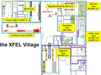
Assembly infrastructure of 2300 m2 was installed at CEA, sup-porting seven different workstations, as shown in Figure 11.
Figure 11: The XFEL Village of 2300 m2 with its different workstations
is shown. The clean room, roll out and alignment area consists of two parallel production lines in order to assure a through-put of one CM per week.
After the start of the cryo-module production in March 2014, a 5-day throughput per CM was reached in mid-October 2014 after assembly of 15 CMs. In January 2015, the 4-day throughput was established with the 25th CM.
The assembly rate benefited mainly from improvements and new developments of the clean room tooling and procedures. In addition, more human resources in the incoming inspection and quality control reduced the impact of non-conformities of com-ponent supplies on the assembly schedule.
4.8 Cryo-modules test results
The CM performance (gradient and cryogenic heat load) as a whole as well as the individual cavity performance (gradient) was measured on the three CM test stands in AMTF shown in figure 12.
In addition, the qualification of all subsystems, like frequency tuner and piezo12, quadrupole magnet, beam position monitor and HPC, was performed during these tests.
The CM performance is - with an average of 27.5 MV/m - well above the European XFEL specification of 23.6 MV/m. At the CM test stands, we were limited by available RF power to a max-imum cavity gradient of 31 MV/m. When clipping the vertical test results for better comparison also to 31 MV/m, the average vertical test result of all cavities is 28.3 MV/m13. From these num-bers, one can conclude a very small degradation of the cavity per-formance caused by the CM assembly. Besides, an improvement of the performance over time is visible in Figure 13.
In order to profit from the maximum gradient of any individual cavity, the RF power distribution system in the SC-linac tunnel was tailored for all cryo-modules.
12冷却後,空洞周波数は機械的チューナーにより1.3 GHz に調整され る。一方,高周波パワーの投入中に電磁界応力による空洞変形(ロー レンツ離調)を補整するために電気的ピエゾチューナーにより微調整が 行われる。 13縦測定では200 W のパワー制限を設けているが,クライオモジュー ル試験では31 MV/m 相当のパワーまでしか投入できず,そのパワー レベルで試験が制限されるため,両者の加速勾配を比較する際は注 意が必要である。
Figure 12: Cryo-modules in the test hall AMTF. In the foreground a fully equipped Cryo-module with the tailored wave guide distribution system attached ready for tunnel installation. The test stand shielding is visible in the background.
Figure 13: The graph shows the average cavity gradient of the vertical test (VT, blue) and CM test (CM, orange) for all CMs. For better comparison, the vertical results are clipped at 31 MV/m, the same gradient limit given by the maximum available RF power on the CM test stands.
4.9 Performance degradation and cryo-module
re-pair
The cryo-module performance degradation as described in the last chapter is caused by only a fraction of the cavities. A repair of these cavities would imply to disassemble the module and re-peat the whole cavity preparation. Since this effort could not be afforded and the average performance of 27.5 MV/m is well above the design performance we accepted the cryo-module per-formance as is14.
However, it was necessary to repair some cryo-modules for other reasons. One major problem at the beginning of the cryo-module assembly was the welding quality of the two-phase pipe connecting the cavity helium tanks (see Figure 2). This titanium lines as well as the other helium supply parts are subject to the European Pressure Equipment Directive (PED) and underlay a strict quality control by X-ray15. The welding seams of the first 10 % of the cryo-modules showed an unacceptable high number 14 クライオモジュール収納後,性能劣化が起こってしまった空洞を元
通りの性能に回復させる簡単な手段は今のところ存在しない。大量生 産が行われている傍らで,クライオモジュールを解体し,しかるべき処 置を施した後,再組立てを行う余裕は無いのが現状である。
of pores at a size > 0.5 mm and had to be repaired. This repair was already done at the XFEL village at CEA. After improving the cleanliness and an intense training of the welder, the problem was solved.
As mentioned before, the HPC is one of the most sensitive parts of the cryo-module. Due to the high complexity, the handling and assembly needs special attention. In the beginning of the cryo-module assembly, the difficulties of coupler assembly had been under-estimated. Few couplers had been damaged during han-dling in the clean room (1 %). Others suffered from bad assembly of the RF contacts16 (1 %) and were damaged during operation on the test stands at AMTF. These coupler parts were replaced during or after test in AMTF.
A major problem at the HPC appeared at a small bellow closing the warm coupler vacuum and connecting the inner coaxial part to the tuning motor. Due to a small design change at this bellow, not tested in the pre-series, the bellow formed a small RF resona-tor and was able to pick up low RF power from the nearby capac-itor. This lead to sparking and finally caused a leak in the bellow. The analysis of this problem during the ongoing production was very difficult. After the 81st cryo-module we understood the prob-lem and in consequence the RF leaking capacitors (Figure 9) of all 808 HPCs were removed and replaced by shorts17.
Few leaks appeared in the beam vacuum and the helium supply system. In four cases the beam vacuum leak and in two cases the two phase line could be repaired by only partially disassemble the cryo-module. Four cryo-modules are still under repair and have not been accepted for the tunnel installation. Since the linac was planned with one additional RF power station (including four cryo-modules), the final performance can be achieved also with only 96 cryo-modules. The repaired modules will be installed at the next major accelerator shut down.
5 LINAC ASSEMBLY
In total, 96 cryo-modules in 103 working weeks were installed in the European XFEL linac tunnel, whereas the initially pro-jected installation rate was one CM per working week.
One of the critical operations during linac assembly was the clean handling of the beam vacuum. In order to not pollute the superconducting cavity surfaces and compromise the accelerating performance, all beam vacuum operations followed the same rules as on test stands and during CM string assembly: assembly under ISO4 clean room conditions and slow pump and purge of beam vacuum. In addition, all components of the room tempera-ture beam vacuum in a range of 50 m apart from CMs were cleaned and handled under the same clean conditions as the SC components. Precautions were taken to ease the clean handling of these components: pre-assembly on girders in clean room outside of linac tunnel; pre-alignment outside the linac tunnel; beam vac-uum connections in the linac tunnel with local clean rooms.
In addition to the CMs, as main linac elements many other components had to be installed. It was a big challenge to coordi-nate the different installation groups. A dedicated planning group optimised the global process at a daily basis. Many improvements were needed for a friction free succession of installation work and in situ tests while the component transports were going on.
The complex cryogenic system which works with superfluid Helium at 2 K was completely welded in the tunnel to avoid cold leaks.
16金属同士をボルト締結する際にボルトが緩んでいると隙間が出来て しまい,そこで放電が発生する原因となる。 17 ここで述べられていることは非常に重要で,マイナーチェンジである と思って導入したアイテムが予想外のトラブルを引き起こし,結局全て のハイパワーカップラーの修理作業を余儀なくされた,ということであ
6 LINAC COMMISSIONING AND
PER-FORMANCE
The injector installation was finished already end of 2015 and the first electron beam arrived at the dedicated beam dump on December 18th 2015. During 2016, a regular 24/7 operation was established. In this time, many of the commissioning procedures, later used for the main linac, were developed, automated and tested.
The first cool down of the European XFEL linac was finished on Dec. 24th 2016. The linac commissioning started in January 2017 after the last step of the cool down procedure to 2 K was finished. Due to the consequent quality assurance procedures dur-ing installation, no cold leak in the cryogenic system was detected.
Since most of the high power RF systems had been already commissioned directly after installation, the commissioning of the low level RF together with the accelerating cryo-modules could start directly after cool down. The commissioning team in-cluded 20 experts from DESY, SLAC and HZDR working at two 8 hour shifts per day. One maintenance day per week was used to gather issues and investigate and solve them in the linac tunnel. Many of the CMs showed multipacting and required RF condi-tioning. Due to a flexible timing system allowing shifting the RF pulse of individual RF stations, parallel off beam operation and conditioning is possible.
After the first beam was accelerated to the undulators section, the photon beam diagnostics and transport beam based alignment was done.
Here are the main mile stones reached so far in 2017: April, 27th: first beam at main dump; May, 3rd: first lasing (0.9 nm);
May, 27th: beam energy close to saturation at 1mJ; June, 23rd: lasing at 1.5 Å, see Figure 14.
Currently, the European XFEL linac is being operated at 14 GeV (goal: 17.5 GeV), the flat top phase and amplitude stability is well below the European XFEL specification and the measured energy stability is ΔE/E = (0.0023 ± 0.0023) % (goal 0.01 %) [10].
Figure 14: First SASE light spot on FEL imager at 1.5Å on 2017, June 23rd.
る。大量生産を行う前に,個々のパーツ試験をどこまで行っておくかを 注意深く見極める必要がある。
In order to reach the design energy of 17.5 GeV, a task force of experts was established. The fact that four CM (32 cavities) are driven by one 10 MW multi-beam klystron with two power lines, and tolerances in the customized power distribution, is causing that a few low performing cavities can limit all other cavities in the maximum possible operable gradient18. Main challenge is to investigate all RF stations on a single cavity basis and work out solutions for operation at the maximum possible gradient.
The commissioning of the European XFEL was very success-ful, not only in respect to the schedule, but also for the achieved performance. Regular FEL user operation started in September 2017.
7 SUMMARY AND OUTLOOK FOR THE
ILC
The European XFEL is the first accelerator where 816 super-conducting cavities were fabricated, treated and assembled in in-dustry in close collaboration with the responsible national labor-atories. The TESLA technology has been successfully industrial-ized, and there are no reasons seen why this cannot be extrapo-lated to the needs of the ILC. The achieved average gradient after retreatment (28 % of the cavities were retreated) of 30 MV/m is close to the ILC specification, but a spread of 7 MV/m RMS is too large. The necessary retreatment of 28 % of the cavities is still very high. Performance degradation caused by handling, string assembly and necessary pump and purge operations is still too frequent. But it could also be shown that a string and CM assem-bly without degradation is possible. Crucial for the reach and preservation of high cavity performance are a very close cooper-ation between laboratories and industry as well as constant qual-ity assurance, qualqual-ity control and feedback. In order to profit from the high performance of individual cavities for beam acceleration, the power distribution has to be customized, which is difficult when too many cavities are powered by a single RF power source. A tunnel installation parallel to early equipment commission-ing of many systems is necessary and implies a great accuracy and a high level of organization.
The experience with the large and complex cryogenic system at European XFEL is very good and encouraging for implemen-tation at ILC.
To commission the large SC linacs of the ILC in a finite time, much more automation is necessary [11].
For the now proposed 250 GeV centre of mass ILC as a Higgs Factory, the needed number of SC cavities would reduce to about 8,000, which is a factor of 10 more than for the European XFEL. Divided by the three regions Asia, Europe and America who plan to participate in the ILC, the number of cavity mass production reduces again and becomes assessable.
Still it will be a big challenge to organize the collaborations not only between the laboratories and companies, but also between the different regions. A success requires great diligence and de-tailed planning.
まとめと
ILC 建設に向けて
多くの困難やトラブルがあったものの,European XFEL 加速 器のコミッショニングがほぼ予定通り始まったことは,ILC にとっ ても朗報である。これによりILC 建設のために必要な超伝導空18極端に性能の低い空洞が存在した場合,必要な高周波パワーも下 がってしまう。その際,個々の空洞に投入するパワーの調整裕度を十 分に持っていないと性能の良い他の空洞も低いスペックで運転せざる を得なくなってしまう。このことはILC のような高加速勾配を目指す加 洞およびクライオモジュールの大量生産が実現可能であること が裏付けられ,また多くの研究所や会社が関わる国際共同計 画をどのように推進していくのかという case study にもなった。 ILC では少なくとも 3 領域で同様の大量生産を行っていくことが 仮定されているため,建設段階では領域間同士の緊密なコミュ ニケーションも求められることになり,まさに global project と呼 ぶべきものになるであろう。 European XFEL 建設で最終的に達成された主な成果は以下 の通りである。
①
空洞性能がILC スペックをほぼ満足するものであったこと②
研究所と民間会社との共同作業による空洞ストリングおよ びクライオモジュールの組立て後に,空洞性能が大きく 下がることはなかったこと(ILC では加速勾配で 10 %の低 下を仮定しているが,European XFEL では 3 %程度であ った)③
加速器建設後のヘリウムリークがなかったこと④
ビームコミッショニングでは制御系がうまく機能したことに よりスペックの80 %まではすぐに到達したこと(さらに高い エネルギーまではもう少し時間がかかる) European XFEL 建設時に問題となったいくつかの事項につい ても述べておくことにする。これは ILC 建設時にも同様の問題 が発生するものと予想され,その際に適切に対処できるよう教 訓としておくためである。 ① クライオモジュールの不具合 ILC では空洞の生産台数には 10 %のマージンを取ってい るが,クライオモジュールについてはマージンが無い。 European XFEL ではトラブルにより結局,4 台のクライオモ ジュールがトンネルにインストールされておらず,現在も修 理・待機中である。 また,ILC では性能評価を行うクライオモジュールは全数 ではなく38 %が仮定されている。しかし,実際に European XFEL ではクライオモジュールの性能試験時に多くの問題 が見つかり,それに対処する必要があった。幸いなことに DESY には 3 つのクライオモジュール試験用ピットがあっ たため,1 ヶ所でトラブルが発生しても他の 2 つを使って乗 り切ることが出来たが,ピットが1 つしかない研究所では一 旦トラブルが発生するとすぐに滞ってしまうリスクがある。試 験用ピットをいくつ設けるのかは,クライオモジュールの大 量生産を考える上での一つポイントになる。 一方,クライオモジュールのトラブルで最も危険なのはビ ームラインのリークである。通常,空洞の連結作業時にリ ークチェックは行っているが,European XFEL では 6 台の クライオモジュールにビームラインのリークが見つかった (内1 台はゲート弁の不具合による)。ビームラインのリーク は空洞内に大量のゴミが混入してしまい,(程度にもよるが) field emission の原因にもなるため絶対に避けなくてはなら ない。実際,European XFEL ではリークを起こした 2 台のク ライオモジュールに重度の field emission が観測され,結 局,使用されていない。 38 %のクライオモジュールだけ性能試験を行うことについ ても検討の余地があると思われる。European XFEL ではク ライオモジュールの大量生産の最終段階においてもビー ムラインのリークが発生しており,この種のトラブルはある 速器において特に問題となり,クライオモジュールにおける空洞性能の 劣化を如何にして防ぐかが一つの鍵となる。割合で発生するものと仮定するのが自然である。性能試 験を行わずにトンネルに持ち込んだクライオモジュール にトラブルが発生した時に,トンネル内で対処できるなら よいが,再び地上に持ち出して修理する必要がある場合 は手間が発生する。こういったリスクもよく検討する必要が あるであろう。 ② クライオモジュールの熱負荷 European XFEL のクライオモジュールの冷却試験時に測 定された静的熱負荷の平均値が 5.6 W であり[12],これ は TDR に記述されている静的熱負荷のスペックである 1.3 W と大きく異なっている。使用しているケーブルの本 数や冷却配管に多少の違いはあるものの,基本的な構 造は同じであり,この差が生じた原因を早急に解明する 必要がある。 ③ ハイパワーカップラー (HPC) の不具合 多くの人は空洞の性能ばかりに目を向けがちであるが, カ ッ プ ラ ー の 性 能 も 同 様 に 重 要 な の で あ る 。 実 際 , European XFEL では空洞よりもカップラーに多くのトラブ ルが発生しており,カップラーにも依然として多くの課題 が残されているということが判明した。その内の一つは Möller 氏も指摘しているように銅鍍金のクオリティである。 ④ トンネルインストール後のトラブル 2008 年に起こった LHC での半田付け不良によるトラブル は多くの人々の記憶に新しいと思われるが,European XFEL でもヘリウム配管における圧力試験中に機械的ク ラッシュが発生しており,ILC でもこの種のトラブルには十 分に注意する必要があるであろう。 ⑤ 空洞へのパワー分配の最適化 European XFEL でもまだ調整中であるが,クライストロンか ら各空洞へ供給される高周波パワーの最適化がなされな いと,空洞性能を最大限引き出すことが出来ない。ILC は 最高エネルギーを目指す加速器であるため,パワー調整 は柔軟に行えるよう備えておく必要がある。
ACKNOWLEDGMENT
We like to thank all partners from the different institutes and industries for their outstanding cooperation during the construc-tion of the European XFEL. The Informaconstruc-tion and data in this ar-ticle are from many different sources, which are too many to ref-erence all of them here. We thank all authors and apologize to the unnamed authors.
Thanks also the JAHEP journal for the possibility to publish this article.
謝辞
最後に私のドイツ滞在中にお世話になった方々に対し改め て御礼を申し上げたい。まず,私の滞在手続きや滞在費の工 面などを受け持っていただき,また本記事の執筆も快く引き受 けてくださった Wolf-Dietrich Möller 氏に格別の感謝を申し上 げます。また,同じグループで一緒に仕事をし,大いに助けて いただいたDetlef Reschke 氏,Nick Walker 氏,Jacek Sekuto-wicz 氏,Jens Iversen 氏,Axel Matheisen 氏,Denis Kostin 氏, Alexey Sulimov 氏,Jan-Hendrik Thie 氏,Mateusz Wiencek 氏, にも感謝申し上げます。滞在中の雑務を担当してくださった Katrin Lando 氏,Steffi Killough 氏,Michal Abramova 氏にも 感謝申し上げます。滞在中のアパートの大家さんであった Jürgen Aust 氏には細かな配慮をしていただき特に感謝申し上げます。ここには書ききれませんでしたが,他にも多くの方々に 助けられました。ありがとうございました。
References
[1] B. Aune et al., PRST-AB, 3, 092001 (2000). [2] http://www.linearcollider.org/ILC
[3] C.G. Maiano et al., PRAB, 20, 042005 (2017). [4] P. Pierini et al., PRAB, 20, 042006 (2017).
[5] J. Andruszkow et al., PRL, 85, 18, pp. 3825-3829 (2000). [6] M. Altarelli et al., DESY Report No. 2006–097, 2006. [7] D. Reschke et al., PRST-AB, 13, 071001 (2010). [8] W. Singer et al., PRAB, 19, 092001 (2016). [9] D. Reschke et al., PRAB, 20, 042004 (2017). [10] M. Omet, private communication, to be published
[11] N. Walker, “The European XFEL Experience and Lessons Learned”, LCWS2017, Strasbourg, France.
[12] B. Petersen et al., “Serial testing of XFEL cryomodules”, CEC/ICMC2017, Madison, WI, U.S.