Yasushi Ohkawa and Koichi Inoue (JAXA)
HTV(
こうのとり
)は,
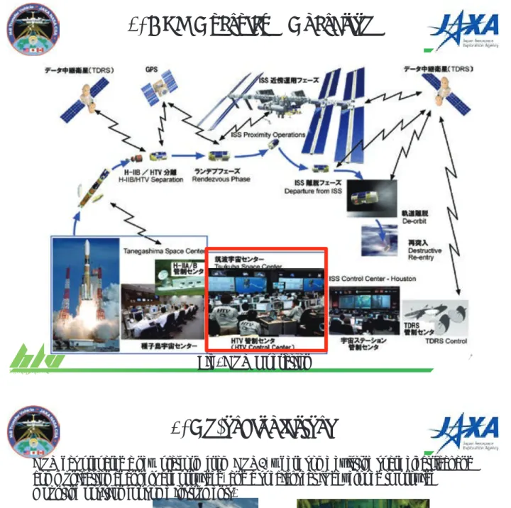
ISSへ物資を補給する宇宙機であり、
2009年から
2013年にかけて
HTV1~4号機の
4機連続ミッション成功を実現している実績を持つ。本実績に基づき、
HTV4号機より軌道上プラットフォームを 整備して、機器開発ユーザーに軌道上実証機会を提供している。
HTV6号機では、デブリ除去技術の有力 な候補である導電性テザー技術の実証実験を行う計画であるが、実験構成機器は
10個に及ぶ為、軌道上 プラットフォームの拡張が必須である。本発表では、実験に向けた軌道上プラットフォームの整備状況、及び、
実験構成機器の搭載に向けた各種インタフェース試験状況を報告する。
The H-II Transfer Vehicle (HTV) is Japan’s unmanned cargo transfer spacecraft that delivers cargo/supplies, and HTV1 through HTV4 completed the mission successfully. Based on the flight experiences, a on-orbit platform function is developed to provide the demonstration chance to users from HTV4. Currently, ElectroDynamic Tether (EDT) technique is planned to be demonstrated in HTV6, which is a promising candidate of debris removal device. The number of its instruments is as many as ten, and then the platform function has to be extended. The presentation shows its developement status, including the interface test plan and a part of results with experimental instruments.
1 1
ᑟ㟁ᛶ䝔䝄䞊ᐇドᐇ㦂䛻ྥ䛡䛯 HTV 㛤Ⓨ≧ἣ
HTV Development Status for ElectroDynamic Tether Experiments
䕿㎷⏣㍜䚸ⴱすᚭ䚸୰㔝ⱥ୍㑻䚸᳜ᯇὒᙪ䚸 Ἑᮏ⪽⨾䚸ᕝᜤᚿ䚸ୖᾈ୍ (JAXA)
䕿 Daisuke Tsujita, Toru Kasai, Eiichiro Nakano, Hirohiko Uematsu, Satomi Kawamoto, Yasushi Ohkawa and Koichi Inoue (JAXA)
➨䠒ᅇ䝇䝨䞊䝇䝕䝤䝸䝽䞊䜽䝅䝵䝑䝥 2014.12.17 䡚 19
䠜 JAXA ㄪᕸ
2
1. Purpose
z The H-II Transfer Vehicle (HTV) is Japan’s unmanned cargo transfer spacecraft that delivers cargo/supplies, and HTV1 through HTV4 completed the mission successfully.
z Based on the flight experiences, a on-orbit platform function is developed to provide the demonstration chance to users from HTV4.
z Currently, ElectroDynamic Tether (EDT) technique is planned to be demonstrated in HTV6, which is a promising candidate of debris removal device. The number of its instruments is as
many as ten, and then the platform function has to be extended.
z The presentation shows its development status, including the
interface test plan and a part of results with experimental
instruments.
H-II Transfer Vehicle
3
• HTV-3: July. 21 to Sep. 14, 2012
• HTV-4: Aug. 4, 2013 to Sep. 7, 2013
• HTV-5 to -7: Planed in 2015 to 2017
Almost yearly launch can be expected … Good mother spacecraft for demo mission!
Picture (C)NASA
H-II Transfer Vehicle
H-II Transfer Vehicle
4
2. HTV Overview –Configuration–
Dimensions Length: 9.2 m Diameter : 4.4 m Total mass
full loaded 16.5 ton Launch
Vehicle H-IIB launch Vehicle Target orbit Altitude:
350km~460km Inclination: 51.6deg Cargo
capability 6 ton in total Press. Up to 5.2 ton Un-press. Up to 1.5 ton Propulsion
system Four 500N main engine
Twenty eight 120N RCS thrusters HTV Characteristics
Unpressurized ULC
Logistic Carrier Pressurized PLC
Logistic Carrier
Avionics AM
Module
Propulsion PM
Module
H-II Transfer Vehicle
Fig. HTV Operation
52. HTV Overview –Operation–
6
3. On-orbit platform
Special Seat The platform to be in
replacement of a SAP
Fig. Platform position
HTV has prepared a new platform from HTV4, where some existing spare electrical and communication channels are provided, and a special seat is developed to provide
mounting position for some instruments.
Item Content
Electrical IF 50V power supply, On/Off commands, some analog telemetries Mechanical IF Mounting on the special seat
Thermal IF Isolated thermally from the HTV structure Mass Less than approx. 5kg
Comm with Ground Communication with HTV Operation Control System via HTV.
Table. Platform Interface
H-II Transfer Vehicle
Fig. The electrometer overview
7The platform will be used by a similar instrument in HTV5.
fasners
HTV IF Connector
TREK-3G Body Probe
MLI
Silver teflon
SCM
ATOTIE-mini
TREK-3G
electrometer
H-II Transfer Vehicle
8
4. ElectroDynamic Tether (EDT) experiments plan
[Candidate for HTV6]
As larger scale experiments, EDT
experiments, are planned in the extended platform on HTV6.
[What is EDT]
An electrodynamic tether is a promising candidate of deorbit propulsion for future active debris removal systems because of its simplicity, high efficiency, easy
attachment to debris, and no need of thrust vectoring. Since the electrodynamic tether utilizes Lorenz force by interaction between current on tether and the geomagnetic field to generate deorbiting force, the propulsion system needs neither propellant nor high electrical power in principle
e e e
e e
e Electron emission
Electron collection
Drag force by Lorenz force ( I
㽢
B )Geomagnetic field (B)
Electric current( I ) Flight
direction
Earth
Fig. The EDT Principle End-mass
End-mass
H-II Transfer Vehicle
9 9
[Configuration]
The endmass is ejected from the HTV to deploy the tether whose length is approximately 700m. Tether current is driven 10mA at the maximum by using electron emitter on the HTV and the direction from nadir to zenith, so that Lorenz force applies on the opposite flight direction.
End-mass
e- e-
e- e- Tether
(700m)
Electron emitter
HTV
Current (max 10mA)
Fig. The Experiments configuration
experiments plan
10 10
4. ElectroDynamic Tether (EDT) experiments plan
reel mech
End-mass
Tether
EmitterEle End-mass Hold&
Release Mech DHU䠋
PCU
Equipments on HTV
Electrometer/
Electrostatic probe
HTV
Magnet Sensor Camera
POWER COM/DH
Ele Emitter Cont Tether Sep
Reflector Mech
EDT Instruments 18
RVS
Fig. System block diagram
[System block diagram]
The special characteristic of EDT on the HTV is that the endmass motion is monitored by HTV Rendezvous Sensor (RVS), which is used in approaching International Space Station (ISS). First concept said that GPS monitors the endmass position and transponder
transmits the data to the HTV. In that case, the endmass needs batteries / solar array panels / power control unit for the GPS and transponder, at least, which indicates very complex system. However, HTV RVS solves the problem. Only the reflector is needed on the endmass, so that it greatly contributes to simplifying the system.
H-II Transfer Vehicle
11 140 ~ 150 km altitude
( ༡⦋ 45 deg, 㧗ᗘ 120
ISS
DSM1/DSM2: Descending Maneuver DOM1/2/3: Deorbit Maneuver ISS orbit (Altitude: 350 ~ 460 km)
Parking orbit Reentry orbit
Reentry flight - path angle
Reentry interface point South latitude: 40deg, Altitude: 120km 1. ISS departure
2. Descent to parking orbit 3. Awaiting a timing of reentry 4. Reentry
DSM1
DSM2 DOM1
DOM3 DOM2
Atmosphere
AE KOS
5 km nominal 20 km or MORE, Removed tether not to reenter to AE Conduct EDT Demo at Parking Orbit (for 1 week)
Cut tether before DeOrbit Maneuver 1 (DOM1)
H-II Transfer Vehicle
12 DH 1
DHU䠋PCU
Power Unit
LP-POM
Power ON/OFF
Command
Endmass Hold & Rls Mech
FECC/FECG/FECH
mass End-
Power Tele Command UPLC
Avionics Module
Propulsion Module
ON/OFF Status
Tether Cutting Mech-A
RVS-A RVS-B DH 2
CMR/MAGS
UPLC Controller-A
Tether Cutting Mech-B
CCSDS CompB Serial Comm
CCSDS CompA
Track
ON/OFF
Command Telemetry
Power TeleCommand Tele
Command Power
TeleCommand TeleCommand
Power Modified
KITE Comp
5. HTV development plan for the experiments
UPLC Controller-B
Extended parts
H-II Transfer Vehicle
13
Fig. UPLC Overview
5. HTV development plan for the experiments
End-mass Hold & Release Mech(EHR)
MAGS
CMR Data Handling Unit(DHU)/PCU
UPLC provides the new installation area as the extended platform.
Fig. HTV development plan overview 14
Field Emission Controller Module (FEC module)
Langmuir Probe POtential-Meter (LP-POM)
5. HTV development plan for the experiments
Remark)MLI is not shown
PM provides a additional installation area as the extended platform, such as FEC
module position.
H-II Transfer Vehicle
15 PLC
UPLC
AM PM
䞉ULCC(EM)䡚TCM (EM) IF test : Finished 䞉ULCC(PFM)䡚 TCM(PFM) IF test : Around spring in 2015.
䞉 Functional test for the Instruments on UPLC : Around spring in 2015
Launch Site Operation Factory
Instruments on PM - FEC Module
- LP-POM Function test
Y-0
Transport/Storage
Functional test for Instruments on Assembled HTV
䞉AM(EM)䡚DHU/PCU㻌 (EM) IF test : Finished 䞉AM(EM) 䡚LP-POM IF test : Around spring in 2015.
Instruments on UPLC 䡚AM&PM IF test
The instruments interfaced directly to HTV are planned to have IF test before shipping to the launch site.
H-II Transfer Vehicle
㻴㼀㼂㻢㻌㻼㻹㻌㼜㼕㼏㼠㼡㼞㼑㼟㻌
16㻴㼀㼂㻢㻌㼁㻼㻸㻯㻌㼜㼕㼏㼠㼡㼞㼑㻌
㻱㻴㻾㻌㻼㼛㼟㼕㼠㼕㼛㼚㻌㻰㻴㼁㻛㻼㻯㼁㻘㻌㻹㻭㻳㻿㻌 㻼㼛㼟㼕㼠㼕㼛㼚㻌
㻸㻼㻙㻼㻻㻹㻌 㻼㼛㼟㼕㼠㼕㼛㼚㻌
㻲㻱㻯㻌㻹㼛㼐㼡㼘㼑㻌 㻼㼛㼟㼕㼠㼕㼛㼚㻌
5. HTV development plan for the experiments
H-II Transfer Vehicle
17
6. Summary
z The presentation shows HTV development status for ElectroDynamic Tether Experiments.
• The extended platform on HTV is being manufactured for EDT experiments.
• Some interface tests has been done and are planned.
z We would like to execute the plan steadily and provide the flight chance and, finally contribute solving the space debris problem.
デブリ除去衛星システムサイジング検討<その 2>
Debris removal satellite system sizing examination #2
○廣田 賢治,渡辺 順一郎
(TECS),桑尾 文博,大塚 聡子
(NEC), 河本聡美,池内 正之
(JAXA)○Kenji Hirota, Junichiro Watanabe(TECS), Fumihiro Kuwao, Akiko Otsuka(NEC), Satomi Kawamoto, Masayuki Ikeuchi(JAXA)
デブリ除去衛星の開発においては軌道上実証を行い、実用化衛星の開発を目指すというロードマップが立 てられている。実証を目指す上で、衛星システムはシンプルかつミニマムな設計を検討した。本報告では、軌 道上実証衛星のシステム設計結果を報告するとともに、実用化に向けた課題を検討する。
In the roadmap for developing the active debris removed (ADR) satellite, the demonstration satellite will be launched before the ADR satellite. As the verification is a top priority, the demonstration satellite is minimum designed. The system of the demonstration satellite will be reported and issues to develop the ADR satellite will be discussed.

![Fig. System block diagram [System block diagram]](https://thumb-ap.123doks.com/thumbv2/123deta/6798278.2227342/6.892.106.785.87.1011/fig-system-block-diagram-system-block-diagram.webp)

