A Thesis for the Degree of Ph.D. in Science
Electron paramagnetic resonance of photoexcited triplet states of oxygen-vacancy centers in silicon
March 2012
Graduate School of Science and Technology Keio University
Akhtar Mohammad Waseem
Abstract
Spin-based quantum computation is one of the most ambitious applications of spin- tronic where the electron and/or nuclear spins are employed as quantum bits (qubits).
In the scheme of semiconductor silicon-based quantum computing, electron spins and nuclear spins of phosphorus donors and nuclear spins of
29Si have attracted much atten- tion as candidates for qubits. However, neither physical processes to transfer quantum information into and out of a particular spin qubit nor methods to exchange information between spin qubits have been established.
The present thesis shows that the presence of photoexcited triplet electron spins of oxygen-vacancy centers (SL1 centers) in silicon establishes a novel way to induce spin flip-flops of the triplet spins with phosphorus electron spins even in the absence of electromagnetic excitation field. Moreover, SL1 center is shown to be an excellent center to transfer quantum information into and out of
29Si nuclear spin qubits.
The thesis is composed of six chapters. Chapter 1 is an introduction which includes the motivation and the detail description of the spin systems utilized in this work.
Chapter 2 provides the basic principles of magnetic resonance techniques employed in this work.
Chapter 3 shows the spin dependent recombination processes via phosphorus donor states and SL1 triplet states in silicon detected by the change in the photoconductivity of samples. This corresponds to electrically detected magnetic resonance (EDMR) of electron and nuclear spin states of phosphorus and SL1, i. e., electrical readout of spin qubit states in silicon. Furthermore electrical detection of cross relaxation (EDCR), flip- flops between phosphorus bound electron spins and SL1 triplet spins, is shown. When the Zeeman splittings of the dipolar coupled phosphorus electron and photoexcited triplet electron spins are made equal by appropriate tuning of the external magnetic field, they undergo flip-flop transitions which change the overall recombination of the photoexcited carriers and thus changing the photoconductivity of the sample.
Chapter 4 investigates the lifetime of the photoexcited triplet SL1 centers and their
interaction with the nearest-neighbor
29Si nuclear spins using pulsed electron paramag-
netic spin resonane (pEPR). While the population rates of the three triplet levels are
almost equal, the decay rate from each triplet level to the ground singlet state is found
to be different leading to
≈100%spin polarization in about 1.5 ms after creation of
the photoexcited states by the laser pulse. The electron spin echo envelop modulation
ii reveals the hyperfine coupling of the triplet electron spins with the nearest-neighbor nuclear spins of
29Si (I =1/2).
Chapter 5 describes a proof-of-concept operation of
29Si nuclear spin quantum mem- ory in silicon. The coupling between the highly polarized triplet electron spins and
29Si nuclear spins facilitate the transfer and storage of the coherent state of the triplet elec- tron spins in the nuclear spin degrees of freedom using a series of resonant microwave and radio frequency pulses in the pulse electron nuclear double resonance (pENDOR).
We found nuclear storage time of nearly 5 ms which is close to the previously reported
T2nof 5.6 ms for
29S.
Finally summary and outlook are provided in Chapter 6.
Acknowledgements
It has been nearly three years in Itoh group and would like to acknowledge most of the people who directly or indirectly contributed towards the completion of this thesis.
I sincerely thank my supervisor Professor Kohei M. Itoh for giving me an oppertunity to pursue this work under his guidence and for the fruitful discussions that we had on the topics related to this work. His useful comments and criticism has certainly helped me in becoming a better researcher and motivated me to keep the pace of my research.
Well, all I can say is that he was the person without whose support, it would have been difficult to achieve this feat. The second person who comes to mind when i talk about guidence in my PhD is certainly Professor Leonid Vlasenko. My interaction with him really helped me in understanding my research and get some exciting results. I would also like to thank Dr. John Morton of Oxford University who really helped me in the latter part of my PhD work. I am really greatful to him for giving me the chance to work in his group and perform some exciting experiments. I also learned a lot about writing articles and about some experimental techniques.
I am really thankful to the Professor Eiji Ohta, Professor Junko Hayase, Professor Yoichi Kamihara and Professor Leonid Vlasenko for reveiwing this research work and for their kind comments for improving the thesis.
I would like to thank Aizawa-san for her unconditional support and always helping me in preparing documents those were in japanese. I also thank Prof. Uematsu for discussions and for his help while performing some ion implantation simulation.
My special thanks to Dr. Hiroki Morishita for teaching me the experimental tech- niques used for electrical detection of magnetic resonance. I am highly oblige to Dr.
Takeharu Sekiguchi for taking out time for lengthy discussions that helped me a lot in understanding the various pulse sequences utilized in this work. I would also thank Dr. Vasilea Filidau for helping me in my work at Oxford University and for her warm hospitality during my visit to UK.
Although few of the group members were directly involved in my project, their research activities, spirits, opinions, and other right things affected me in several ways, and all the other past and present group members are worthy of acknowledge- ments. A sincerely acknowledge the support from the laboratory members namely, Dr.
Satoru Miyamoto, Dr. Hiroki Morishita, Dr. Mohammad Rizwanur Rahman, Toy-
iv ofumi Ishikawa, Yoko Kawamura, Itahashi Tatsumasa, Shinichi Tojo, Hiroyuki Tezuka, Masashi Hirose, Nao Harada, Miki Nganawa, Kei Yoshizawa, Shinchan Hong Agung, Luis Jou Garcia, Rii Hirano, Katsuhiko Naito, Go tsuchiya, Yuri Sakuma, Kei Koga and Tomoya Arai, all of whom really made my research journey a memorable one. One person who has always been very helpful, supportive and really entertainer is Matsuaka Takashi, a final year master student at our laboratory. I wish him and all others a very best for their future endeavors.
I am really grateful to Dr. Mohammad Rizwanur Rahman and Dr. Vijay Raj Singh for making the stay in Japan a memorable one. Finally, I would like to thank my friends and my family who supported me all along these years. My family has been a really backbone for me throughout my life and their love and support has encouraged me to overcome the difficulties throughout this research life. A special thanks to my fiance whose unconditional support has motivated me and helped me in focusing on my work.
On the financial aspect, this work was supported in part by Grant-in-Aid for Scien-
tific Research and Project for Developing Innovation Systems by MEXT, FIRST, Keio
G-COE and JST-EPSRC/SIC (EP/H025952/1). I am thankful to them for funding this
research.
Contents
1 Introduction 1
1.1 Background and motivation . . . . 1
1.1.1 Spin based quantum computer . . . . 1
1.1.2 Phosphorus (
31P) in silicon . . . . 3
1.1.3
29Si nuclear spin in silicon . . . . 5
1.2 Triplet state: Two interacting electrons . . . . 6
1.2.1 Photoexcited Triplets . . . . 9
1.2.2 Unique properties of photoexcited triplets . . . . 10
1.3 Photoextied triplets in silicon: SL1 centers . . . . 12
1.4 Organization of thesis . . . . 15
Bibliography 16 2 Magnetic Resonance 20 2.1 Introduction . . . . 21
2.1.1 Electron magnetic moment and its interaction with magnetic field 21 2.2 Pulsed Electron Paramagnetic Resonance . . . . 25
2.2.1 Hahn echo method . . . . 25
2.2.2 Spin-Spin Interaction . . . . 26
2.3 Electrically detected magnetic resonance . . . . 29
Bibliography 32 3 Spin dependent recombination processes in phosphorus doped
γ- irradiated silicon 33 3.1 Electrically detected magnetic resonance . . . . 34
3.1.1 Introduction . . . . 35
3.1.2 Experimental . . . . 36
3.1.3 Results and discussions . . . . 36
3.1.4 Conclusion . . . . 40
3.2 Electrically detected cross relaxation . . . . 41
3.2.1 Introduction . . . . 42
3.2.2 Experimental . . . . 44
Contents vi 3.2.3 EDMR and EDCR spectra . . . . 45 3.2.4 Angular dependence of EDCR line positions . . . . 48 3.2.5 Model for the observed photoconductivity change under cross re-
laxation . . . . 50 3.2.6 Conclusion . . . . 54
Bibliography 55
4 pEPR study of SL1 center 58
4.1 Lifetime of photoexcited triplets:SL1 centers . . . . 59 4.2 Electron spin echo envelop modulation . . . . 64 4.3 Conclusion . . . . 69
Bibliography 70
5 Coherent storage of photoexcited triplet states using
29Si nuclear spins
in silicon 71
5.1 Introduction . . . . 72 5.2 Experimental . . . . 72 5.3 Coherent state transfer between photoexcited triplets electron spin and
29
Si nuclear spin in silicon . . . . 74 5.4 Conclusion . . . . 78
Bibliography 79
6 Summary 81
6.1 Summary . . . . 81
Chapter 1
Introduction
1.1 Background and motivation
1.1.1 Spin based quantum computer
The massive increase in computational power of contemporary digital computers (clas- sical computers) is a direct result of the successful drive to build devices on smaller and smaller scales. However, there is a physical limit to this process of miniaturization and soon a stage will be reached when we will have systems working on atomic scales governed fully by quantum phenomena. This leads to the idea of building a quantum computer based entirely on the quantum phenomena [1]. Computers whose operation is based on the fundamental principles of quantum mechanics promise to outperform even the fastest conceivable classical computers [2]. The two main elements for the realization of these quantum computers are
1)data representation by quantum bits (qubits) and
2)quantum gates to manipulate qubits to perform logical operation. A classical computer has a memory made up of bits, where each bit represents either a state
|ψi=
|0ior
|ψi=
|1istate . However, its counterpart QCs utilizes the quantum two level systems as quantum bits (qubits) where the qubits can be in any of the valid superposition states of
|0iand
|1i, i.e.
|ψi=α|0i+
β|1i. Such a vector can be visualized on the Bloch sphere shown in Figure 1.1 as
|ψi=
cos(θ/2)|0i+
eiφ/2sin(θ/2)|1i.
The corruption of this quantum state can be due to: the corruption of
θwhich is also known as spin lattice relaxation time
T1and also due to the corruption of
φknown as decoherence time
T2. In order to harness the enormous capability of a QCs we need to look for physical system where the qubits can be scaled, initialized and manipulated on a much faster time scale than its decoherence time. And finally, the read out of the final state of the qubits should be feasible.
So far there has been many quantum system proposed as a qubits. Prominent exam-
ple includes atoms in cavities, trapped ions and liquid state nuclear magnetic resonance
(NMR) where the first few quantum system which attracted researchers worldwide for
the realization of QCs [3, 4, 5]. However, all the above mentioned system face the prob-
1.1. Background and motivation 2
Figure 1.1: Bloch sphere- Bloch sphere representation of a vector.
lem of scalability. The requirement for the scalability motivated researchers to propose solid state quantum computer based on electron spin qubits (“up" spin and “down" spin:
two level quantum system). In that regard, electron confined to GaAs quantum dots have been proposed [6]. But due to the interaction with the
100%nuclear matrix and the spin-orbit interactions in these systems, electron spin dephases on a much faster time scale.
Silicon based quantum computer has an advantage of the well developed semicon- ductor technology that would be needed for integration of devices. The added advantage of silicon lies in the isotopic engineering which allows having an isolated spin free bath for quantum system. There has been two very promising proposals in silicon: 1) Kanes quantum computer [7] and 2) All silicon quantum computer [8, 9].
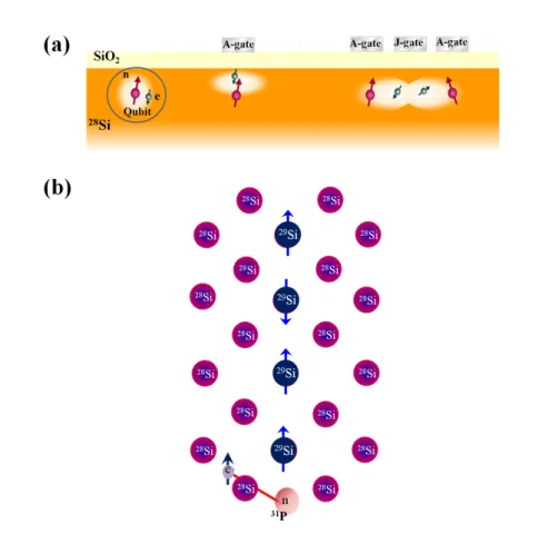
1) Kanes quantum computer: It was Bruce Kane in 1998 who proposed an idea of utilizing an array of phosphorus atoms in silicon as qubits (shown in Figure 1.2(a)).
Phosphorus is a hydrogenic donor in silicon having an electron spin
S=1/2 and a nu-clear spin
I=1/2. In the proposed architecture for QC, individual donors could be addressed by tuning the hyperfine interaction between the electron and nuclear spin with application of electrostatic bias directly above the donor position (A-gate). This changes the energy levels of the donor spin states and thus making the donor resonant or non-resonant with the globally applied radio frequency field. Two qubit operations are performed by tuning the exchange interaction between the donors with J-gate placed between the A-gates.
2) All silicon quantum computer : Silicon has three stable isotopes namely,
28Si,
1.1. Background and motivation 3
Figure 1.2: Quantum computer model- (a) Kanes quantum computer. (b) All silicon quantum computer.
29
Si and
30Si, out of which only
29Si has a nuclear spin
I=1/2. The proposed all siliconquantum computer utilizes the linear chain of these nuclear spins as qubits embedded in the spin free matrix of
28Si (Figure 1.2(b) ). With application of large magnetic field gradient the nuclear spins in the linear chain can be addressed selectively by resonant radio frequency pulses. The readout can be done using magnetic resonance force mi- croscopy where the nuclear spin state couples to the vibrational mode of the cantilever.
The other method for readout could be the use of hyperfine coupling of the nuclear spins with the electron spins of donors.
1.1.2 Phosphorus (
31P) in silicon
Phosphorus (
31P) in silicon is one of the most studied group V donors in silicon [10, 7].
31
P has an electron spin
S=1/2 and a nuclear spin I=1/2. At helium temperature theelectron is bound to the phosphorus atom and the Hamiltonian for such a system in the
presence of external magnetic field can be written as:
1.1. Background and motivation 4
HSi:P=geµBBSz−gnµnBIz+aS·I,
(1.1) where
Sand
Iare electron and phosphorus nuclear spins, respectively. Here
geµB/2π~≈ 28GHz/T and
gnµn/2π~ ≈ 17.2MHz/T are given by electron and nuclear
g-factors ge ≈ 1.9985and
gn ≈ 2.2632, respectively.The hyperfine constant is a/2π~ ≈ 117.5MHz.
The third term represents the hyperfine interaction between phosphorus electron and nuclear spins, respectively. In high field regime, the Zeeman terms are much greater than the hyperfine term and we have pure states represented as
|1i = |↑↑i,
(1.2)
|2i = |↑↓i,
(1.3)
|3i = |↓↑i,
(1.4)
|4i = |↓↓i,
(1.5)
Si:P quantum system can be thought of as a two qubit quantum computer: for example, the controlled NOT operation where the electron spin flips conditioned by the state of the hyperfine coupled nuclear spin can be realized by exciting the EPR transition
|↓e↑ni : |↑e↑ni, the SWAP operation [11] can be realized by exciting thetransition
|↓e↑ni : |↑e↓ni. Other significant advantage is the isotopic engineering ofsilicon allows to have well isolated donors in silicon due to which long coherence time of nearly 60 msec for
31Pelectron spins and 2 sec for nuclear spin (limited by the spin relaxation time of the bound electron) has been measured [12, 11]. Add to this the recent experimental demonstration of entanglement between the coupled electron- nuclear spin of phosphorus in silicon, one of the essential requirements for quantum information processor [13].
However, the successful implementation of phosphorus in silicon for quantum com-
puting application will require readout of single spin states. However, current EPR
spectrometer has a much lower sensitivity and would be difficult to monitor single
spins. But highly sensitive electrical method, electrically detected magnetic resonance
(EDMR), could be employed for the readout of small number of spins. In this thesis
we will demonstrate that the
γ-irradiation defects in silicon can be used to probe elec-
tron and nuclear spin of phosphorus in silicon by EDMR spectroscopy. We will further
demonstrate the electrical detection of cross relaxation in silicon due to the flip-flop
1.1. Background and motivation 5 transition between the dipolar coupled electron spin of phosphorus and photoexcited triplet SL1 center.
1.1.3
29Si nuclear spin in silicon
Crystalline silicon is the most widely used semiconductor for the integrated circuits and
most of the modern technology depends on it. Naturally available silicon is composed
of three stable isotopes :
28Si 92.2
%,29Si 4.7
%, and30Si 3.1
%. Out of these isotopes,only
29Si has a nuclear spin of
I=1/2. These nuclear spin embedded in the spin freematrix of
28Si has been proposed as a qubit. The isotopic engineering associated with
silicon would allow having an extremely isolated
29Si nuclear spin system. Such isolated
spin system is bound to have very long coherence time. The coherence time of the
nuclear spin in natural silicon measured using Hahn echo pulse sequence [14] was found
to be nearly 5.6 ms limited mainly by the dipolar interaction between the nuclear
spins in the lattice [15]. Using NMR decoupling pulse sequence it was shown that the
coherence time can be enhanced to 25 sec [16]. Such long coherence time is one of the
criteria for nuclear spin to be utilized as memory qubit. However, challenges ahead
are the initialization and the read out of the nuclear spin states. Due to the small
magnetic moment associated with nuclear spin, the thermal equilibrium polarization
of the nuclear spin system at experimentally accessed condition is very small. Two
efficient way of polarizing the nuclear spin system is dynamic nuclear polarization (DNP)
and optical nuclear polarization (ONP). ONP of
29Si nuclear spin in silicon was first
demonstrated by Lampel way back in 1968 where simple illumination of n-type silicon
with circularly polarized light at 77 K lead to the nuclear polarization enhancement of
about 28000 resulting in nuclear polarization of 0.0007% [17]. Recently, ONP under
illumination with linearly polarized light, the cross relaxation of the
29Si nuclear spins
with non-thermal electron spins lead to the nuclear polarization of nearly 0.25% by
working at helium temperature and high magnetic field 7 T [18]. The other indirect
way of nuclear polarization is DNP technique where we transfer the spin polarization
within the electron spin of the paramagnetic centers in the lattice at magnetic field B
and temperature T to the nuclear spin under saturation of the EPR lines. A detail
investigation of EPR induced DNP of
29Si nuclear spin has been reported by Hayashi
et. al where it was found that the DNP degree depends upon the
29Si concentration
as well as on the spin lattice relaxation time of the electron spin [19]. Very recently a
nuclear polarization of 10% was achieved in n-type ([P]≈10
17) natural silicon working
at magnetic field of 2.4 T and temperature 1.1 K [20]. The use of pseudo pure state
1.2. Triplet state: Two interacting electrons 6 can reduce the physical requirement for the nuclear spin polarization however its still desirable to have perfectly initialization of nuclear spin qubits
≈100% for quantum computing application. Moreover, the read out of the
29Si nuclear spin state is still illusive.
In this thesis we will show a way to achieve 100% polarization of
29Si nuclear spin.
Furthermore, the interaction between the triplet electron spin and the nuclear spin allows us to manipulate and read out nuclear spin state via photoexcited triplets in silicon. We also show transfer and storage of quantum information in nuclear spin thus demonstrating a feasibility of realizing
29Si nuclear spin memory in silicon.
1.2 Triplet state: Two interacting electrons
Let us consider a system containing two electrons. According to Pauli’s exclusion prin- ciple the total wavefunction of the system must be antisymmetric with respect to the exchange of space and spin coordinates of the two particles. The total wave function can be written as a product of a space wave function and a spin wave function, i.e.,
ψtotal=ψβ
(1.6)
where
ψis the space wave function and
βis the spin wave function. Antisymmetry of the total wave function can be obtained by multiplying a symmetric space wave function with an antisymmetric spin wave function or vice versa.
Now, if the two electron (1 and 2) are in the spin triplet
S=1 state, i.e., the spinsof the two electrons are parallel then the spin wave function is symmetric.
S= 1
β1+β2+≡ |1,+1i
√1
2[β1+β2−+β1−β2+]≡ |1,0i β1−β2−≡ |1,−1i
where
+and
−represents the up and down spin state of the electrons. The states are also represented by the
ketusing the notation
|S, msi. The wave function in theposition space must be antisymmetric.
On the other hand if the two electrons are antiparallel,i.e., the overall spin
S=0, thespin wave function is antisymmetric.
S= 0n
√1
2[β1+β2−−β1−β2+]≡ |0,0i
1.2. Triplet state: Two interacting electrons 7 Thus, the antisymmetric wave function give rise to a singlet state while three sym- metric wave function give rise to a three triplet states. All these four states are degen- erate as long as we neglect any interaction between the electrons. However, the singlet and triplet states split apart in energy by the electron-exchange interaction, represented by the spin Hamiltonian:
Hexch=X
ij
JijS1i·S2j,
(1.7)
where
S1and
S2are the electron spin-operators for electron 1 and 2, respectively.
Indices
iand
jlabel spatial coordinates(i,j=x,y,z). The most dominant part of the exchange-energy operator is given as:
(Hexch)iso=J0S1·S2,
where
J0= tr(J )/3 is the isotropic electron-exchange coupling constant, which to a first approximation is given by the exchange integral:
J0 =−2
ψ1(r1)ψ2(r2)| e2
4πε0r |ψ1(r2)ψ2(r1)
,
(1.8)
where
ψ1(r1)and
ψ2(r2)are the position space wave function of the two electrons,
ε0is the permitivity of the vacuum and
ris the inter-electron separation. This exchange is just one manifestation of the Coulomb interaction between two electrons. The singlet and triplet states are separated by the energy
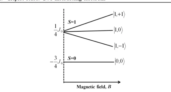
|J0|. The sign ofJ0determines whether the singlet or the triplet energy state lies lower. Figure 1.3 shows the energy levels of the singlet and triplet states for
J0 >0as a function of magnetic field.
In addition to electron-exchange, which splits the states into a singlet and triplets, there exists another important interaction, the anisotropic magnetic dipole-dipole in- teraction. This interaction lifts the three-fold degeneracy of the triplet state in zero magnetic field. The electron spin-spin dipolar interaction is given by the Hamiltonian
Hss=~2γe2
S1·S2
r3 −3(S1·r)( S2·r) r5
,
(1.9)
Because the two electrons are coupled, it is more convenient to express
Hssin terms
of the total spin operator
S, defined byS=S1+S2. Substituting this, together with
the angular momentum commutation relation and the identity
r2=x
2+y
2+z
2, Eqn. 1.9
can be written in the matrix form as:
1.2. Triplet state: Two interacting electrons 8
Figure 1.3: Exchange Interaction- The energy states of the two electron spin system exhibiting exchange interactionJ0 greater than zero.
Hss = ~2γe2
2 h
Sx Sy Sz
i
·
Dr2−3x2 r5
E D−3xy
r5
E −3xz
r5
D−3xy
r5
E D
r2−3y2 r5
E D
−3yz r5
E −3xz
r5
D−3yz
r5
E D
r2−3z2 r5
E
·
Sx Sy
Sz
(1.10)
The above euqation can be represented as
Hss =S·D·S, where Drepresent the spin-spin dipolar interaction tensor and the trace of the matrix is zero, i.e.,
tr(D)= 0.The angular brakets indicate that the elements of the parameter matrix
Dare averages over the electronic spatial wave function.
Dcan be diagonalized. Eqn.1.10 can be re-written in the principle-axis system (X, Y, and Z) of
Das:
Hss=DXSX2+DYSY2+DZSZ2,
(1.11) Here we introduce two parameters
Dand
E, whereD=3/2DZand
E= 1/2(D
X-D
Y) and are known as zero field parameter. Thus,
Hss=D(SZ2−1
2S2) +E(SX2+SY2),
(1.12) In the present of the external magnetic field the total Hamiltonian of the triplet is given as
He=γe~B ·S+D(SZ2−1
2S2) +E(SX2+SY2),
(1.13)
1.2. Triplet state: Two interacting electrons 9 The eigenfunction of
Heis linear combination of the kets
|+1i,|0iand
|−1i. In thelimit
B →0with
Bparallel to the principle axis Z, the zero field triplet eigenfunctions are:
|TXi = 1
√
2(|−1i − |+1i),
|TYi = i
√
2(|−1i+|+1i),
|TZi = |0i,
(1.14)
1.2.1 Photoexcited Triplets
Upon photoexcitation, the ground singlet state of the two interacting electrons can be easily excited to triplet state. The formation of triplets are due to intersystem crossing from the the excited singlet via spin-orbit coupling [21]. The photoexcited triplets are metastable state and would eventually decay to the singlet ground state of the system. However, the transition from the triplet to the ground singlet state is generally forbidden, which gives triplet state a certain lifetime before it decays. The probability
kmof transition “to and from" triplet
Tm(m
s= 0,±1) is proportional to the square ofthe matrix element of the spin-orbit coupling operator
HSO:
km ∝ |hS|HSO|TMi|2
(1.15) The spin orbit coupling is defined as
HSO =λL·S
(1.16)
where
λis the scalar constant. The direct calculation of the matrix element of this operator yields
hS0|HSO|T±i = √λ~
2(hψ1|lx|ψ2i+ihψ1|ly|ψ2i), hS0|HSO|T0i = −λ~
√
2hψ1|lz|ψ2i,
(1.17)
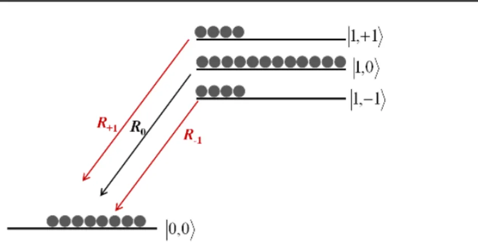
Equation 1.17 shows that the triplet sublevels have different transition probability.
These spin selective transition would lead to the non-equilibrium population of magnetic
sublevels of triplet states (see Figure 1.4). Such non-equilibrium electron polarization
[22, 23] can be utilized to polarize nuclear spin system in the host, which otherwise has
very weak polarization at experimentally accessible conditions .
1.2. Triplet state: Two interacting electrons 10
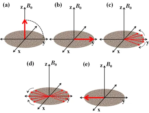
Figure 1.4: Non-equilibrium polarization- Schematic showing the singlet and triplet energy levels in the presence of external magnetic field B parallel to Z-axis of the triplet paramagnetic center. Selective transition to the ground singlet state under spin-orbit coupling builds high electron spin polarization in the triplet spin system.
1.2.2 Unique properties of photoexcited triplets
The ground singlet state of two interacting electron spins can be photoexcited to the triplet state. The spin orbit coupling which induces intersystem crossing to preferen- tially populate particular triplet sublevel and/or different decay rate from the triplet sublevels to the ground singlet state builds high spin polarization within the triplet spin system [21, 22]. Moreover, the dipolar interaction between the electron spins in the triplet state give rise to strong zero-field splitting [25]. These unique properties ex- hibited by photoexcited triplets has been exploited for the development of new magnetic resonance techniques such as single molecule optically detected magnetic resonance [24]
and zero field EPR [25]. Using continuous microwave illumination (under processes termed dynamic nuclear polarization) [26, 27], or using microwave pulses [28], highly polarized electron spin triplets can be used to polarize surrounding nuclear spins which otherwise owing to its small magnetic moment has very weak thermal polarization at ex- perimentally accessible conditions. Triplet states can also be used to mediate entangle- ment between mutually-coupled nuclear spins [29], on timescales much faster than their intrinsic dipolar coupling [30], thus suggesting the usefulness of photoexcited triplets as an optically driven mediator spins to couple nuclear spins in the lattice for quantum computing application [31]. These properties associated with the photoexcited triplets motivated us to study them in silicon and explore the microscopic processes exhibited by these spin system using magnetic resonance technique.
In this chapter, we will discuss about the triplet spin system in general and then
1.2. Triplet state: Two interacting electrons 11
give a brief introduction of the photoexcited triplet spin system in silicon relevant for
this thesis.
1.3. Photoextied triplets in silicon: SL1 centers 12
1.3 Photoextied triplets in silicon: SL1 centers
Oxygen and carbon are two major electrically inactive impurities always present in the silicon crystal, where oxygen takes the interstitial position while carbon is present at the sustitutional position. A lot of electrically active defect involving these two impurities are known to be formed as a result of radiation damage [32, 33]. The vacancy-oxygen complex (or A-centre) is the most prominent defect in either irradiated or implanted Si material. Its microscopic structure has been established by EPR and its vibrational properties by IR-absorption spectroscopy [33, 34, 35, 36]. This consists of an oxygen atom bridging a pair of Si neighbours of the vacancy. This defect is only stable when neutral and singly negatively charged. A deep single acceptor level or electron-trap at 0.17 eV below the conduction band minimum (E
c- 0.17 eV) [34] is associated with the negetive charged state of oxygen-vacancy complex (A-center).
In this thesis we focus on the photoexcited triplet states of these oxygen-vacancy complex in silicon, also known as SL1 center. It was first observed by Brower in 1972 using EPR spectroscopy [37] . SL1 center has orthorhombic symmetry of g and D- tensors with the principal values g
1= 2.0057, g
2= 2.0075, g
3= 2.0102 and D
1= -657 MHz, D
2= 350 MHz, D
3= 307 MHz corresponding to the principal axes
1, 2and
3parallel to
[110],[100], and [1¯10] crystal axes, respectively (see Figure 1.5).In silicon lattice the SL1 centers have six equivalent orientations along six different
h110icrystal axes shown in Figure 1.5 by dashed lines. When the magnetic field B
0is rotated in
(1¯10)plane varying the angle
θfrom 0
◦to 90
◦with respect to [110], the angle between B
0and principal axis
1for one of six groups of SL1 centers oriented along line [ad] is also varied from 0
◦(B||[110]) to 90
◦(B||[001]). For second group with the principal axis
3parallel to line [eh], the angle between B
0and these centers is always equal to 90
◦. Remaining four groups of SL1 centers make the intermediate angle with respect to direction of magnetic field. Two groups of these centers oriented along [bh] and [be] are magneto-equivalent (with the same angle between B
0and [bh] or [be]
directions) as well as the groups oriented along [ag] and [af]. In the conclusion, it needs to consider only four orientations of SL1 centers in silicon lattice along [ad], [eh], [bh], and [ag] directions.
EPR and spin dependent recombination studies on these centers has revealed that
the formation of triplets takes place due to simultaneous capture of photoexcited elec-
tron and hole by the ground singlet state of O-V complex [38]. Figure 1.6 shows the
schematic for the formation of triplets , SL1 center under bandgap illumination. The
1.3. Photoextied triplets in silicon: SL1 centers 13
Figure 1.5: Orientation of SL1 centers- Pictorial representation of the SL1 structure in silicon lattice. It also shows the principle axis system of the defect.
non-equilibrium spin polarization in these triplets was confirmed by the observation of absorption and emission EPR signal simultaneously [37].
Figure 1.6: Formation of SL1 center under photoexcitation- The shcematic show- ing the photoexcitation of singlet ground state of oxygen-vacancy complex to the triplet state on simultaneous capturing of photoexcited carriers. The triplet population are equally filled initially but the selective transition to the ground singlet state builds the spin polar- ization in the sublevels.
1.3. Photoextied triplets in silicon: SL1 centers 14 The non-equilibrium polarization of SL1 center has been previously used to hyper- polarize the
29Si nuclear spins using optical and dynamic nuclear polarization technique [39, 40]. Such hyperpolarized nuclear spin system in silicon would be a step towards the realization of recent proposal of
29Si nuclear spin based quantum computer [8, 9]. The experimental demonstration of long coherence time for
29Si nuclear spin in silicon makes it really an exciting system for quantum computing [16]. However, till date the quantum computing scheme using host stable isotope in solid has been demonstrated only with
13
C nuclear spins in diamond via coherent coupling to the spin-triplet nitrogen-vacancy centers [41, 42, 43].
Here we explore the electronic properties of SL1 center using electrical and con- ventional magnetic resonance technique and demonstrate that the interaction of these triplet centers with other electron and nuclear spin in the lattice leads to some exciting and interesting physics. We have demonstrated a well designed set of experiments to provide new information on spin-spin interactions between defect centers that can lead to the change in conductivity of the sample.
Moreover,using pulsed EPR spectrometer we were able to study the dynamical prop-
erties of these photoexcited triplets as well as the interaction between the electron spin
and
29Si nuclear spin in the lattice. Finally we have demonstrated the coherent manip-
ulation of
29Si nuclear spin state via photoexcited triplet electron spin and show the
coherent transfer of quantum information back and forth between the strongly hyperfine
coupled triplet electrons and the nearest neighbor
29Si nuclear spin, thus leading to the
successful demonstration of
29Si quantum memory in silicon.
1.4. Organization of thesis 15
1.4 Organization of thesis
Chapter 1 provides the motivation for the research presented in this thesis. This is followed with a general description of photoexcited triplet spin system. In addition, we introduce the triplet spin system in silicon relevant in this thesis.
Chapter 2 introduces the basics of magnetic resonance. In this chapter we discuss the fundamentals of pulsed EPR and EDMR techniques used in this thesis.
Chapter 3, 4 and 5 focuses on the main results of this thesis.
Chapter 3 discusses the electrical detection of spin dependent recombination process in phosphorus doped
γ-irradiated silicon. First section of this chapter shows that with the introduction of these irradiation defects we can probe the spin state of phosphorus atoms in the bulk using EDMR spectroscopy, in contrast to the previous studies where paramagnetic centers situated near to the silicon surface can be probed using EDMR.
Further we reveal that the dipolar interaction between triplets and phosphorus electron spin lead to the demonstration of electrical detection of cross relaxation signal in silicon.
This new and sensitive method can also be used to probe paramagnetic centers in the lattice.
Chapter 4 is devoted to the pulsed EPR study of SL1 center in silicon. Here we have characterized the lifetime of the triplets as well as its interaction with the nearest neighbor
29Si present in the lattice. It was found that all the triplet sublevels of SL1 centers were equally populated after the initial laser pulse. However, the different decay rates from the sublevels to the ground singlet state via spin-orbit coupling builds high spin polarization in these spin system. We use the electron spin echo envelope modulation spectroscopy to determine the hyperfine interaction with those
29Si nuclear spin which are unresolved in the EPR spectrum.
In Chapter 5 we used the strong coupling of the SL1 center with the nearest neighbor
29
Si nuclear spins to demonstrate the Rabi oscillation of nuclear spins as well as the coherent transfer of quantum information between the electron and nuclear spin.
Chapter 6 summarizes the results obtained in this work.
Bibliography
[1] R. Feynman, Quantum mechanical computers. Opt. News 11, 11-46 (1985).
(Cited on page 1.)
[2] P. W. Shor, J. Sci. Stat. Comput, 26, 1484 (1997). (Cited on page 1.) [3] P. Domokos, J. M. Raimond, M. Brune, and S. Haroche , Phys. Rev. A,
52, 3554 (1995). (Cited on page 1.)
[4] J. I. Cirac and P. Zoller, Phys. Rev. Lett., 74, 4091 (1995). (Cited on page 1.)
[5] N. A. Gershenfeld and I. L. Chuang, Science, 275, 350 (1997). (Cited on page 1.)
[6] N. H. Bonadeo,J. Erland, D. Gammon, D. Park, D. S. Katzer and D. G.
Steel, Science, 282, 1473 (1998). (Cited on page 2.)
[7] B. E. Kane, Nature, 393, 133 (1998). (Cited on pages 2 and 3.)
[8] T. D. Ladd, J. R. Goldman, F. Yamaguchi, Y. Yamamoto, E. Abe, and K.
M. Itoh, Phys. Rev. Lett. 89, 017901 (2002). (Cited on pages 2 and 14.) [9] K. M. Itoh, Solid State Commun. 133, 747 (2005). (Cited on pages 2
and 14.)
[10] G. Feher, Phys. Rev. 114, 1219 (1959). (Cited on page 3.)
[11] J. J. L. Morton, A. M. Tyryshkin, R. M. Brown, S. Shankar, B. W. Lovett, A. Ardavan, T. Schenkel, E. E. Haller, J. W. Ager and S. A. Lyon, Nature, 455, 1085 (2008). (Cited on page 4.)
[12] A.M. Tyryshkin, S. A. Lyon, A. V. Astashkin, and A. M. Raitsimring, Phys.
Rev. B 68, 193207 (2003). (Cited on page 4.)
[13] S. Simmons, R. M. Brown, H. Riemann, N. V. Abrosimov, P. Becker, H. J.
Pohl, M. L. W. Thewalt, K. M. Itoh and J. J. L. Morton, Nature 470 69 (2011). (Cited on page 4.)
[14] E. Hahn, Phys. Rev. B. 80, 460 (1946). (Cited on page 5.)
Bibliography 17 [15] A. E. Dementyev, D. Li, K. MacLean, and S. E. Barrett, Phys. Rev. B 68,
153302 (2003). (Cited on page 5.)
[16] T. D. Ladd, D. Maryenko, Y. Yamamoto, E. Abe, and K. M. Itoh, Phys.
Rev. B 71, 014401 (2005). (Cited on pages 5 and 14.)
[17] G. Lampel, Phys. Rev. Lett., 20, 491 (1968). (Cited on page 5.)
[18] A. S. Verhulst, I. G. Rau, Y. Yamamoto and K. M. Itoh, Phys. Rev. B, 71, 235206 (2005). (Cited on page 5.)
[19] H. Hayashi, T. Itahashi, K. M. Itoh, L. S. Vlasenko, and M. P. Vlasenko, Phys. Rev. B 80, 045201 (2009). (Cited on page 5.)
[20] A. E. Dementyev, D. G. Cory and C. Ramanathan, J. Chem. Phys. 134, 154511 (2011). (Cited on page 5.)
[21] J.H.van der Waals, Appl. Magn. Reson. 20, 545 (2001). (Cited on pages 9 and 10.)
[22] M. Deimling, H. Brunner, K. P. Dinse, K. H. Hausser, and J. P. Colpa, J.
Magn. Reson. 39, 185 (1980). (Cited on pages 9 and 10.)
[23] S. P. McGlynn, T. Azumi, M. Kinosita, Molecular spectroscopy of the triplet state, Prentice-Hall, Englewood Cliffs, NJ (1969). (Cited on page 9.) [24] J. Wrachtrup, C. von Borczyskowski, J. Bernard, M. Orritt and R. Brown,
Nature 363, 244 (1993). (Cited on page 10.)
[25] T. Chin Yang, D. J. Sloop, S. I. Weissman and T. Sung Lin , J. Chem.
Phys. 113, 11194 (2000). (Cited on page 10.)
[26] P. Bachert, H. Brunner, K. H. Hausser, and J. P. Colpa, Chem. Phys. 91, 435 (1984). (Cited on page 10.)
[27] K. Takeda, K. Takegoshi and T. Terao, J. Phys. Soc. Japan 73, 2319 (2004).
(Cited on page 10.)
[28] J. Schmidt, D. J. van den Heuvel, A. Henstra, T.-S. Lin and W. Wencke-
bach, Pure & App. Chem. 64, 859 (1992). (Cited on page 10.)
Bibliography 18 [29] M. Schaffry, V.Filidou, S. D. Karlen, E. M. Gauger, S. C. Benjamin, H.
L. Anderson, A. Ardavan, G. A. D. Briggs, K. Maeda, K. B. Henbest, F.
Giustino, J. J. L. Morton and B. W. Lovett, Phys. Rev. Lett. 104, 200501 (2010). (Cited on page 10.)
[30] V.Filidou, S. Simmons, S. D. Karlen, H. L. Anderson, F. Giustino, J. J. L.
Morton
in preparation(2011). (Cited on page 10.)
[31] A. M. Stoneham, A.J. Fischer and P. T. Greenland, J. Phys. Cond. Mat.
15, L447 (2003). (Cited on page 10.)
[32] A. V. Yukhnevich, Sov. Phys.-Solid State, 7, 259 (1965). (Cited on page 12.) [33] G. D. Watkins, J. W. Corbett and R. M. Walker, J. Appl. Phys 30, 1198
(1959). (Cited on page 12.)
[34] G. D. Watkins and J. W. Corbett, Phys. Rev. 121, 1001 (1961). (Cited on page 12.)
[35] J. W. Corbett, G. D. Watkins, R. M. Chrenko and R. S. McDonald, Phys.
Rev. 121, 1015 (1961). (Cited on page 12.)
[36] F.A. Abou-el-Fotouh and R.C. Newman, Sol. State Commun. 15, 1409 (1974). (Cited on page 12.)
[37] K. L. Brower, Phys. Rev. B 4, 1968 (1971). (Cited on pages 12 and 13.) [38] L. S. Vlasenko, Yu. V. Martynov, T. Gregorkiewicz, and C. A. J. Ammer-
laan, Phys. Rev. B 52, 1144 (1995). (Cited on page 12.)
[39] L. S. Vlasenko, M. P. Vlasenko, D. S. Poloskin, R. Laiho, H. Hayashi, T.
Itahashi, A. Sagara, and K. M. Itoh, Phys. Stat. Sol. (c). 3, 12 (2006).
(Cited on page 14.)
[40] T. Itahashi, H. Hayashi, K.M. Itoh, D.S. Poloskin, and L.S. Vlasenko, Phys- ica B 404, 5054 (2009). (Cited on page 14.)
[41] F. Jelezko, T. Gaebel, I. Popa, M. Domhan, A. Gruber, and J.Wrachtrup, Phys. Rev. Lett. 93, 130501 2004 (Cited on page 14.)
[42] M. V. Gurudev Dutt, L. Childress, L. Jiang, E. Togan, J. Maze, F. Jelezko, A. S. Zibrov, P. R. Hemmer, and M. D. Lukin, Science 316, 1312 (2007).
(Cited on page 14.)
Bibliography 19 [43] P. Neumann, N. Mizuochi, F. Rempp, P. Hemmer, H. Watanabe, S. Ya-
masaki, V. Jacques, T. Gaebel, F. Jelezko, and J. Wrachtrup, Science 320,
1326 2008 (Cited on page 14.)
Chapter 2
Magnetic Resonance
Ever since the first experimental observation of an electron paramagnetic resonance
(EPR) signal by E. K. Zavoisky at Kazan State University, Russia, the EPR spec-
troscopy has made a great contribution for determining the structure and dynamics
and the spatial distribution of paramagnetic species in host materials. The develop-
ment of pulsed EPR (pEPR) and electrical detection of magnetic resonance (EDMR)
spectroscopy had further enriched the field of magnetic resonance and its contribution
towards understanding atomic physics. In this chapter we discuss the basic understand-
ing of the underlying theory and fundamentals of these magnetic resonance techniques
utilized in this thesis.
2.1. Introduction 21
2.1 Introduction
2.1.1 Electron magnetic moment and its interaction with magnetic field
From classical electrodynamics, a rotating electrically charged body creates a magnetic dipole with magnetic poles of equal magnitude but opposite polarity. If the electron is visualized as a classical charged particle literally rotating about an axis with angular momentum
J, its magnetic dipole moment
µis given by:
µ=γJ,
(2.1)
where
γis the gyromagnetic ratio. Thus, an electron can be considered as a tiny bar magnet and an application of static magnetic field B will exert a torque equal to the time derivative of the angular momentum:
dJ
dt =µ×B,
(2.2)
Using Eqn. 2.1 , we re-write Eqn. 2.2 as:
dµ
dt =µ×γB,
(2.3)
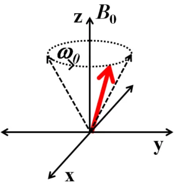
The above equation illustrates that the magnetic moment precess about the magnetic field as shown in Figure 2.1. If the applied static magnetic field is along the z-axis, i.e.
B =
B0zˆ, the magnetic moment
µrotates at an angular frequency
ω0=
|γ |B0[1].
The angular frequency is also known as Larmour frequency.
The magnetic moment also takes on a potential energy
Uin the presence of magnetic field
Bwhich is given as,
U=−µ.B
(2.4)
Quantum mechanics predicts that the angular momentum J can take only some dis- crete sets of value. i.e. quantization of angular momentum. We introduce an quantum operator I, such that J=
~I. I
2has eigenvalues
I(I + 1), where Iis either integer or half integer. Any component of I (for example I
z) commutes with I
2, so we can specify simultaneous eigenvalues of both I
2and I
z. Let
mbe the eigenvalue of I
zwhich may take any of the 2I+1 values
I,I -1,· · ·· -I. Considering this fact, the Hamiltonian of the electron in the presence of the magnetic field is given by equation
H=−µ.B,
(2.5)
2.1. Introduction 22
Figure 2.1: Larmor Frequency - Schematic showing the precession of the magnetic moment in the presence of externally applied magnetic field.
With magnetic field taken along
zˆ-direction ,
H=−γ~B0Iz,
(2.6)
The eigenvalue of this Hamiltonian is simple,
E=-γ~B
0m, where m=I, I −1,· ···,−I. For spin-1/2 particle (I=1/2), the angular momentum along the z-axis has twoˆ
eigenstates,
|αiand
|βi.These states are defined as
|αi=
|1/2,+1/2iand
|βi=
|1/2,−1/2i
using the notation
|I, mi. The states |αiand
|βiare called the Zeeman eigenstates of the single spin-1/2 and obey the following eigenequation:
Iz|αi= +1/2|αi,Iz|βi=−1/2|βi
(2.7)
Using Eqn. 2.6 and 2.7, the eigen energy of the state
|αiand
|βiis computed to be
-
~ω0/2 and
~ω0/2, respectively. The state
|αihas lower energy, meaning it is parallel to
the magnetic field while the state
|βiis antiparallel to the magnetic field. The energy
difference between the states is
~ω0and thus any transition between these states must
involve energy quanta
~ω0. The required energy corresponds exactly to the Larmor
frequency, giving rise to the concept of “resonance".
2.1. Introduction 23 2.1.1.1 Effect of alternating magnetic field
In this section we will consider the effect of alternating magnetic field (microwave field) on the magnetic moment. Let’s consider the situation in which, in addition to the static magnetic field
B0along
z-axis, an external perpendicular alternating magneticˆfield
Bxcos (Ωt)ˆxis applied. This linearly polarized microwave field can be decomposed into right and left circularly polarized microwave fields in the
xy-plane. In the rotatingwave approximation, only the right-circularly polarized field (B
1(t)=
B1(ˆxcos(Ωt) + ˆysin(Ωt))) effects the magnetic moment near the resonance condition Ω'ω0
and the effect of the left-circularly polarized field may be neglected because it is far off-resonance.
The equation of motion of the magnetic moment can now be written as
dµdt =µ×γ(B1(ˆxcos(Ωt) + ˆysin(Ωt)) +B0z),ˆ
(2.8) The time dependence of
B1field adds to the complexity of solving the above equation of motion. However, the time dependence can be removed if we consider a coordinate system rotating at an angular frequency
Ω. From this rotating frame,B1is stationary and thus Eqn. 2.8 can be re-written as
dµ
dt =µ×γ(B1xˆ0+ (B0−Ω/γ) ˆz0),
(2.9) Therefore the magnetic moment is subjected to a precession about the effective magnetic field,
Bef f=B
1xˆ0+B
0−Ω/γzˆ0. Thus, beside the stationary
B1,the magnetic field along the z
0-axis that coincides with the z-axis of the laboratory frame is reduced from
B0to
B0−Ω/γ. If the resonance condition is fulfilled exactly (Ω=γB0), the effective field is then simply
xˆ0B1. The magnetic moment will then precess in the y-z plane remaining parallel to
B1. The rotation frequency
ω1=γB
1, is called the Rabi oscillation.
By turning the alternating field on and off at proper timings, we are able to control the precession angle (θ) of the magnetic moment, i.e.,
θ=γB1tw, where
twis the duration of the alternating field. If
twis chosen such that
θ=
π, the pulse would simply invertthe magnetic moment. Such a pulse in literature is defined as
π-pulse, similarly we candefine a
π/2-pulse.So far we only considered single spin interacting only with the magnetic field. How-
ever, in reality a sample contains large number of identical spins and is not isolated from
various interaction in the lattice. The macroscopic magnetization M is a vector sum
of all the individual magnetic moments in the sample, and for a large enough number
of spins the x-y component will cancel out and the resultant net magnetization will be
2.1. Introduction 24 along the +z axis and exactly parallel to the external field. Thus, in thermal equilib- rium, we write the equilibrium magnetization as
Meq=
(0,0, M0). Now, if the systemof spin is not in thermal equilibrium than under various interaction the magnetization reaches
Meq, which could be explained by the Bloch equation [2]:
dM
dt =M ×γ B+ 1
T1(Meq−Mk)− 1
T2 M⊥,
(2.10)
where
Mkand
M⊥are the longitudinal and transverse component of magnetization
Mand
T1,
T2are the relaxation processes. Once disturbed from its equilibrium,
the magnetization will interact with its surroundings and return to equilibrium. This
process is called relaxation, and is characterized by two time constants,
T1and
T2. The
spin-lattice relaxation time,
T1, describes how quickly the magnetization recovers its
longitudinal component along the z axis, in other words, it is the amount of time in
which the energy absorbed from the pulse is dissipated to the lattice as the system
returns to equilibrium. The transverse relaxation time,
T2, describes how quickly the
net magnetization dissipates in the x-y plane, i.e. how quickly the spins lose coherence
and fan out 360 degrees into randomized precession.
2.2. Pulsed Electron Paramagnetic Resonance 25
2.2 Pulsed Electron Paramagnetic Resonance
The heart of pulse EPR experiments lies in the manipulation of the magnetization by short and intense microwave pulses that have specific tip angles, and then the subsequent detection of the magnetic behavior during its return to equilibrium. Pulses are often named by their tip angles, and the most commonly employed tip angles are
π/2 (90degrees) and
π(180 degrees). A
π/2 pulse will tip the magnetization into the x-y plane,and is also called a saturating pulse because the magnetization along the z axis goes to zero, i.e. the population difference between parallel and antiparallel states goes to zero.
A
πpulse is also called an inversion pulse, because it tips the magnetization 180 degrees.
Using well defined pulse sequences we can measure the various relaxation process like
T1and
T2time.
The simplest way to measure the
T2, would be to apply a
π/2 pulse which will tip themagnetization in the x-y plane and then monitor the decay of magnetization with time.
However, in reality the spin ensemble do not have the same Larmor frequency due to the inhomogeniety in the magnetic field and thus the transverse magnetization tends to fan out in the x-y plane at time scale faster than
T2. The magnetic field inhomogeneity (δB
z) arises as external magnetic field (B
0) is not homogeneous over sample volume and also because of the presence of other paramagnetic centers which creates local magnetic field. As a result of this, the Larmor frequency of the spins is shifted by
δω=|γδBz |.A spin packet in a pEPR represents a group of spins having same Larmor frequency.
As seen from the frame rotating at an angular frequency
ω0, the spin packet precess at at angular frequency
δω. The magnetization vector is composed of many spin packetswhich are precessing with different angular frequency and the magnetization vector vanishes as it fan out over the entire x-y plane. This is called a Free Induction Decay (FID). Thus to measure the
T2time we need to overcome the effect of inhomogeneity.
This can be achieved by using a Hahn echo pulse sequence [3] . 2.2.1 Hahn echo method
The basic idea of the Hahn echo method is to overcome the unwanted decay of the
transverse magnetization due to the magnetic field inhomogeneity. The pulse sequence
employed is
π/2−τ−π−τ−echo. The firstπ/2 pulse will bring the magnetization inthe x-y plane where the magnetization evolves over the time
τ. As mentioned above, if
we look down the z axis at the x-y plane, there will be faster moving spin packets and
slower moving spin packets, depending on their relative frequencies. When we apply a
2.2. Pulsed Electron Paramagnetic Resonance 26
πpulse, the magnetization is inverted 180 degrees yet still rotates in the same direction with the same speed. Now, instead of moving away from the slower spin packets, the faster moving spin packets move towards the slower spin packets. The magnetization eventually refocuses at time
τafter the
πpulse to form an echo. The echo intensity as a function of waiting time
τwill eventually gives us the
T2time of the spin system under observation. Figure 2.2 is the pictorial representation of the Hahn echo method describing the effect of pulse sequences on the spins.
Figure 2.2: Hahn Echo - Schematic showing the spin behavior under the application of Hahn echo pulse sequence. (a) Initialization of spin along the applied magnetic field, which under the application ofπ/2 pulse goes to the x-y plane(b). (c) Dephasing of spins in the x-y plane which is refocused using theπpulse (d). (e) The occurence of echo as the spins get refocused.
2.2.2 Spin-Spin Interaction
The other advantage of pEPR is to study the interaction of paramagnetic centers with
nuclear spins in the lattice. The paramagnetic centers in solid generally interacts with
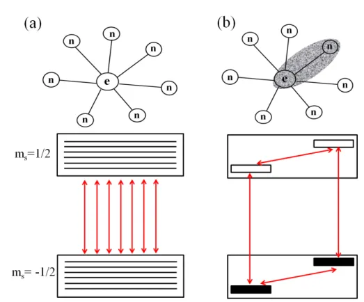
more than one nuclear spin which inhomogeneously broadens the EPR spectrum (Figure
2.3 (a)). Because of this poor resolution in cw-EPR, many magnetic parameters
essential for the characterization of the paramagnetic centers can not be addressed. A
2.2. Pulsed Electron Paramagnetic Resonance 27
Figure 2.3: Coupled electron-nuclear spin system - (a) Multi-spin system: the elctron spin interacting with many nuclear spins to give an EPR spectrum consisting of a large number of transition. (b) Two-spin subsystem: only the interaction of the electron spin with one nuclear spin,I= 1/2, is considered. The EPR spectrum of such a subsystem consists of two (allowed) transitions.
way out for this is to use pulse EPR method, which can be use to address subsystem of a multi-spin system. Figure 2.3(b) shows the spin system consisting of one electron and one nuclear spin. The rotating-frame spin Hamiltonian of such a two-spin subsystem is given by
H0= ΩsSz+ωIIz+I
AS, (2.11) where
Ωs=
ωs-
ωmw,
Ais the hyperfine coupling tensor,
ωs=γ
eB
0and
ωI=γ
IB
0. The two allowed (∆m
s=±1,
∆mI=0) and two forbidden (∆m
s=±1,
∆mI=±1) electron spin transition frequencies in the rotating frame can be expressed as
ω13= Ωs+1
2(ω12−ω34),
(2.12)
ω24= Ωs−1
2(ω12−ω34),
(2.13)
2.2. Pulsed Electron Paramagnetic Resonance 28
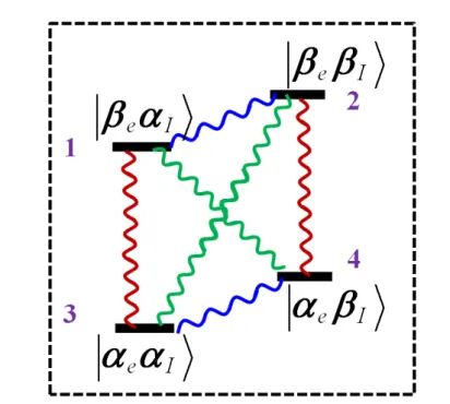
Figure 2.4: Coherences in four level system - Schematic showing the four level system consisting of hyperfine coupled electron spin S = 1/2 and nuclear spin I = 1/2.
The zig-zag lines represent the various possible coherences that can be generated under the application of resonant microwave and radio frequency pulse.
and
ω14= Ωs+1
2(ω12+ω34),
(2.14)
ω23= Ωs−1
2(ω12+ω34),
(2.15)
with the two nuclear transition frequencies, also know as “electron nuclear double reso- nance(ENDOR)" frequencies given as
ωα= Ω12= [(msA+ωI)2+ (msB)2]1/2,

![Figure 2.6: Low field EDMR setup - Cryostat and the electrical circuit used to realize low field EDMR setup used in this work [10].](https://thumb-ap.123doks.com/thumbv2/123deta/6071540.2079790/38.892.224.735.438.781/figure-field-edmr-setup-cryostat-electrical-circuit-realize.webp)
