842 IEICE TRANS. FUNDAMENTALS, VOL.E102–A, NO.6 JUNE 2019
LETTER
A Reduction of the Number of Components Included in Direct Simulation Type Active Complex Filter
Tatsuya FUJII†,Nonmember andKazuhiro SHOUNO†a),Member
SUMMARY In this paper, a reduction of the number of components included in direct simulation type active complex filter is proposed. The proposed method is achieved by sharing NIC’s (Negative Impedance Con- verters) which satisfy some conditions. Compared with the conventional method, the proposed one has wide generality. As an example, a third-order complex elliptic filter is designed. The validity of the proposed method is confirmed through experiment.
key words: complex, active, filter, NIC
1. Introduction
In recent years, many techniques concerned with the complex signal processing have been presented, not only in the field of digital circuits but also in the field of analog circuits. The complex filters are important for the Low-IF radio systems [1],[2], SSB (Single Side Band) communication systems[3]
and so on.
It is known that the direct simulation method[4]–[6]
offers the advantage of a simple design. The authors have proposed a complex filter using NIV’s (Negative Immittance Inverters)[4]. Compared with the conventional circuits[5], the complex filter using NIV’s can be realized with fewer active components. However, it is difficult to apply this technique[4]to the complex filters with finite transmission zeros.
In this paper, a reduction of the number of components included in direct simulation type active complex filter is proposed. The proposed method is achieved by sharing NIC’s (Negative Impedance Converters). As an example, a third-order complex elliptic filter is designed. The validity of the proposed method is confirmed through experiment. The number of the required components of the proposed circuit is compared with that of the conventional one.
2. Proposed Method
In many cases, complex prototype filters include not only resistors and capacitors but also imaginary resistors and in- ductors. The imaginary resistors and inductors can be real- ized by using gyrators. Therefore, the complex filters can be realized by using resistors, capacitors and gyrators. When
Manuscript received December 27, 2018.
Manuscript revised February 22, 2019.
†The authors are with Graduate School of Systems and Infor- mation Engineering, University of Tsukuba, Tsukuba-shi, 305-8573 Japan.
a) E-mail: [email protected] DOI: 10.1587/transfun.E102.A.842
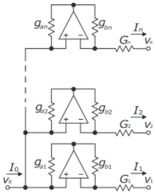
Fig. 1 Several NIC’s connected to the same node.
Fig. 2 An NIC and resistors.
the complex filter is realized directly by using operational amplifiers, gyrators are realized by using NIC’s[5]. Except for special case[7], complex filters composed of resistors, capacitors, and gyrators are realized as circuits including two or more NIC’s connected to the same nodes.
In this section, a method for sharing NIC’s is proposed.
First, when(I0,I1,· · ·In)t=Ya(V0,V1,· · ·,Vn)t, aY-matrix of the circuit shown in Fig. 1 has the following form.
Ya=
* . . . . . . . . . ,
Ya0 (ga1G1)/gb1 (ga2G2)/gb2 · · · (ganGn)/gbn
−G1 G1 0 · · · 0
−G2 0 G2 · · · ...
... ... . .. . .. 0
−Gn 0 · · · 0 Gn
+ / / / / / / / / / - ,
(1) where Ya0 = −{(ga1G1)/gb1 + (ga2G2)/gb2 + · · · + (ganGn)/gbn}.
Secondly, the Y-matrix of the circuit shown in Fig. 2 becomes as follows. When (I0,I1,· · ·,In)t = Yb(V0,V1,· · ·,Vn)t.
Copyright © 2019 The Institute of Electronics, Information and Communication Engineers
LETTER
843
Fig. 3 Conventional circuit (n=3)[4],[5].
Fig. 4 Proposed circuit (n=3).
Yb=
* . . . . . . . . . ,
Yb0 (gcG1)/gd (gcG2)/gd · · · (gcGn)/gd
−G1 G1 0 · · · 0
−G2 0 G2 · · · ...
... ... . .. . .. 0
−Gn 0 · · · 0 Gn
+ / / / / / / / / / - ,
(2) whereYb0=−(gc/gd)(G1+G2+· · ·+Gn). By comparing Eq. (1) and Eq. (2), it can be seen that the circuits shown in Figs. 1 and 2 are equivalent to each other if the following equation is satisfied.
ga1/gb1=ga2/gb2=· · ·=gan/gbn=gc/gd (3) Replacing the circuit of Fig. 1 with that of Fig. 2 reduces (n-1) operational amplifiers and 2(n-1) resistors.
3. Design Example
A complex filter which satisfies the following specifications
is designed.
Third-order complex elliptic filter
Passband 4.5–5.5 kHz
Passband ripple 1.25 dB Minimum attenuation 40.5 dB
In the same fashion as the existing researches [4], [5], a circuit shown in Fig. 3 which meets the above specifications can be designed. In this figure, circuits A surrounded by dotted lines are removed[5]. WhenRL =1, circuits B sur- rounded by dotted lines are also removed. Bringing OA’s represented by A, B, C, D, E, and F together gives the cir- cuit shown in Fig. 4. The operational amplifiers used in this experiment are LF356’s. The feedback resistors of the NIC’s are decided such that the influence of GB product of operational amplifiers decrease.
The experimental results obtained by the measurement technique described in[8]and simulated results are shown in Figs. 5 and 6. In these figures, dash dotted lines show the gain characteristics of the proposed circuit realized by using
844 IEICE TRANS. FUNDAMENTALS, VOL.E102–A, NO.6 JUNE 2019
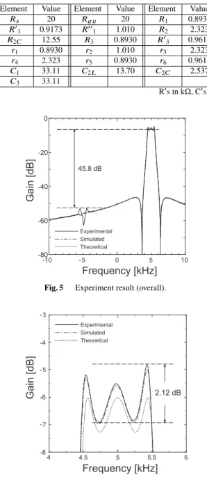
Table 1 Element values of the experimental circuit shown in Fig. 4.
Element Value Element Value Element Value
Rs 20 Rg y 20 R1 0.8930
R01 0.9173 R001 1.010 R2 2.323
R2C 12.55 R3 0.8930 R03 0.9614
r1 0.8930 r2 1.010 r3 2.323
r4 2.323 r5 0.8930 r6 0.9614
C1 33.11 C2L 13.70 C2C 2.537
C3 33.11
R0s in kΩ, C0s in nF
Fig. 5 Experiment result (overall).
Fig. 6 Experiment result (near passband).
ideal operational amplifiers with GB products of 5 MHz. The experimental results show that the proposed filter exhibits a complex elliptic response and an image rejection of 45.8 dB.
The number of the required components are summa- rized in Table 2 and Table 3. From Table 2, it is found that the components required in the proposed circuit are fewer than those in the conventional complex filter with finite trans- mission zeros. From Table 3, it is found that the required components are not reduced when the proposed method is applied to the complex filter without finite transmission ze- ros[4]. Although it is difficult that the conventional method [4]is applied to the complex filter with finite transmission
Table 2 The number of the required components for complex filter with finite transmission zeros.
Proposed Conventional[5],[6]
Order OA C R OA C R
3rd 6 8 29 14 8 49
5th 10 14 49 26 14 87
(2k+1)th 4k+2 6k+2 20k+9 12k+2 6k+2 38k+11 OA: Operational Amplifier
Table 3 The number of the required components for complex filter with- out finite transmission zeros.
Proposed Conventional[4]
Order OA C R OA C R
3rd 6 6 27 6 6 27
5th 10 10 44 10 10 44
(2k+1)th 4k+2 4k+2 17k+10 4k+2 4k+2 17k+10 OA: Operational Amplifier
zeros, the proposed one can applied to the filters with or without finite transmission zeros.
4. Conclusion
In this paper, a reduction of the number of components included in direct simulation type active complex filter is proposed. The validity of the proposed method is con- firmed through experiment. Compared with the conventional method, the proposed method has wide generality.
The further investigation is required to compensate GB product of the operational amplifiers.
References
[1] S. Tanaka: “Circuit techniques for mobile communication transceivers,” IEICE Trans. Electronics (Japanese Edition), vol.J89- C, no.10, pp.622–640, Oct. 2006.
[2] K.W. Martin, “Complex signal processing is not complex,” IEEE Trans. Circuits Syst. I, Reg. Papers, vol.51, no.9, pp.1823–1836, Sept.
2004.
[3] X. Zhang, M. Iwahashi, and N. Kambayashi, “A novel narrow-band bandpass filter and its application to SSB communication,” IEICE Trans. Electronics, vol.E80-C, no.7, pp.1010–1015, July 1997.
[4] T. Fujii and K. Shouno, “Synthesis of a complex coefficient filter using negative immittance inverters,” IEICE Trans. Fundamentals (Japanese Edition), vol.J100-A, no.6, pp.236–239, June 2017.
[5] C. Muto and N. Kambayashi, “A realization of imaginary resistances and its application to analog signal processing,” IEICE Technical Re- port, CAS92-75, Nov. 1992 (Japanese Edition).
[6] K. Shouno and Y. Ishibashi, “Synthesis and active realization of three- phase complex coefficient filter using gyrators,” IEEE Trans. Circuits and Systems, vol.55, no.7, pp.550–553, Aug. 2008.
[7] K. Shouno, S. Ono, and Y. Ishibashi, “Synthesis of a complex RiCR fil- ter using grounded imaginary resistors and its active simulation,” Proc.
24th International Technical Conf. on Circuits/Systems, Computers and Communications (ITC-CSCC2009), pp.649–652, July 2009.
[8] K. Shouno and Y. Ishibashi, “A Note on the measurement method of the frequency response of a complex coefficient filter,” IEICE Trans.
Fundamentals (Japanese Edition), J83-A, no.12, pp.1486–1494, Dec.
2000.
![Fig. 3 Conventional circuit ( n = 3) [4], [5].](https://thumb-ap.123doks.com/thumbv2/123deta/5634135.1501490/2.892.102.765.113.860/fig-conventional-circuit-n.webp)