Expediting Experiments across Testbeds with AnyBed: A Testbed-Independent Topology Configuration System and Its Tool Set
11
0
0
全文
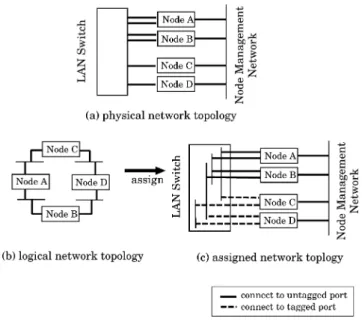
(2) IEICE TRANS. INF. & SYST., VOL.E92–D, NO.10 OCTOBER 2009. 1878. tools on major large scale NETs, and other network emulation environments. Section 4 and Sect. 5 show the design of AnyBed architecture and the details of implementation. We present the evaluation and the verification of the implementation in Sect. 6 and Sect. 7. Also, we discuss the limitation of AnyBed in Sect. 8. Finally, we conclude this paper in Sect. 9. 2.. Building Networks on NET. In this section, we describe design backgrounds of AnyBed. We first analyze general steps to perform experiment on a NET without assistant tools. Next, we focus on building an experimental network among all procedures. 2.1 Steps to Perform Experiments on NETs In this section, we analyze general steps to perform experiments in NETs. These steps are derived from experiences when our laboratory fellows performed experiments in NETs. The steps are described below. First, the user designs the logical network topology for his or her experiments. The user also gives roles for each node; some nodes are used to run programs, some nodes are used to collect the experimental results. Second, the user assigns physical resources to the designed network topology. For example, an experimental node is assigned to a physical or virtual node, or an experimental interface is mapped to a physical or virtual interface. The user assigns IP addresses to network interfaces of experimental nodes. The user assigns VLANs and network addresses to each subnet on the logical network topology. In these sequences, the user must assign appropriate resources along with the physical network topology of an NET, that is, the wiring, the number of physical network interfaces, the bandwidth of physical network interfaces and the performance of CPU. Third, the user builds the network by setting up physical nodes and layer 2 switches. The user configures network interfaces, routing and name resolution for each node. The user configures VLANs on layer 2 switches. In addition, the user injects programs used for the experiment to each node and setup these programs. Fourth, the user conducts the experiment. The user runs programs on each node in the specified sequence. Finally, the user collects results of the experiment and then restores nodes and switches. The results contain the output of programs and the state of each node. The results are saved into the hard disks of each node or transferred to remote node. There are various NETs in the world such as desk-side PCs, a PC cluster in your laboratory, and large scale centralized NETs. In various testbeds, the user selects a suitable testbed for the scale of his experiments. For example, during prototype implementation, it is enough to test it by his desk-side PCs. However, if he needs more complex emulated network like emulated AS-level topology, he cannot. Fig. 1. Topology assignment.. perform experiments by his desk-side PCs. He may move to a larger scale testbed. 2.2. Steps to Build Experimental Networks. In the steps described above, the part of building experimental network empirically spends long time on the overall experiment. Besides, as the number of nodes increases, the configuration workload increases as well. For example, when our fellows performed the experiment about IP Traceback [5] on StarBED, we consumed 4 days to build a logical network topology on 64 nodes and 2 switches of StarBED, where we have emulated the BGP topology of top 50 Autonomous Systems (AS) by considering a BGP node to an AS. In order to expedite experiments, we focus on reducing the overhead on the part of building experimental networks on an NET. We divided the part of building experimental networks on an NET into five steps as follows: 1. Design A user designs a logical network topology for an experiment (Fig. 1-(b)). The user considers about not only a layer 3 network topology but also layer 2 network topology. 2. Assignment The user assigns resources of an NET to each experimental node according to the designed logical network topology. The resources to be assigned are PCs, Ethernet Links, VLANs, IP addresses (Fig. 1-(a)). 3. Configuration The user writes all configuration files for each application on each node to emulate the designed logical network topology. 4. Injection The user injects those configurations to all nodes in real hardware or software (Fig. 1-(c))..
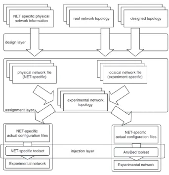
(3) SUZUKI et al.: ANYBED: A TESTBED-INDEPENDENT TOPOLOGY CONFIGURATION SYSTEM AND ITS TOOL SET. 1879. 5. Check The user checks whether the designed logical network topology is correctly built on the NET. From our experiences, time-consuming processes among all steps in network experiments are assignment and configuration. The larger the scale of NET is, the longer time in assignment is spent. The more complex the designed network topology is, the more items and parameters should be configured, and the more items or parameters are, the more time tends to be spent. 3.. Related Works and Background. StarBED [2] and Emulab [1] are typical large scale NETs. StarBED is a centralized large scale NET, which is located in NICT Hokuriku Research Center [6]. StarBED is composed of 680 PC nodes and several ATM/LAN switches for network emulation. Also, Emulab is another large scale NET and the name of its toolset. Emulab is located in University of Utah, which has 374 PCs, 40 wide-area nodes, 58 Wi-Fi nodes, and the front end to PlanetLab. Recently, NETs based on Emulab toolset are settled in several countries. DETER [7] is the most well-known large scale NET based on Emulab toolset. It focuses on experiments for research and development on cyber security technologies. Both StarBED and Emulab have produced assistant tools, which are customized for each environment [1], [2]. These tools help users to set up the basic configuration of each node, to describe experimental scenarios in an NS-like manner [8]. Most assistant tools of the NETs mainly focus on resource assignment and basic configuration support such as address assignments of each interface and setting static routes on each node. If a user wants to construct a large network topology with several routing daemons, for example, an inter-AS topology with a BGP daemon for MOAS experiments [9], he will manually set up the configuration of each BGP daemon. Moreover, these assistant tools are not designed as portable ones. Configuration files of these assistant tools and tools itself are currently customized for specific NETs. Due to this design, a user cannot freely move among various scale NETs that are suitable for his experiment. Here are the problems that we found: (1) There are no assistance tools that can construct a large network topology with several routing daemons, and (2) configuration files of existing assistant tools and assistant tools itself are not portable among NETs. To solve these problems, we design AnyBed and its toolset. 4.. Design of AnyBed. In this section, we describe the design of AnyBed. First, we describe the requirements of AnyBed. Next, we describe the details of the design.. Fig. 2. 4.1. AnyBed design.. Requirements. The design goals of AnyBed are as follows: • Reusability The reusability of logical network topologies beyond differences of physical features among NETs eases a user to quickly start experiments with the same logical network topology even if the user tries to perform the experiment in different NETs. • Portability To achieve the reusability of logical network topologies, AnyBed must have its own system portability among NETs. • Scalability To perform experiments on various scale NETs, AnyBed must work well on a large scale NET as well as small one. Also AnyBed must map a large logical network topology to the large scale NET in short time. In order to achieve these goals, we divide information for an experiment into two parts, and we adopt layered architecture that is described in the following section. 4.2. Layered Architecture. According to the requirements mentioned in Sect. 4.1, we design the layered architecture for AnyBed shown as Fig. 2. AnyBed consists of three layers: the design layer, the assignment layer, and the injection layer. In the design layer, a user designs a logical network topology and creates a logical network file according to the designed logical network topology. Similarly, each NET prepares a physical network file along with its physical network topology, that is, its facilities and the wiring among fa-.
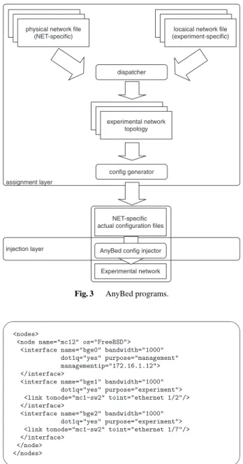
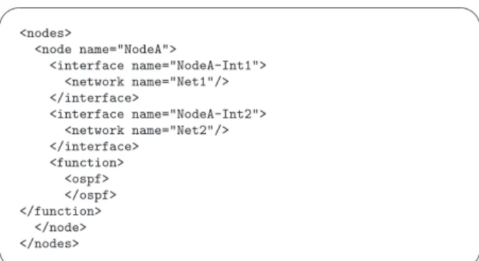
(4) IEICE TRANS. INF. & SYST., VOL.E92–D, NO.10 OCTOBER 2009. 1880. cilities. The assignment layer assigns resources such as PCs, Ethernet links, VLANs, and IP addresses. After then, assignment layer generates actual configuration files for each node and each switch. The injection layer injects actual configuration files to each node, and switch. As this layer depends on OSes and hardware specifications on each NET, we design the layer to cooperate with existing NET-specific toolsets. Because of the layered architecture, each layer is easily pluggable. It is easy to replace a component on each layer to another and to provide various components on each layer for some specific purposes. 4.3 Logical and Physical Network Topology In AnyBed, a network topology for an experiment is divided into two topologies described in XML format: logical network topology and physical network topology. A logical network topology contains the information about layer 2 and layer 3 topology of an experimental network. Since elements and attributes of a logical network topology present only the connections among logical nodes, it does not depend on a specific NET environment. On the other hand, a physical network topology shows the information about physical nodes, network bandwidth and the wiring among physical nodes. Hence, the physical network topology of each NET depends on the facilities of each NET. By using XML for the syntax of each network topology file, network topologies are not only human readable but also easily parsed by computers. Also, the consistency between a logical network topology and a physical network topology can be verified in the XML parser. As for a physical resource description format in XML, GENI project is currently standardizing GENI RSpec [10], which is based on the resource description of Emulab. However, the target of RSpec is only resource description, not topology description. 5.. Fig. 3. Implementation. In this section, we describe the implementation of assignment layer, which is the main component of AnyBed. We implemented that in Ruby 1.8.6. Supported layer2 switches are DELL PowerConnect switches and ExtremeNetworks Summit switches. Supported routing protocols are OSPF and BGP. In this section, we focus on the functions related to OSPF. The components are shown in Fig. 3. Dispatcher on the assignment layer reads both a physical network file and a logical network file, assigns the elements of the physical network topology to the elements of the logical network topology, and makes an experimental network topology with physical and logical information. Then, config generator converts the experimental network topology to actual configuration files along with the syntax of each software or each switch. In injection layer, config injector injects those actual configuration files to each PC node and switch.. Fig. 4. 5.1. AnyBed programs.. Example physical network topology.. Configuration Files for Network Topologies. In this section, we explain the design of each network file: a physical network file and a logical network file. A physical network file describes cable wiring and capability of each node and each switch. The example of a physical network topology file is shown in Fig. 4. In the first level, a <nodes> presents for node sets. A <nodes> has some <node> that present physical nodes. A <node> has some <interface> that present network interfaces on each physical node. A <interface> has some <link> that present physical links on each interface. In this example, the node named “mc12” has the management interface “bge0” and has the experimental interfaces named “bge1”, “bge2”. Each experimental inter-.
(5) SUZUKI et al.: ANYBED: A TESTBED-INDEPENDENT TOPOLOGY CONFIGURATION SYSTEM AND ITS TOOL SET. 1881. Algorithm 1 An algorithm of assigning nodes and interfaces 1: 2: 3: 4: 5: 6: 7: 8: 9: 10: 11: 12:. Fig. 5. Example logical network topology using OSPF.. 13: 14: 15: 16: 17:. procedure Assignment Main Routine sort(LogicalNodes) order by Number of Interfaces sort(PhysicalNodes) order by Number of Interfaces sort(LogicalNodes.Interfaces) order by Bandwidth sort(PhysicalNodes.Interfaces) order by Bandwidth for all LogicalNodes do l ← LogicalNode.Interfaces p ← PhysicalNode.Interfaces for all l do p.ResidualBandwidth ← p.TotalBandwidth MaximumInterface ← maximum(p) order by Bandwidth MaximumInterface.VLANID = assignNewVlanID(MaximumInterface) AverageBandwidth ← p.TotalBandwidth / l.TotalBandwidth p.ResidualBandwidth ← p.ResidualBandwidth - AverageBandwidth remove MaximumInterface from l end for end for. about nodes are mostly available in NETs. The physical network file can be converted from the inventory by a tool or manually. For example, StarBED distribute their inventory file called “starbed-resources” to users in their internal website. A user using AnyBed converts starbed-resources to AnyBed physical network file via script named “starbedresources2anybedphysical.rb”. 5.2. Fig. 6. Example logical network topology using BGP.. face connects to the port named “ethernet 1/2” and “ethernet 1/7” in the switch named “mc1-sw2”. A logical network file describes a logical network topology that the user desires to build. The example of a logical network file is shown in Fig. 5 and Fig. 6. The first example shows a part of a simple OSPF topology. The second one shows a part of a small BGP topology. AnyBed can generate both OSPF and BGP topology. Here we explain the syntax of the first example. In the first level, a <nodes> presents for node sets. A <nodes> has some <node> that presents an experimental node. A <node> has some <interface> that present network interfaces on each experimental node. A <interface> has some <network> that present network on each interface. A <function> presents that the node has routing functions line OSPF or BGP. The first example describes that the “NodeA” has interfaces named “NodeA-Int1” and “NodeAInt2”. Each interface belongs to “Net1” and “Net2”. The physical network file is basically prepared by the administrator of the NET. If the administrator does not prepare the file, a user prepares it. We consider inventory. Assignment Layer. In the assignment layer, dispatcher reads a physical network file and a logical network file. Then, dispatcher assigns physical elements to logical ones properly. The physical elements are physical nodes, network interfaces in the nodes, IP addresses, VLANs and bandwidth. In the current implementation, the criterion for properness are only fairness of bandwidth of each physical link. In a logical network file, there is a tree structure: “node” - “interface” - “network”. Similarly, in physical network file, there is a tree structure: “node” - “interface” - “link”. Dispatcher reads these structures, and then make assignment based on the algorithm shown in Algorithm 1. The reason that we adopt the simple iterative algorithm is that low computational effort is more important than bandwidth optimality. If we seek bandwidth-optimum, we must solve knapsack problem. On the large scale NET, solving knapsack problem costs high computational effort, and makes the user wait for a long time. To improve efficiency of this assignment, we must study more about a heterogeneous hardware case of “network testbed mapping problem” [11]. It is not the target of this paper however. After dispatcher finished assigning of nodes and interfaces, dispatcher assigns VLAN IDs and IP addresses to each interface, and an experimental network topology is generated as the result of resource assignment by dispatcher. Then, config generator translates from the topology to actual configuration files. On the current implementation, dispatcher and config generator are integrated; therefore, dispatcher directly generates actual configuration files. The variations of actual configuration files are as follows: rc.conf, hosts, zebra.conf,.
(6) IEICE TRANS. INF. & SYST., VOL.E92–D, NO.10 OCTOBER 2009. 1882. ospfd.conf and switch configuration files of each vendor’s syntax. Supported switch-vendors are Extreme Networks and DELL. The architecture of config generator supports plugins to generate configuration syntax for each switchvendor. If a NET has unsupported switches, a user can make a plugin for the switches. Another choice for the user is building a network “IP alias mode” of config generator. In this mode, network topology can be constructed by assigning alias IP address instead of using VLAN. This mode is also useful when a small NET has low-cost L2 switches without supporting VLAN. Supported OSes of config generator are only Linux and FreeBSD. About recent experiments in StarBED and DETER, most users performs their experiments in Linux or FreeBSD. Therefore, we support these OSes at first. Supporting many OSes, such as Microsoft Windows, is important, but beyond of this paper. 5.3 Cooperative Tools for AnyBed In this section, we describe cooperative tools for AnyBed. First, we describe about AnyBed portable toolset that makes AnyBed portable among NETs. Then, we introduce implementations of injection layer tools and implementations of design layer tools. 5.3.1 AnyBed Portable Toolset For reusability of logical network topologies among various NETs, AnyBed must have its own system portability among NETs. Each NET has its own experimental environments consisted of different hardwares and different operating systems. AnyBed must work on these environments to meet the requirement of system portability. Additionally, performing experiments among various NETs by the same tools gives users another advantage to omit learning NET’s own tools at every NET. Because of such situations, we designed a toolset called “AnyBed portable toolset” that we can be commonly used in various NETs. This toolset contains the following functions. (1) The user can use the OS which he wants without bothering with whether HDD is equipped or not and which OS was installed on experimental nodes. The tool contains servers of DHCP, TFTP, and NFS to boot clients by PXE (Preboot eXecution Environment) [12]. After nodes booted, they use NFS as its root file system, not depend on its equipped HDD. (2) The user can command each node to perform experiments without using NET’s own toolset. This tool is based on “DSH (Distributed Shell)” [13]. We can use same toolset while performing experiment on various NETs by bringing one master server that packages these toolset into the NETs. This bringing method aims to support such a use case that users can bring AnyBed-styled master server into the NETs, and can perform experiments with the toolset in the server. Generally, almost all PCs in NETs are PC/AT architecture, and support PXE boot. These PCs are quickly used as AnyBed-styled experimental nodes by the master server without care of installed OSes in node’s HDD. Accordingly,. we consider that AnyBed toolset realize system portability among various NETs. 5.3.2. Injection Layer Tools. In the injection layer, config injector injects actual configuration files to each PC node and switch. All configuration files are classified into two types. One is for PC nodes, and the other is for switches. The implementation of config injector would be different from each NET environment. For general use with AnyBed, we implement two types of config injector for PC nodes. The first one is using the modified version of “mkdiskimage” from StarBED [2]. The mkdiskimage is the environment for making memory file system image of PXE [12] boot. When a cluster node boots, the node gets two contents: memory file system image from TFTP server and tarball from FTP server. The memory file system image is mounted to root file system, and tarball is extracted there. Then, operating system reads configuration files there. In the tarball, we pack actual configuration files. The second method injects actual configuration files over NFS. The AnyBed portable toolset previously described uses this method. After a cluster node boots from PXE, the node gets actual configuration files from mounted NFS directory. For switches, we implement another type of config injector. This method communicates to switches via TELNET [14] and modifies the configuration of each switch. In this version of the program, we assume that only one user uses the switches simultaneously. Therefore, the program operate the switches as an administrative user. Aside from TELNET, the standardized mechanisms to modify the configuration of switches is “The Network Configuration Protocol”(NETCONF) [15]–[18]. NETCONF provides mechanisms to install, manipulate, and delete the configuration of switches. It employs an XML-based data encoding for the configuration data as well as the protocol messages. But, we found a problem on employing NETCONF for the config injector; only enterprise switches can support NETCONF. Low-end L2 switches that are commonly used in lab-level small NETs do not support NETCONF. 5.3.3. Design Layer Tools. We also implement some tools used for the design layer. First one is a description converter to a physical network file. This converter converts the resource description file used by StarBED’s assistant tools named “SpringOS” [4] to the format of AnyBed. Second one is filter scripts named CAIDA topology filter [19]. These scripts enables us to pick up proper size of AS relationship data from whole dataset obtained from CAIDA project [20]. CAIDA Project has measured BGP4 full route information in several backbones and analyzed an inter-AS topology according to an inferring method [21]. This AS relationship dataset shows the state of each link.
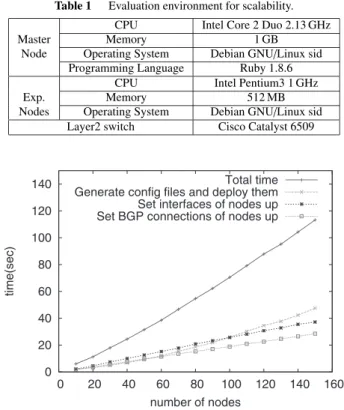
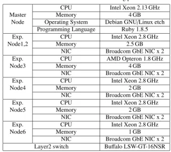
(7) SUZUKI et al.: ANYBED: A TESTBED-INDEPENDENT TOPOLOGY CONFIGURATION SYSTEM AND ITS TOOL SET. 1883. between two active ASes. These picked data are finally converted into a logical topology file of AnyBed. Using this file, users can easily build an inter-AS BGP topology like as MOAS experiments topologies [9]. Third one is a script converting a logical network file to Graphviz dot file [22]. Graphviz is open source graph visualization software. Users can visualize and confirm their designed topology by using Graphviz with this script.. Table 1 Master Node. Exp. Nodes. Evaluation environment for scalability.. CPU Memory Operating System Programming Language CPU Memory Operating System Layer2 switch. Intel Core 2 Duo 2.13 GHz 1 GB Debian GNU/Linux sid Ruby 1.8.6 Intel Pentium3 1 GHz 512 MB Debian GNU/Linux sid Cisco Catalyst 6509. 5.4 Building Experimental Network Using AnyBed The steps for the user to build experimental network with AnyBed is shown in Fig. 2. The steps are described below: 1. A NET prepares a physical network file along with its facilities and wiring. 2. A user designs a logical network topology and creates a logical network file. CAIDA topology filter facilitates generating this file. Of course, the users can edit the file manually. 3. The assignment layer of AnyBed checks the consistency of the logical network file and the physical network file. 4. The assignment layer assigns resources to the logical network topology and generates actual configuration files, if there is no inconsistency between the logical network file and the physical network file. 5. The injection layer of AnyBed injects those actual configuration files to each node and switch. Compared to the manual steps described in Sect. 2.2, AnyBed and its toolset automate most processes: some parts of design, assignment, configuration, and injection. The detail evaluation and verification are described in the following sections. 6.. Evaluation. In this section, we describe the evaluation result of the AnyBed implementation. We conducted the following evaluations: scalability to the number of nodes and workload reduction. 6.1 Scalability to the Number of Nodes In this section, we see if AnyBed can deal with large scale network and many nodes. Because we do not have a real large scale NET, we use StarBED for our scalability evaluation; which is the well-known large-scale centralized NET that composed of 680 nodes. We describe evaluation environment. We used 150 experimental nodes on StarBED and 1 master node. As for a typical user on StarBED, he uses about 50 up to 150 nodes for one experiment. In DETER, recent experiments [9], [23], [24] need roughly 10 to 100 nodes. We think that evaluating AnyBed using up to 150 nodes is enough for typical uses. The specifications of nodes are described in Table 1. In this evaluation, we described the logical network file. Fig. 7 Time consumption of building experimental network under different number of nodes.. where nodes had BGP links each other. This BGP topology was based on the AS topology of the Internet using the dataset published by CAIDA [20]. We extracted top ASes and its related networks from this dataset in order of the number of BGP peers that ASes have. The number of extracted ASes depended on the number of usable nodes in NET. Using this topology, we made an experimental network and measured the time consumption with changing the number of nodes from 10 to 150 on the environment. In this evaluation, because 1 AS in the dataset corresponded with 1 node in NET, we could only emulate a part of the whole topology. We measured times taken by below procedures. (1) We ran dispatcher on the master node to generate actual configuration files, and then deployed them to experimental nodes. (2) After deployed, we set interface of the experimental nodes up. (3) Finally, we set BGP connections of each node up. Figure 7 shows that the total time consumption increased linearly up to 150 nodes. However, the time generating configuration files and deploying them does not seem to linearly but exponentially. The reason that the curve described in the exponential function was that the BGP topology was nearly full meshed and the number of subnets and interfaces increased in the order of O(n2 ). The number affected the time of assigning resources and the time of generating configuration files, we considered. On 150 nodes, the total time consumption of dispatcher was 113 seconds. Along with this evaluation, we conclude that (1) AnyBed can ease the overhead of describing configuration files in the order of magnitude, and (2) it can generate con-.
(8) IEICE TRANS. INF. & SYST., VOL.E92–D, NO.10 OCTOBER 2009. 1884 Table 2 Verification environment for reusability and workload reduction (homogeneous cluster). Node#1 CPU to Memory Node#17 NIC Layer2 switch. Intel Pentium3 1.4 GHz 1024 MB Broadcom BCM5703X(1000 Mbps) x 2 DELL PowerEdge1655MC Switch. Table 3 Verification environment for reusability and workload reduction (heterogeneous cluster). Node#1 to Node#3. CPU Memory NIC. Node#4 to Node#7. CPU Memory NIC. Layer2 switch. Table 4. Fig. 8. Intel Pentium3 450 MHz 256 MB Intel Pro 10/100B/100+(100 Mbps) 3Com 3c905B-TX(100 Mbps) Intel Pentium3 900 MHz 256 MB 3Com 3c905B-TX(100 Mbps) Netgear GA620(1000 Mbps) FoundryNetworks EdgeIron4802F ExtremeNetworks Summit48 ExtremeNetworks Summit5i. Table 5 Master Node Exp. Node1,2 Exp. Node3. Evaluation result of usability and workload reduction. Homogeneous. Heterogeneous. Exp. Node4. Num. of nodes Num. of config. file in AnyBed Size of config. file in AnyBed. 17 2 10671 Byte. 7 2 6549 Byte. Exp. Node5. Num. of actual config. files Size of actual config. files. 31 33957 Byte. 30 39191 Byte. Exp. Node6. Average time of building network. 137 sec. 135 sec. figuration files and can deploy them on a large scale NET in enough short time. 6.2 Workload Reduction We measured the time until AnyBed finished building the experimental network. These sequence was repeated 10 times to calculate the average. In addition, we compared number of configuration files, the size of configuration files on two PC clusters. One cluster was composed of 17 servers that have homogeneous specs. Another cluster had 7 heterogeneous servers. Equipments on each PC cluster are described in Table 2 and Table 3. The verification result is described in Table 4. First, we discuss the size and the number of configuration files. We used the logical network file that size was 3,377 Bytes on both clusters. About the size of physical network file, the size of the file in homogeneous cluster was 7,294 Bytes, and that of heterogeneous cluster was 3,172 Bytes. On the other hand, the total size of actual configuration files was 33,957 Bytes in heterogeneous PC cluster. The configuration files that a user had to create were only two files in both PC clusters, that is, the logical network file and the physical network file. On the other hand, the number of the actual configuration files in homogeneous cluster is 31, and the number in heterogeneous cluster is 30. Without AnyBed, the user has to write the total size and total number of the file by hand or by script. Second, we dis-. Evaluation topology for routing performance.. Evaluation environment for routing performance. CPU Memory Operating System Programming Language CPU Memory NIC CPU Memory NIC CPU Memory NIC CPU Memory NIC CPU Memory NIC Layer2 switch. Intel Xeon 2.13 GHz 4 GB Debian GNU/Linux etch Ruby 1.8.5 Intel Xeon 2.8 GHz 2.5 GB Broadcom GbE NIC x 2 AMD Opteron 1.8 GHz 4 GB Broadcom GbE NIC x 2 Intel Xeon 2.8 GHz 2 GB Broadcom GbE NIC x 2 Intel Xeon 2.8 GHz 2 GB Broadcom GbE NIC x 2 Intel Xeon 2.8 GHz 1 GB Broadcom GbE NIC x 2 Buffalo LSW-GT-16NSR. cuss the time of building experimental network. The time of building experimental network was fewer than 140 seconds on both clusters. We think that 140 seconds are short enough compared with building it by hand. 6.3. Decline of Routing Performance. In this section, we discussed the decline of routing performance when a user employs AnyBed. We evaluated the differences of routing performance on two same topologies: one was built by AnyBed, and the other was built by hand. Figure 8 shows these topologies. On these topologies, we assigned the same PC for each node. Equipments on each PC are described in Table 5. On each topology, we measured routing performance 10 times from node1 to node6 by iperf. The result of the measurement showed that both topologies had the same routing performances. In both cases, measured routing performance was 914 Mbps. The result means that AnyBed does not cause decline of routing performance. 7.. Verification. In this section, we describe the verification result of the AnyBed implementation. We conducted the following verifications and evaluations: topology reusability, system portability, and scalability to the number of nodes..
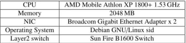
(9) SUZUKI et al.: ANYBED: A TESTBED-INDEPENDENT TOPOLOGY CONFIGURATION SYSTEM AND ITS TOOL SET. 1885 Table 6. 7.1 Topology Reusability In this section, we verify the functions of AnyBed. In the verification, we prepared two PC clusters that their hardware equipment is different from each other. On these two clusters, we built the same network topology by AnyBed to verify topology reusability. Also we compared number of configuration files, the size of configuration files and the average time spend for building the network to verify workload reduction. Then, we verified system portability of AnyBed using another two different PC clusters. Equipments on each PC cluster are described in Table 2 and Table 3. The former PC cluster was homogeneous, that is, it was composed of 17 blade servers where each blade server had the same hardware and software spec. On the other hand, the latter PC cluster had heterogeneous nodes, that is, it was constructed with different spec PCs and several vendors’ switches. The homogeneous PC cluster was comprised of 17 blade servers and a layer 2 switch made by Dell. We used one server for DHCP, FTP server, and the other for building experimental network. These cluster nodes were connected with each other by 6 layer2 switches. Because all equipped NICs were PXE-capable, we used PXE boot and mkdiskimage for config injector. The heterogeneous PC cluster was composed of 7 nodes. Node#1 to node#3 and node#4 to node#7 were different in the type of NIC. Therefore, bandwidth and the name of network interface in operating system were different between two groups. In the heterogeneous PC cluster, we could not use PXE boot for config injector because all equipped NICs were not PXE-capable. Instead of PXE boot, we used NFS for config injector. On these two PC clusters, we gave the same logical network file that 7 routers were connected with full mesh links, then verified whether the same experimental network topologies were built or not. To investigate network topologies, we logged in to Zebra OSPF daemon via telnet, and got the routing information by executing “show ip ospf route” command [25]. 7.2 System Portability Then, we verified system portability of AnyBed using another two different PC clusters. One cluster had 32 blade servers described in Table 6 and another cluster had 32 1U servers described in Table 7. At first, after we connected the master server including the AnyBed portable toolset, we built BGP topology on the first cluster using the toolset. Secondly, we disconnected the master server and brought it to the facilities that another cluster was located. Then, after we connected it to another cluster, we had quickly rebuilt the same topology with regenerating actual configuration files. This verification shows that AnyBed toolset has system portability. According to the results of verifications, we conclude that AnyBed enables a topology to reuse among 4 NETs and. Verification environment for system portability (Cluster#1).. CPU Memory NIC Operating System Layer2 switch. Table 7. AMD Mobile Athlon XP 1800+ 1.53 GHz 2048 MB Broadcom Gigabit Ethernet Adapter x 2 Debian GNU/Linux sid Sun Fire B1600 Switch. Verification environment for system portability (Cluster#2). CPU Memory Operating System Layer2 switch. Intel Pentium3 1 GHz 512 MB Debian GNU/Linux sid Cisco Catalyst 6509. that AnyBed can reduce the workload of building experimental network on NET. The result of evaluation and verification shows that AnyBed has achieved the design goals described in Sect. 4.1. First, Sect. 7.1 has described about the reusability of network topology. Then, we have described the portability of AnyBed in this section. About the scalability of AnyBed, the result in Sect. 6.1 has shown that AnyBed is enough scalable for typical experiments. 8.. Discussion. First, we discuss scalability in massive network topology consisting of virtual nodes. Then, we discuss consistency of the constructed network with AnyBed and testbed-oriented supportive tools. 8.1. Scalability in Massive Network Topology Consisting of Virtual Nodes. Recently, advances of virtualization technologies increase the number of nodes in NETs by several times. Anticipating that a user would use AnyBed in thousands of virtual nodes, we have tested the scalability of AnyBed. In the case of 10,000 virtual nodes, AnyBed and XENebula toolset [26] took 2.5 days to build a network topology. This result shows that current AnyBed implementation is not scalable in massive network topology. We will analyze bottleneck points, and improve the scalability in our future work. With use of virtualization technologies, we consider that it will become more common for network researchers to perform experiments with over hundreds of virtual nodes in lab-level NETs with AnyBed. However, in the massive environment, there are still problems in addition to the scalability: node control, measurement, anomaly detection, and so on. These are all our future works. 8.2. Consistency of the Constructed Network with AnyBed and Testbed Oriented Supportive Tools. Checking the consistency of the constructed network topology is one of issues on experiments on NET. The consistency in this context means that the network is certainly constructed as the user intended. Due to the numerous network.
(10) IEICE TRANS. INF. & SYST., VOL.E92–D, NO.10 OCTOBER 2009. 1886. nodes, the consistency check is tedious work, too. The inconsistency will be caused not only by mis-configuration of AnyBed, but also by mis-configuration of VLAN and/or assigned nodes by testbed oriented supportive tools. In our future work, we have to develop a scalable consistency check component that can let experimenters narrow down causes of inconsistency. 9.. Conclusion. Through our experiences of experiments on NETs, we pointed out advantages for the case that an experimental network topology and its configuration files should be portable across NETs. With consideration to the portability, we analyzed the steps to perform experiment on NETs. We particularly focused on the step to build experimental networks since it is time-consuming among all the steps. Considering procedures in the step to build experimental networks, we designed AnyBed architecture. Then, we implemented assignment layer and injection layer of AnyBed. We also verified and evaluated the assignment layer implementation. The results of the verification and evaluation showed that AnyBed well automated the steps to construct an experimental network topology on various NETs. AnyBed can expedite the time spent building 50 AS topology, from 4 days in manual to 30 seconds in AnyBed. The implementation of AnyBed is available from Sourceforge.net [27]. References [1] B. White, J. Lepreau, L. Stoller, R. Ricci, S. Guruprasad, M. Newbold, M. Hibler, C. Barb, and A. Joglekar, “An integrated experimental environment for distributed systems and networks,” Proc. Fifth Symposium on Operating Systems Design and Implementation, 2002. [2] T. Miyachi, K. Chinen, and Y. Shinoda, “Automatic configuration and execution of internet experiments on an actual node-based testbed,” Proc. 2nd International IEEE/Create-Net Conference on Testbeds and Research Infrastructures for the Development of Networks and Communities (TridentCom), pp.274–282, 2005. [3] “Emulab software distributions.” http://www.emulab.net/software.php3 [4] T. Miyachi, K. Chinen, and Y. Shinoda, “StarBED and SpringOS: Large-scale general purpose network testbed and supporting software,” Proc. International Conference on Performance Evaluation Methodlogies and Tools (Valuetools) 2006, 2006. [5] M. Oe, Y. Kadobayashi, and S. Yamaguchi, “An implementation of a hierarchical IP traceback architecture,” Proc. IPv6 Workshop, SAINT 2003, Orland, USA, 2003. [6] “NICT Hokuriku research center.” http://starbed.nict.go.jp/ [7] T. Benzel, R. Braden, D. Kim, C. Neuman, A. Joseph, K. Sklower, R. Ostrenga, and S. Schwab, “Design, deployment, and use of the DETER testbed,” Proc. DETER Community Workshop 2007, 2007. [8] Information Sciences Institute, “NS-2 network simulator,” Software Package, 2003. http://www.isi.edu/nsnam/ns/ [9] S.P.G. Carl, G. Kesidis, and P.S.U.B. Madan, “Preliminary BGP Multiple-Origin Autonomous Systems (MOAS) experiments on the DETER testbed,” Proc. Deter Community Workshop 2006, 2006. [10] “GENI Rspec.” http://groups.geni.net/geni/attachment/wiki/ GeniRspec/rspec-draft-v0.5.doc [11] R. Ricci, C. Alfeld, and J. Lepreau, “A solver for the network testbed mapping problem,” ACM SIGCOMM Computer Communications. Review, vol.33, no.2, 2003. [12] “Intel corporation, Preboot Execution Environment (PXE) specifiction version 2.1,” 1990. [13] J. Uekawa, “Dsh - dancer’s shell / distributed shell.” http://www.netfort.gr.jp/˜dancer/software/dsh.html [14] J. Postel and J. Reynolds, “Telnet protocol specification, RFC854,” 1983. [15] R. Enns, ed. and J. Networks, “NETCONF configuration protocol, RFC4742,” 2006. [16] M. Wasserman, ThingMagic, T. Goddard, and I. ICEsoft Technologies, “Using the NETCONF configuration protocol over Secure SHell (SSH), RFC4742,” 2006. [17] T. Goddard and I. T. Inc., “Using NETCONF over the Simple Object Access Protocol (SOAP), RFC4742,” 2006. [18] E. Lear, C. Systems, and K. Crozier, “Using the NETCONF protocol over the Blocks Extensible Exchange Protocol (BEEP), RFC4742,” 2006. [19] H. Hazeyama, M. Suzuki, S. Miwa, D. Miyamoto, and Y. Kadobayashi, “Outfitting an Inter-AS topology to a network emulation TestBed for realistic performance tests of DDoS countermeasures,” Proc. Workshop on Cyber Security Experimentation and Test (CSET’08), 2008. [20] CAIDA, The cooperative association for Internet data analysis, “The CAIDA AS Relationships Dataset.” http://www.caida.org/data/active/as-relationships/ [21] X. Dimitropoulos, D. Krioukov, M. Famenkov, B. Huffaker, Y. Hyun, K. Claffy, and G. Riley, “AS relationships: Inference and validation,” ACM SIGCOMM Computer Communication Review (CCR), vol.37, no.1, pp.29–40, 2007. [22] “Graphviz - Graph visualization software.” http://www.graphviz.org/ [23] J. Mirkovic, B. Wilson, A. Hussain, S. Fahmy, P. Reiher, R. Thomas, and S. Schwab, “Automating ddos experimentation,” Proc. Deter Community Workshop on Cyber Security Experimentation and Test 2007, 2007. [24] Y.-L. Huang, Y. Huang, J. Tygar, H. Lin, L.Yeh, H. Tsai, K. Sklower, S. Shieh, C. Wu, P. Lu, S. Chien, Z. Lin, L. Hsu, C.W. Hsu, C.T. Hsu, Y. Wu, and M. Leong, “SWOON: A testbed for secure wireless overlay networks,” Proc. CyberSecurity Experimentation and Test (CSET) Workshop, 2008. [25] “GNU zebra.” http://www.zebra.org/ [26] S. Miwa, M. Suzuki, H. Hazeyama, S. Uda, T. Miyachi, Y. Kadobayashi, and Y. Shinoda, “Building mimetic internet—A trial to emulate inter—AS networks,” Internet Conference 2007, pp.41– 48, 2007. [27] M. Suzuki, “AnyBed: A testbed-independent topology configuration tool.” http://sourceforge.net/projects/anybed/. Mio Suzuki received his M.E. degree of Science and Technology (NAIST), Japan, in 2004. He is currently a technical engineer in National Institute of Information and Communications Technology(NICT), Japan. His research interests include internet emulation, network operation, network security..
(11) SUZUKI et al.: ANYBED: A TESTBED-INDEPENDENT TOPOLOGY CONFIGURATION SYSTEM AND ITS TOOL SET. 1887. Hiroaki Hazeyama received his Ph.D. degree in Engineering from Nara Institute of Science and Technology (NAIST), Japan, in 2006. He is currently an assistant professor in the Graduate School of Information Science, NAIST. His research interests include network operation, network security, and large-scale network testbed.. Daisuke Miyamoto received his M.E. degree in Information Science from Nara Institute of Science and Technology (NAIST), Japan, in 2002. He is currently a researcher in NAIST. His current interests include web application security especially countermeasures of web spoofing.. Shinsuke Miwa received his Ph.D. degree in Information Science from Japan Advanced Institute of Science and Technology (JAIST), Japan, in 1999. He is currently a researcher in Information Security Research Center, National Institute of Information and Communications Technology (NICT), Japan. His current research interests include cyber-security using virtualization technologies and Internet emulation. He is a member of USENIX and ACM.. Youki Kadobayashi received his Ph.D. degree in Computer Science from Osaka University in 1997. He is currently an Associate Professor in the Graduate School of Information Science, Nara Institute of Science and Technology, Japan. His research interests include IP traceback, content internetworking, overlay networks, quality of services in the applicationlayer, middleware security, and secure operating systems. He is also a member of IPSJ..
(12)
図
+4
関連したドキュメント
Laplacian on circle packing fractals invariant with respect to certain Kleinian groups (i.e., discrete groups of M¨ obius transformations on the Riemann sphere C b = C ∪ {∞}),
The edges terminating in a correspond to the generators, i.e., the south-west cor- ners of the respective Ferrers diagram, whereas the edges originating in a correspond to the
Moreover, to obtain the time-decay rate in L q norm of solutions in Theorem 1.1, we first find the Green’s matrix for the linear system using the Fourier transform and then obtain
Eskandani, “Stability of a mixed additive and cubic functional equation in quasi- Banach spaces,” Journal of Mathematical Analysis and Applications, vol.. Eshaghi Gordji, “Stability
Finally, we give an example to show how the generalized zeta function can be applied to graphs to distinguish non-isomorphic graphs with the same Ihara-Selberg zeta
We show that a discrete fixed point theorem of Eilenberg is equivalent to the restriction of the contraction principle to the class of non-Archimedean bounded metric spaces.. We
It turns out that the symbol which is defined in a probabilistic way coincides with the analytic (in the sense of pseudo-differential operators) symbol for the class of Feller
In order to be able to apply the Cartan–K¨ ahler theorem to prove existence of solutions in the real-analytic category, one needs a stronger result than Proposition 2.3; one needs
