Doctoral Thesis
Study on Harmonic Structure Design and Deformation
Mechanism in SUS304L Austenitic Stainless Steel
Ritsumeikan University
Graduate School of Science and Engineering
Doctoral Program in Integrated Science and Engineering
ZHANG Zhe
Mechanism in SUS304L Austenitic Stainless Steel
December, 2013
Doctor of Philosophy
Zhe ZHANG
Committee in charge:
Professor Kei AMEYAMA, Chair
Professor Masao SAKANE
Professor Akira UENO
Doctoral Program in Integrated Science and Engineering
Graduate School of Science and Engineering
i
Abstract
Study on Harmonic Structure Design and Deformation Mechanism in SUS304L Austenitic Stainless Steel
by Zhe ZHANG
Doctoral Program in Integrated Science and Engineering Graduate School of Science and Engineering
Ritsumeikan University
Academic Advisor: Professor Kei AMEYAMA
Owing to the excellent corrosion resistance and oxidation resistance, austenitic stainless steels have been widely used in the chemical and petrochemical industry. However, low yield strength is the major drawback of austenitic stainless steel. Grain refinement is a well known and attractive method of strengthening structural metallic materials. However, ultrafine-grained (UFG) materials are characterized by low tensile ductility at room temperature because of plastic strain instability in the early stage of deformation. Both strength and ductility are the important mechanical properties for industrial applications. Bimodal grain size distribution is a useful strategy to enhance ductility. However, the outcome properties span a relatively wide range depending on the microstructural variations.
ii
Recently, professor Ameyama and co-workers proposed a powder metallurgy (PM) based approach to create a novel bimodal microstructure design called “harmonic structure”. Effectively, harmonic structure is a periodic “nano and heterogeneous bimodal structure” consisting of coarse-grained (CG) areas (or “cores”) enclosed in a three-dimensional continuously connected network of UFG structure (or “shell”).The concept of harmonic structure design has been successfully applied in a variety of pure metals and metallic alloys by mechanical milling (MM) and subsequent powder metallurgy (PM) process. All these materials demonstrate a winning combination of improved strength and ductility as compared to their coarse-grained as well as ultrafine-grained counterparts.
The present dissertation describes the work that has been carried out to obtain a better understanding of the manufacture, mechanical properties, deformation and fracture mechanism of harmonic-structured austenitic stainless steel. Plasma rotating electrode process (PREP) powders, which are characterized by low oxygen content and spherical powder shape, are applied in present work. The harmonic structure has been synthesized in SUS304L stainless steels produced by mechanical milling (MM) and subsequent spark plasma sintering (SPS) process. Martensite transformation and subsequent austenite reversion plays an important role on grain refinement in the SUS304L steels. The volume fraction of UFG can be adjusted by controlling mechanical milling conditions.
Compared to the conventional homogeneous CG and UFG bulks, the harmonic-structured SUS304L steels demonstrate a superior combination of high
iii
strength, large uniform elongation, and large total elongation. Also, the harmonic-structured SUS304L steels exhibit good reproducibility, higher average strength and ductility simultaneously as compared to the steels having same grain size and volume fraction but irregular CG and UFG spatial distribution.
Through comparing the tensile deformation of the specimens having different bimodal structure heterogeneity and topology, it is concluded that the three-dimensional continuous connected network of UFG structure is conducive to restraining strain localization during mechanical loading. The suppressed strain localization leads to postpone the plastic strain instability and delay the neck formation. Therefore, the ductility, in particular uniform elongation in tension of harmonic bimodal structured SUS304L steels is superior to the value of heterogeneous bimodal structured ones. The ductility of bimodal structured materials can be improved by controlling the CG and UFG spatial distribution. “Harmonic structure design” is proposed to be an effective strategy to achieve outstanding mechanical properties.
Since water-atomization is the most common technique for producing low-cost metal powders, water-atomized steel powders have been widely used in industry. Therefore, “harmonic structure design” is also attempted to synthesize in water-atomized SUS304L powder steels. However, owing to the high oxygen content in water-atomized powders, a large amount of SiO2 particles precipitate in the UFG region of sintered compacts.
SiO2 particles tend to impair the inter-particle bonding and result in poor ductility.
Therefore, in order to improve mechanical properties, it is necessary to reduce oxidized contaminations in the PM steels.
iv
Acknowledgements
I would like to take this opportunity to express my most sincere gratitude to Professor Kei Ameyama, who taught and gave me invaluable advice and generous help through these six years at Ritsumeikan University. Although I cannot study in the university at work time, he still helped me apply for doctoral program, gave me supervision in his spare time. I would like to remember his inculcation for clarify the critical logical relation in the research forever. His guidance and encouragement enabled me to become stronger and wiser, in both academic matters and personal growth.
I am grateful to the company, Dainippon Screen MFG. Co., Ltd., who gave me scholarship for the study of master program and provided me the work opportunity in Japan. Special thanks to Mr. Yoshiyuki Nakazawa and Mr. Kazuhiko Asada for their patient guidance for my work in the company and the convenience for my study.
Special thanks to Associate Professor Hiroshi Fujiwara (now in Doshisha University, Kyoto) for his selfless support in texture and microstructural analysis and his constant encouragement and fruitful suggestions. I also wish to thank Professor Akira Ueno (Ritsumeikan University) for his kind support and useful suggestions in fractographical analysis on fracture mechanism of harmonic-structured stainless steels.
v
Dmitry Orlov and Dr. Sanjay Kumar Vajpai (Global Innovation Research Organization, Ritsumeikan University) for excellent advices to use EBSD and TEM equipments and useful comments and advice on my research and journal paper preparation.
I am also heartily thankful to Professor Masao Sakane (Ritsumeian University) and Professor Xu Chen (Tianjin University), who gave me this opportunity to study in Japan and encouragement during my study.
I owe my most sincere gratitude to all of members in Ameyama laboratory, such as Dr. Eji Ota, Dr. Tatsuya Sekiguchi, Kouryu Kawadani, Masashi Nakatani, and so on, who have gave me many useful advice on my research and usual life in Japan. Special thanks to Bo Tong for his wonderful assistance.
My heartfelt thanks to all my friends, their encouragement and company kept my spirits high and joyful. Many thanks to all the other people not mentioned, but to whom I am grateful for their kind assistance in one way or another during the past six years.
Finally, I express my profound gratitude to my parents for their sacrifices, constant support, understanding and encouragement extended during my life in Japan.
December 2013 Kyoto, Japan Zhe ZHANG
vi
Table of Contents
Abstract………..……….. i Acknowledgements………..…..…...…. iv Table of Contents………...… vi Chapter 1 Introduction... 1 1.1 Background……….… 1 1.2 Objective of dissertation…………...………...…... 4 1.3 Outlet of dissertation…..……….... 5Chapter 2 Literature Review………. 7
2.1 Austenitic stainless steels………...……….…… 7
2.2 Powder metallurgy……….. 9
2.2.1 Manufacture and characteristics of metal powders………...…… 10
2.2.2 Limitations of powder metallurgy……….…… 18
2.3 Ultrafine-grained (UFG)/ nanocrystalline (NC) metals………... 19
2.3.1 Manufacture processes of UFG/NC metals………..……… 19
2.3.2 Grain refining mechanisms of metals by SPD……….. 23
2.3.3 Mechanical properties of UFG/NC metals……… 24
2.3.4 Deformation mechanisms of UFG/NC metals……….……. 33
2.3.5 Limitations of UFG/NC metals………. 35
vii
2.4 Research progress of harmonic-structured metals………..…….. 44
References………..………...……. 46
Chapter 3 Experimental Procedure…...………. 60
3.1 Mechanical milling (MM)……….60
3.2 Sintering………. 63
3.2.1 Spark plasma sintering (SPS)……….……….…………. 63
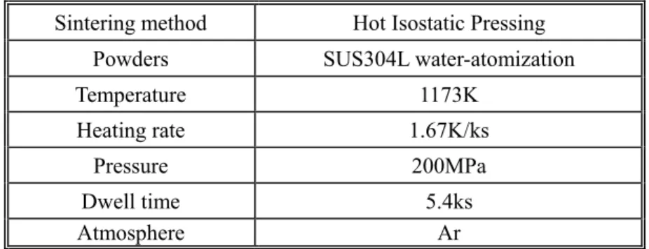
3.2.2 Hot isostatic pressing (HIP)………..……… 65
3.3 Characterizations……….………. 67
3.3.1 X-ray diffraction (XRD)………..……….. 67
3.3.2 Scanning electron microscopy (SEM)……….……….. 68
3.3.3 Electron backscatter diffraction (EBSD)………..………. 70
3.3.4 Transmission electron microscopy (TEM)……… 73
3.4 Mechanical properties……….…….. 74
3.4.1 Vickers hardness test……….. 74
3.4.2 Tensile test………...……….. 75
References………..………...…………. 76
Chapter 4 Microstructure and Mechanical Properties of SUS304L Compacts with Harmonic Structure……….………..……… 78
4.1 Introduction……….. 78
4.2 Experimental procedure……… 79
4.3 Results………....……….. 81
viii
4.3.2 Microstructural characteristics of the sintered compacts………..… 84
4.3.3 Mechanical properties of harmonic-structured compacts……..…..……..… 88
4.4 Discussion………..………...……….. 91
4.4.1 Control of microstructure in harmonic-structured SUS304L steels during fabrication ……….………...…...………….... 91
4.4.2 Correlation between microstructure and mechanical properties in harmonic-structured SUS304L steels………..………..………....……..… 94
4.4.3 Benefits of harmonic structure design concept for the control of SUS304L steels performance…...………..………...……..…. 96
4.5 Conclusions………...…….……….. 97
References………..………….... 98
Chapter 5 Deformation and Fracture Mechanism of SUS304L Compacts with Harmonic Structure………...……. 100
5.1 Introduction……… 100
5.2 Experimental procedure……….………. 102
5.3 Results………..……….. 102
5.3.1 Mechanical properties of harmonic and heterogeneous bimodal structured compacts………..….. 102
5.3.2 Deformation behavior of harmonic and heterogeneous bimodal structured compacts………..…..… 107
5.3.3 Fracture behavior of harmonic and heterogeneous bimodal structured compacts……….………... 115
ix
5.4.1 Improve ductility through the control of bimodal structure heterogeneity and
topology………. 120
5.4.2 Deformation mechanism of harmonic-structured SUS304L compacts…... 122
5.4.3 Fracture mechanism of harmonic-structured SUS304L compacts……….. 124
5.5 Conclusions………..…….. 129
Reference………..……… 131
Chapter 6 Effects of SiO2 Particles on Deformation of SUS304L Powder Compacts with Bimodal Structure……….………...……...……. 134
6.1 Introduction………..……….. 134
6.2 Experimental procedure……….………..………..……. 134
6.3 Results and discussion………..………..………… 136
6.3.1. Microstructure of the MM-HIP compacts…………..………..…….. 136
6.3.2 Deformation and fracture of the MM-HIP compacts………..……. 144
6.4 Conclusions………..…..……… 152
References…….…….…………..………..……….. 153
Chapter 7 Conclusions and Future Work……….……… 155
7.1 Overall conclusions………...…………. 155
7.2 Further work……….……….. 160
Appendix………...………. 161
Curriculum vita………...……….. 161
1
Chapter 1 Introduction
1.1 Background
Austenitic stainless steels are the most common and familiar types of stainless steels. Due to their extremely corrosion resistance and oxidation resistance, these materials can be successfully used for chemical processing equipment, for food, dairy, and beverage industries, for heat exchangers, and for the milder chemicals.
However, austenitic stainless steels are in general of rather low yield strength. In order to remain the material of choice for these component manufacturers, the strength of stainless steels should be improved. It is well-known that strengthening arising from grain refinement is usually governed by the Hall-Petch relation, which projects a continuous rise of strength with decreasing grain size. Therefore, in order to enhance the strength of materials, the past decade has witnessed a surge in research and development worldwide to drive the grain sizes of bulk metals and alloys down into the so-called ultrafine-grained (UFG) and nanocrystalline (NC) regime. UFG/NC steels demonstrated superior strength and hardness compared to their coarse-grained (CG) counterparts. Besides strength, wear resistance, pitting resistance and resistance to cavitation and cavitation-erosion can also be improved by reducing grain size. Furthermore, damage/intergranular precipitation and segregation caused by irradiation is believed to be reduced in UFG/NC stainless steels, because the copious amounts of grain boundaries enable irradiation-generated point defects to annihilate.
2
However, for some applications, an appreciable uniform elongation under tensile stresses is required, but is rarely available in traditional homogeneous UFG/NC materials. The limited ductility of UFG/NC materials is a major barrier to their widespread commercial usage. Briefly, the reason for the inadequate ductility is prone to instabilities on plastic deformation, which leads to early strain localization and failure and also due to a reduced ability of the materials to accommodate the progression of cracks by extensive plastic deformation.
Therefore, it is imperative to achieve the improvement of both the mechanical properties, i.e. a combination of high strength and good ductility, in the UFG/NC steels to make them really attractive for the aforementioned applications. A key to meeting the ductility challenge is to use stabilizing mechanisms to overcome the instabilities that threaten the tensile elongation of UFG/NC metals and alloys. Bimodal (or multi-modal) grain size distribution is a useful strategy to enhance ductility, which could achieve simultaneously good yield strength and fairly large uniform (and total) elongation. The UFG/NC matrix in the bimodal microstructure provides the high strength, while the relatively large coarse grains contribute to the ductility. However, the exact distributions of the grain size, grain shape, and spatial locations depend on many processing parameters and may be difficult to reproduce. The outcome properties therefore span a relatively wide range depending on the microstructural variations. The overall of material response is tricky to predict and model.
3
Figure 1.1 Schematic of a harmonic-structured material.
Recently, professor Ameyama and co-workers proposed another powder metallurgy (PM) based approach to create a novel bimodal microstructure design called “harmonic structure”. Effectively, this is a regular “nano and heterogeneous bimodal structure” consisting of CG areas (or “cores”) enclosed in a three-dimensional continuously connected network of UFG structure (or “shell”), see Fig.1.1.The concept of harmonic structure design has been successfully applied in a variety of materials, such as pure Ti, Cu, alloy Ti-6Al-4V, and two-phase steel SUS329J1. All these materials demonstrated a winning combination of improved strength and ductility as compared to their CG as well as UFG counterparts. However, there is still no investigation of harmonic-structured austenitic stainless steel. The effect of the three-dimensional continuously connected network of UFG structure on improved ductility has not been revealed yet.
4
1.2 Objective of Dissertation
This dissertation describes the work that has been carried out to obtain a better understanding of the manufacture, mechanical properties, deformation and fracture mechanism of austenitic stainless steel having “harmonic structure”. The fabrication and characterization of harmonic structure in SUS304L stainless steel by the PM approach, which involves the mechanical milling of the steel powder followed by its consolidation using conventional sintering process, such as spark plasma sintering (SPS) and hot isostatic pressing (HIP).
In the present dissertation, the follow contents will be discussed:
(i) Fabrication of harmonic-structured SUS304L steels and microstructural evolution during mechanical milling and sintering process.
(ii) Relationship between microstructure and mechanical properties and superiorities of the harmonic-structured SUS304L steels when compared to those of “homogeneous” CG and UFG steels and conventional “heterogeneous bimodal structured” steels.
(iii) Role of the three-dimensional continuous network of UFG structure in improving the ductility, in particular uniform elongation in tension.
(iv) Deformation and fracture mechanism of harmonic-structured SUS304L steels. (v) Mechanical properties, deformation and fracture mechanism of mechanical milled
5
1.3 Outlet of Dissertation
The present dissertation consists of seven chapters as follows:
Chapter 2 presents a brief review on characteristics of austenitic stainless steels and powder metallurgy including fabrication processes of the metal powders, since austenitic stainless steel powders and powder metallurgy method are applied to fabricate the harmonic-structured steels in present thesis. Subsequently, a brief overview of the recent progress of bulk nanostructured materials including synthesis methods and mechanism of UFG/NC structure, the mechanical properties and limitation of bulk UFG/NC metals, the possible strategies to enhance tensile ductility of UFG/NC metals are illustrated. Finally, the research progress of “harmonic structure designed” materials is introduced.
The experimental procedure in the present study is described in Chapter 3. The fabrication of harmonic-structured SUS304L steels by mechanical milling and consolidating process, samples preparation for microstructural observations as well as mechanical properties tests are introduced in detail.
Chapter 4 presents the synthesis method of “harmonic structure” in SUS304L steels by MM-SPS method using the “clean and spherical” PREP powders. The microstructure evolution and mechanical properties of harmonic-structured SUS304L steels comparing with conventional CG and UFG bulk are discussed.
A general discussion is presented in Chapter 5 which focuses on the role of the three-dimensional continuous network of UFG structure in improving the ductility, in particular uniform elongation in tension. The tensile property of the bimodal structured SUS304L steels having different spatial distribution of CG and UFG components is
6
compared. The superiorities of “harmonic structure designed” materials on mechanical property are revealed. The deformation and fracture mechanism of harmonic-structured SUS304L steels are also illustrated.
Due to the high volume production and low-cost, water-atomized steel powders are common applied in industry. Therefore, SUS304L water-atomized powders are also attempted to synthesize “harmonic structure designed” SUS304L steel in Chapter 6. However, owing to high oxygen content in water-atomized powders, a large amount of SiO2 particles tend to precipitate in the UFG region of sintered compacts. The effects of
SiO2 particles on deformation and fracture behavior of SUS304L water-atomized
powder steels are discussed. SiO2 particles are harmful to the inter-particle bonding
which results in poor ductility during mechanical loading. In order to obtain enhanced mechanical properties, the surface silicon oxide particles should be reduced.
Chapter 7 summarizes the main findings and conclusions in this study. It also proposes some future work that should be carried out in order to obtain further understanding in this research area.
7
Chapter 2 Literature Review
2.1 Austenitic Stainless Steels
Stainless steels are an important class of alloys widely used in many fields, from low-end applications, like cooking utensils and furniture, to very sophisticated ones, such as space vehicles, the use of stainless steels is indispensable.
Figure 2.1 Stainless steel alloying elements and their purpose [3]
Stainless steel is an alloy of iron, wherein chromium imparts a special property to the iron that makes it corrosion resistant. As the chromium content is in excess of 10.5%, the corrosion barrier changes from an active film to a passive film. While the active film continues to grow over time in the corroding solution until the base metal is consumed,
8
the passive film will form and stop growing. This passive layer is extremely thin, in the order of 10-100 atoms thick, and is composed mainly of chromium oxide which prevents further diffusion of oxygen into the base metal. Other elements, as illustrated in Fig.2.1, may be added for special purposes. [1-3]
There are five classes of stainless steel: austenitic, ferritic, martensitic, duplex and precipitation hardening. Austenitic grades are those alloys which are commonly in use for stainless applications. The austenitic grades are not magnetic. The most common austenitic alloys are iron-chromium-nickel steels and are widely known as the 300 series, as shown in Fig.2.2.
Figure 2.2 Austenitic group summaries [4]
The straight grades of austenitic stainless steel contain a maximum of 0.08% carbon. There is a misconception that straight grades contain a minimum of 0.03% carbon. The “L” grades are used to provide extra corrosion resistance after welding. The letter“L” after a stainless steel type indicates low carbon (as in SUS304L). The carbon is kept to 0.03% or under to avoid carbide precipitation. The “L” grades are more expensive.
9
Whereas, the “H” grades, which contain a minimum of 0.04% carbon and a maximum of 0.10% carbon, are designated by the letter “H” after the alloy. Since carbon imparts great physical strength at high temperatures, so people ask for “H” grades primarily when the material will be used at extreme temperatures as the higher carbon helps the material retain strength at extreme temperatures.
Comprehensively, the austenitic stainless steels, because of their high chromium and nickel content, are the most corrosion resistant of the stainless group providing unusually fine mechanical properties. It is used for chemical processing equipment, for food, dairy, and beverage industries, for heat exchangers, and for the milder chemicals. They cannot be hardened by heat treatment, but can be hardened significantly by cold-working. The major drawback of austenitic stainless steels is the low yield strength. In order to increase the safety of equipment, it is necessary to strength the austenitic stainless steel. [4-6]
2.2 Powder Metallurgy
Powder Metallurgy (PM) is a continually and rapidly evolving technology embracing most metallic and alloy materials, and a wide variety of shapes. PM is a highly developed method of manufacturing reliable ferrous and nonferrous parts. The subsequent rapid development of PM is due to many reasons, which including:
(i) Reduction of machining; (ii) High raw material utilization; (iii) Low energy requirements;
10
(v) Good reproducibility of geometrical and mechanical-physical properties; (vi) Outstanding suitability for mass production.
Thus these advantages lead to a favorable cost situation in the mass production of mechanically stressed geometrically complex structural parts with narrow tolerances. The powder metallurgical route is often more economical in terms of cost, precision, and productivity than other processes such as casting and forging. [7]
2.2.1 Manufacture and Characteristics of Metal Powders
Techniques such as water atomization, gas atomization, centrifugal atomization, plasma atomization, mechanical attrition and alloying, melt spinning, plasma rotating electrode process (PREP), and a variety of chemical processes are applied to produce metal powders. Processes for producing fine metal powders are listed in Fig.2.3. Chemical and electrolytic methods are used to produce high purity powders. Mechanical milling is widely used for the production of hard metals and oxides. [8] Since the water-atomization, gas-atomization and plasma rotating electrode process (PREP) are the common processes for fabrication of metal powders, thus the production processes and characteristics of these powders are introduced in detail here.
11
Figure 2.3 Different processes for powder production. [8]
(I) Water Atomization
12
The most common technique for producing metal powder is water atomization. This technique uses water jets to atomize the molten metal (Fig.2.4). The material is first melted in an induction furnace and poured into a tundish. The resulting metal stream is blown out in a fine jet while water from a high-pressure pump is blown until the metal becomes atomized. The resulting powder is dried and classified for particle size depending on its intended usage. This process makes use of the superior atomization ability of the V-jet nozzle, which was developed by Kobe Steel. Oxidation of the melt stream can be prevented by carrying out the atomization in an inert atmosphere or sealing the area around the water jet nozzle with a chamber filled with inert gas. At greater water jet pressures, the final products are more irregular. Below a certain water jet pressure, atomization is impeded. Thus, an optimum level of pressure is required to carry out the atomization. [8, 9]
Figure 2.5 Morphology of water-atomized SUS304L powders. (The average powder size is approximately 80μm)
13
processes provide a substantially larger variation in particle shape, particle-sized distribution and possible alloy states. The particle size can be reduced to less than 40μm. [10-12] Morphology of water-atomized SUS304L powders is given in Fig.2.5.
Water-atomization is the dominant method for producing metal and pre-alloyed powders from aluminum, brass, iron, low alloy steel, stainless steel, tool steel, super alloy, titanium alloy and other alloys. It is the most common technique for high volume production of steel powder at low cost. An important advantage of water-atomized steel powder, besides cost benefits, is the irregular powder shape, which facilitates good green body strength and makes the powder highly suitable for net shaping of components by means of die pressing. However, since stainless steel contains strong oxide-forming elements such as Cr, Si and Mn, atomization and sintering procedures must be carefully controlled in order to limit the oxygen content of the sintered material. Otherwise, the bonding between the metal particles and thus the mechanical properties of the sintered material should be significantly impaired. [13-16]
14
Figure 2.6 A schematic sketch of gas-atomization process. [9]
Water atomization is limited with respect to special powder quality criteria, such as particle geometry, particle morphology and chemical purity. Therefore, production of high-quality metal powders is becoming important to meet the increasing demand for manufacturing advanced materials. Gas atomization is a process to manufacture high quality metal powders. This technique uses air, steam, or an inert gas to produce powders from molten metal. Metal ingot or metal materials are melted in an induction furnace or gas furnace (Fig.2.6). The molten metal prepared in a furnace is transferred to the ladle and then to the tundish to make a molten metal stream. It is disintegrated to powder by the impact of gas jets from the nozzles. Because of problems with this technique, such as contamination of final powders resulting from molten metal reacting
15
with the ceramic linings of the tundish, ceramic free-melting techniques with inert-gas atomization were developed. The two inert-gas atomization processes are electrode-induction melting in combination with inert-gas atomization (EIGA) and plasma melting in combination with inert-gas atomization (PIGA). [8, 9, 17-20]
Figure 2.7 Morphology of gas-atomized SUS316L powders. (The average powder size is approximately 10μm)
Gas-atomized stainless steel powders have spherical particle shape (Fig.2.7) and superior packing densities. Median particle size, dependant on the atomization parameters and melting properties, ranges from 10-100µm. Gas-atomization is the leading powder making process for the production of high-grade metal powders, such as aluminum, nickel, brass, titanium, high speed steel, stainless steel and other alloys. The gas-atomized powders have specific quality criteria such as spherical shape, high flow rate, high cleanliness, and low oxygen content and rapid solidification structures. [21-24]
16
(III) Plasma Rotating Electrode Process (PREP)
Figure 2.8 A schematic sketch of plasma rotating electrode process. [8]
Plasma rotating electrode processes to produce high purity metal powders. The rotating electrode process (REP) was invented and commercialized by Nuclear Metals in the early 1960s. In the early 1970s, the REP process was upgraded by replacing the electric arc as a heat source with plasma, and is now called the plasma rotating electrode process (PREP). In a REP process, the bar surface or the rotating electrode is melted either by using an electric arc or with high-temperature plasma. The molten droplets are ejected from the surface of the electrode by the centrifugal forces and intersect the gas jet, which is arrayed around the perimeter of the electrode. Upon impact and entrainment in the jet, the droplets are shattered a second time by the aerodynamic drag imposed on them by the gas jet. A schematic sketch of PREP process is shown in Fig.2.8. [8, 25, 26]
17
Figure 2.9 Morphology of PREPed SUS304L powders. (The average powder size is approximately 120μm)
Compared to gas-atomized powder, PREP powder is relatively coarse and almost more than 100μm. The SUS304L powders fabricated using PREP method is shown in Fig.2.9. The PREP has several inherent characteristics that make it uniquely suitable for the fabrication of specific alloy powders to provide manufacturing and product advantages. First, PREP is a means of contactless melting and atomization to make powder with the highest level of cleanliness possible. This is a critical feature for reactive, high-melting-temperature alloys that are aggressively corrosive in their molten state and attack conventional ceramic crucibles. Such alloys are routinely atomized by PREP without incurring contamination. Examples are titanium, zirconium, molybdenum, and vanadium alloys. Second, PREP powder is almost perfectly spherical and practically satellite free. Because the atomized droplets are dispersed and
18
move radially away from each other there is little opportunity for collisions between droplets and particles and the resulting coalescence of the two into irregularly shaped clusters. This single-particle nature of the powder spheres results in PREP powder being very free flowing and having a high packing density, approximately 65%. Also, PREP powder has both a tighter size distribution and a larger median size than can be produced by gas atomization. Finally, Since PREP atomization is produced by centrifugal forces rather than by aerodynamic drag, the powder is essentially porosity free when compared to gas-atomized powder. However, electricity represents proportionately higher costs for the metal powder producer. Summarily, PREPed powders are characterized by higher purity, higher cost metal powders. [27-30]
2.2.2 Limitations of Powder Metallurgy
In conventional steelmaking process for bulk stainless steel, since oxygen is blown through molten pig iron, silicon and phosphorus become oxidized easily and enters the oxide slag phase of the slag/steel equilibrium, whereas chromium predominantly remains unoxidized in the steel phase. Any chromium that has become oxidized and has entered the slag phase is recovered by subsequent deoxidation with silicon. After refining, impurities such as silicon, phosphorus, and excess carbon are removed from the raw iron, and alloying elements such as manganese, nickel, chromium and vanadium are added to produce different grades of steels.
The main difference between conventional steelmaking bulk and PM compact is that, in the former, the undesirable silicon dioxide is removed by the slag, whereas in PM it remains in the product unless it is removed or reduced during sintering. Therefore, the
19
surface segregation and oxidation state of steel powders have been investigated. Nyborg et.al. illustrated the surface product formation of a series of steel powders fabricating by various processes using electron spectroscopy for chemical analysis (ESCA) and Auger electron spectroscopy (AES). Also the mechanical properties of sintered compacts have been studied. [13-15, 31-33] It is reported that segregation formed near the powder surface due to the inhomogeneous cooling rate. Investigations of austenitic stainless steel powder and sintered components showed a strong correlation between the characteristics of surface oxide and solidification structure. [34-37] It is also reported that since stainless steel contained strong oxide-forming elements such as Cr, Si and Mn, even cooling in the inert gas atmosphere, slight oxide layer and surface segregation were still existed near the stainless steel powder surface. After refining, impurities such as silicon oxide, chrome oxide cannot be removed from sintered compacts completely. The residual oxides, sometimes termed acid insolubles, can reduce the mechanical properties of a sintered part. In order for mechanical properties to develop properly and in a reasonable amount of time, it is critical that the formed oxide impurities are unpopular and necessary for reduction. Moreover, lower the amount of oxygen (oxides) clearly and significantly improves the dynamic mechanical properties of sintered stainless steels, that is, fatigue and impact strength.
2.3 Ultrafine-grained (UFG)/ Nanocrystalline (NC) Metals
2.3.1 Manufacture Processes of UFG/NC Metals
20
strength and the fracture toughness of the materials. Material scientists and engineers have been attracted by materials with small grain sizes. Fig.2.10 shows various processes to produce UFG/NC materials of respective grain size ranges. In steel industry, thermo-mechanical control processing (TMCP), which consists of controlled hot rolling and accelerated cooling, has been developed to produce fine-grained materials with grain size down to around 5μm. In order to obtain the finer grains up to 1μm extended TMCP processes have been developed. In such processes, diffusional transformation and/or recrystallization are mainly utilized to refine grains. In the conventional deformation processes such as rolling, drawing, extrusion, further refinement of grains to less than 1μm is quite difficult since the final product size limits the maximum amount of strain introduced. To eliminate the strain limit arising from the materials size reduction, severe plastic deformation (SPD) have been developed. [40, 41]
Figure 2.10 Production methods of UFG materials for respective grain size range. [40]
Processing of bulk UFG/NC materials in principle are accomplished by either the “bottom-up” assembly of atoms or molecules into UFG/NC clusters that require
21
subsequent consolidation into bulk material, or the “top-down” methods that start with a bulk solid and obtain a UFG/NC structure by structural decomposition. The bottom-up methods include the inert-gas condensation, electrodeposition, chemical/physical deposition, ball milling with subsequent consolidation and cryomilling with hot isostatic pressing. In the top-down synthesis approaches, coarse-grained (CG) materials are refined into UFG/NC materials through heavy straining or shock loading. [42, 43] One of widely used top-down methods is severe plastic deformation (SPD), which breaks down the microstructure into finer grains. The term SPD was firstly introduced by Valiev and his cooperators. In the last decade, this process established itself very well as an effective method for the production of bulk UFG/NC materials [44].
As shown in Fig.2.11, several methods of SPD are now available for refining the microstructure in order to achieve superior strength and other properties. Equal channel angular pressing (ECAP) is the most studied SPD processing technique. The ECAP method allows for the deformation of bulk samples by pure shear. By now nanostructures have been obtained in a number of pure metals, alloys, steels and intermetallic compounds using application of ECAP method by Valiev et al. [45-48] and Estrin et al. [49-52] Austenitic stainless steel is also processed for nanostructures at elevated temperatures by Zhang et al. [53, 54].
In the case of high pressure torsion (HPT), a disk-shaped sample is compressed to pressures of about 2~6GPa and then one of the dies is moved with respect to the other. With enough rotation very large values of strain can be achieved, well into the 100s. Horita et al. [55-59] make great contributions to the field of grain refinement of pure metals and alloys by HPT.
22
Figure 2.11 Schematic concepts of severe plastic deformation (SPD) methods
Tsuji et al. [60-65] get remarkable achievements in UFG/NC bulk producing by accumulative roll bonding (ARB) process. In this process, thin sheets of metal/alloy are taken and stacked together for roll bonding. The surfaces to be joined are roughened and cleaned; the two parts are stacked and roll bonded with approximately 50% reduction in
23
thickness. The bonded sheet is cut into two halves and again stacked after proper surface cleaning and rolled.
Mechanical attrition, the ball milling of powders, has also been found to refine the grain size to the nanoscale of all solid elements studied. [66-68] Creation of UFG/NC bulk materials is a two-step process wherein the nanosized powders are attrited and milled powders must be consolidated to give a bulk part subsequently. [69, 70] Lavernia et al. [71-75] make with great effort to produce UFG/NC pure metals and metallic alloys by cryomilling.
Additionally, sliding wear, a ball drop test, ultrasonic shot peening and air blast shot peening have also been applied to fabricate the UFG/NC bulk successfully. [40]
2.3.2 Grain Refining Mechanisms of Metals by SPD
Grain refinement by SPD implies the creation of new high angle grain boundaries (HABs). This can be accomplished by three mechanisms: (i) Elongation of existing grains during plastic deformation, causing an increase in high angle boundary area. (ii) Creation of high angle boundaries by grain subdivision mechanisms. (iii) Elongated grain can be split up by a localization phenomenon such as a shear band.
The evolution of microstructure during low temperature (<0.5Tm (melting temperature)) severe plastic deformation has been the subject of many investigators. The mechanisms of nanostructure formation during SPD are described briefly as follow. In the deformation at ambient temperature recrystallization during deformation will not take place and recovery is slow. Thus work-hardening continues up to large strains and grains are refined to nanometer range. A general microstructural evolution at various
24
stages of deformation is as follows. At small strains, original grains are subdivided into cells bounded by dislocation walls (called incident dislocation boundaries (IDBs)) with small misorientation. With increasing strain, cell size and cell wall width decrease and geometrically necessary boundaries (GNBs) develop. GNBs are boundaries which separate a group of neighboring cells with same slip system (called a cell block) from those with different slip systems. With further increase in strain, the density of GNBs and the misorientation of GNBs increase. Since the deformation induced high angle boundaries thus produce contain high density of dislocations and are distorted elastically, they are called non-equilibrium grain boundaries. The dislocation density inside grains is low in spite of the large strain imposed. When the grains are refined to 10nm range, the microstructure reaches a steady state since further strains are mainly accommodated by grain boundary sliding. By annealing, the nanostructures produce by severe plastic deformation does not recrystallize and show substantially slow grain growth. [40, 76]
2.3.3 Mechanical Properties of UFG/NC Metals
The great interest in the mechanical behavior of UFG/NC materials originates from the unique mechanical properties observed by many researchers of this field. Among these early observations, the mechanical behavior of UFG/NC metals and alloys are given in the following section.
(I) Strength
In a polycrystalline metal, grain size has a tremendous influence on the mechanical properties. Because grains usually have varying crystallographic orientations, grain
25
boundaries arise. While undergoing deformation, slip motion will take place. Grain boundaries act as an impediment to dislocation motion for the following two reasons: (i) Dislocation must change its direction of motion due to the differing orientation of grains. (ii) Discontinuity of slip planes from one grain another. The stress required to move a dislocation from one grain to another in order to plastically deform a material depends on the grain size. The average number of dislocations per grain decreases with average grain size (see Fig.2.12). A material with larger grain size is able to have more dislocation to pile up leading to a bigger driving force for dislocations to move from one grain to another. Thus you will have to apply less force to move a dislocation from a larger than from a smaller grain, leading materials with smaller grains to exhibit higher yield stress.
Figure 2.12 A schematic roughly illustrating the concept of dislocation pile up and how it effects the strength of the material.
It is well-known that strengthening arising from grain refinement is usually governed by the Hall-Petch relation. The conventional Hall-Petch relation is:
σy σ0 k√d (2.1)
26
characterizes the transfer of slips through the grain boundaries and d is the mean grain size. Hall-Petch relationship projects a continuous rise of strength with decreasing grain size, in particular the yield stress. A physical basis for this behavior is associated with the difficulty of dislocation movement across grain boundaries and stress concentration due to dislocation pile-up. [42, 44] The Vickers hardness is also increasing with decreased grain size. Hardness values for nanocrystalline pure metals (~10nm grain size) that are 2~10 or more times higher than those of larger grained (≥1μm) metals. The mentioned researchers in Section 2.3.1 have shown the outstanding strength of UFG/NC pure metals, alloys, steels and intermetallic compounds. The remarkable Hall-Petch relationship of gain-refined SUS316L was observed in Fig.2.13. [62, 63, 77, 78]
Figure 2.13 Hall-Petch of UFG/NC SUS304316L pots at different strains in the range 0.002-0.34 at 400°C. At any small strain <0.05, the plots exhibit two H-P lines. [77]
27
(II) Ductility
In the conventional grain size regime, usually a reduction in grain size leads to an increase in ductility. Thus one should expect a ductility increase as the grain size is reduced to nanoscale. However, the ductility is small for most grain sizes <25nm for metals that in the conventional grain size have tensile ductility of 40-60% elongation. UFG/NC bulk materials always show limited tensile ductility, especially limited uniform elongation, as shown in Fig.2.14. [79]
Figure 2.14 Engineering stress–strain curves of the IF steel ARB processed by 7 cycles at RT without lubrication and then annealed at various temperatures for 1.8ks. The annealing temperature and resulted mean grain size of each specimen are also indicated. [79]
Koch identified three major sources of limited ductility in nanocrystalline materials, namely: (i) Artifacts from processing (e.g., pores); (ii) Tensile instability; (iii) Crack nucleation or shear instability. It is difficult to process nanostructured materials free from the artifacts that mask the inherent mechanical properties. [42] Plastic instability
28
corresponds to necking propagation during tensile testing, so that it determines the uniform elongation of the materials. The simplest equation for the plastic instability condition of strain-rate insensitive materials (typical metals) is known as,
σ dσ
dε (2.2)
where σ is flow stress (true stress) and dσ /dε is strain hardening. The condition can be schematically illustrated in Fig. 2.15.
Figure 2.15 Schematic illustration showing the change in plastic instability points as yield strength increases. It is assumed that the strain-hardening rate is constant. [79]
In the figure, yield strength of a material increases by any strengthening mechanisms such as grain refinement strengthening. Here it is assumed for simplicity that the strain-hardening rate does not change even if the material is strengthened. According to Eq. (2.2), the position at which two curves (flow stress (σ) and strain-hardening rate (dσ/dε)) meet is the plastic instability point. The figure clearly shows that the plastic
29
instability condition is achieved at earlier stages of tensile deformation as the yield strength increases. Grain refinement raises the strength of metallic materials, and especially yield strength is significantly increased by fine grain structure. On the other hand, strain-hardening after macroscopic yielding is not enhanced by grain refinement. Rather a decrease in strain-hardening has been found in the UFG metal. Consequently, early plastic instability occurs in the UFG metals, resulting in limited uniform elongation in tensile tests. [79]
(III) Strain Rate Sensitivity
The engineering parameter measuring strain-rate sensitivity, m, is commonly defined as:
m ∂logσ ∂logε ε,T
(2.3) where σ is the follow stress, and is the corresponding strain rate. This engineering parameter is linked with the activation volume, V, through
m √3kT
σV (2.4)
Here, k is the Boltzmann constant, T is the absolute temperature, and V is the activation volume of the flow stress. The strain-rate sensitivity is an indicator of the strain-rate response of the flow stress and is useful for technological comparisons and applications. For UFG/NC materials having large enough sample sizes and at least several percent tensile strain, the magnitude of the strain-rate sensitivity m can be routinely determined (using Eq. (2.3)) through jump tests.
30
metals is a function of grain size. It appears that all the FCC nanostructured materials show increasing strain-rate sensitivity with decreasing grain size. In contrast, BCC nanostructured metals exhibit decreasing strain-rate sensitivity as the grain size is reduced to the nanostructured regime. This trend is believed to preserve at least in the grain-size regime where the Hall-Petch relationship apparently holds. [80]
(IV) Fatigue
Discussing fatigue life, the classical Wöhler (S-N) plot is used most commonly, in which the fatigue life is plotted with regard to the stress amplitude. As UFG/NC materials generally show a significantly higher monotonic strength, which is due to a much higher athermal stress component σG, the fatigue lives are also superior compared
to that of the CG counterparts. This statement holds for the low cycle-fatigue (LCF) regime as well as for the high cycle-fatigue (HCF) regime and for all UFG/NC materials investigated so far. Most recently, it was found for UFG copper that in the very high cycle-fatigue (VHCF) regime the fatigue lives are also superior to that of the CG counterpart. Fig.2.16 shows, as examples, the S-N diagrams for copper, aluminum and α-brass. Fig.2.16 (d) shows schematically the changes in the S-N plot when changing the microstructure from conventional to ultrafine grain size. Due to the significantly enhanced ultimate tensile strength (UTS) of UFG materials compared to the CG counterparts, the sustainable stress level at a given fatigue life is markedly increased in the LCF regime. As the stress amplitude decreases, the plastics train amplitude decreases and work hardening as an additional hardening mechanism is reduced. Hence, in the HCF regime the sustainable stress levels of the UFG materials at a given fatigue life are still superior to those of the CG condition, but the differences are not as high as
31
in the LCF regime. [81]
Figure 2.16 Wöhler S-N diagrams for (a) copper, (b) commercial purity (CP) aluminum, (c) α-brass for different grain sizes and (d) schematic view. [81]
(V) Superplasticity
When metallic specimens are pulled in tension, they generally fracture after relatively small amounts of ductility. However, some materials are capable of exhibiting superplastic behavior in which the samples pull out uniformly without failure and ultimately break at very high tensile elongations. This phenomenon of superplasticity is the basis for the superplastic forming industry in which complex shapes are formed from sheet metals for use in applications ranging from aerospace and transportation to
32
architectural decorations.
It is now recognized that two requirements must be fulfilled in order to achieve superplastic ductility. Firstly, the grain size of the material must be very small and typically less than 10μm. Secondly, since superplastic flow is a diffusion-controlled process, the temperature of deformation must be sufficiently high that diffusion rates are reasonably rapid. This means in practice that the temperatures associated with superplasticity are at and above 0.5Tm, where Tm is the absolute melting temperature of
the material.
The early prediction that the ultrafine grains introduced by SPD processing would lead to excellent superplastic properties, including the occurrence of superplastic flow at very rapid strain rates, has been fulfilled by the very extensive experimental data now available documenting the occurrence of superplasticity in a number of different alloy systems. Furthermore, there are numerous clear demonstrations that the superplastic effect is achieved in these nanostructured materials at strain rates that are significantly faster than those in conventional micrometer-grained materials. Nevertheless, it is important to recognize that superplasticity can be achieved only in those materials where the ultrafine grain sizes introduced through processing remain small and reasonably stable at the temperatures needed to attain diffusion-controlled plastic flow. This means in practice that superplastic flow is not easily achieved in pure metals or solid solution alloys where the grains grow rapidly when heated to high temperatures. [82]
33
2.3.4 Deformation Mechanisms of UFG/NC Metals
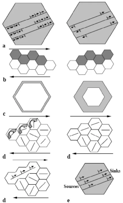
Figure 2.17 Sketches of different deformation mechanisms: (a) pile-up breakdown; (b) grain boundary sliding; (c) core and mantle; (d) grain coalescence; (e) sequential generation in grain boundary sources and annihilation in grain boundary sinks.
34
of UFG/NC metals and alloys. As shown in Fig.2.17, these models identify interrelationship between the deformation mechanisms active during grain refinement process and to determine their influence on the mechanical behavior.
The unique mechanical properties of UFG/NC materials are attributed to their unique deformation mechanisms, which, in many cases, are different from those in their CG counterparts. In summary, UFG/NC metals and alloys deform by mechanisms different from their CG counterparts. Deformation mechanisms in UFG/NC materials include slip of full dislocations and partial dislocations, deformation twinning, wide stacking faults, grain-boundary sliding and grain rotations. The activation and significance of each mechanism depend on intrinsic material properties such as stacking-fault energy and shear modulus, structural features such as grain size, and external factors such as applied stress and deformation temperature.
The following key points can be drawn from available molecular-dynamics (MD) simulations and experimental observations. Full dislocation slip is found active in grains as small as 10nm; however, its significance decreases with decreasing grain size. Emission of partial dislocations and deformation twinning become significant in nanostructured metals and alloys, even for those with high stacking-fault energy such as Al and Ni. There is a clear grain-size effect in the nucleation and growth of deformation twins. For metals and alloys with medium to high stacking-fault energy, deformation twins were observed in grains smaller than a certain value. Wide stacking faults were observed in nanostructured Al due to a grain-size effect. General planar fault-energy curves may be able to explain the stacking faults observed in nanostructured Ni but cannot reasonably predict the nucleation and growth of deformation twinning. Grain-boundary sliding and grain rotation may become significant deformation
35
mechanisms with decreasing grain size. [83]
2.3.5 Limitations of UFG/NC Metals
Strengthening at the cost of ductility is not uncommon, UFG/NC bulk materials indicate that they possess very high hardness and strength, 3~5times that of their CG counterpart, but their ductility, in particular uniform elongation in tension has been rather low and in the most cases nowhere close to that of the conventional metals and alloys. [84, 85] Both strength and ductility are the important mechanical properties of the materials for industrial applications. The UFG/NC materials have no capability to sustain a sufficient high rate of strain hardening and start necking soon after yielding, leading to a plunging tensile curve almost from the outset, which is a major shortcoming of UFG/NC materials.
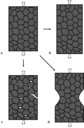
In general, the tensile ductility of a solid is controlled by a competition between plastic deformation and fracture processes as well as by the resistance to plastic flow localization (Fig.2.18). Most UFG/NC metals fail to exhibit homogeneous plastic deformation in tensile testing (Fig.2.18b) but instead they are characterized by low tensile ductility at room temperature because of two processes: (i) brittle crack nucleation and propagation instabilities (Fig.2.18c) and (ii) plastic strain instability in the form of a localization of plastic flow in shear bands and neck formation (Fig.2.18d). The former process dominates in UFG/NC metals having the finest grains with grain sizes, d, lower than a critical value of dc≈10~30nm depending on the material and
structure characteristics. Alternatively, plastic strain instability is the main factor causing low tensile ductility in NC metals with intermediate grain sizes up to 100 nm
36
and in UFG metals with grain sizes from 100 to 1000nm. [86]
Figure 2.18 Key evolution routes of a NC specimen under tensile load. (a) Initial state of the NC specimen. (b) Homogeneous plastic deformation of the specimen corresponding to its enhanced ductility. (c) Brittle fracture in the NC specimen occurs through crack nucleation and growth instabilities, typically involving the fast nucleation of nanoscale cracks, their convergence and/or growth along the grain boundaries. (d) The specimen shows plastic strain instability with necking. Routes (c) and (d) correspond to low tensile ductility. [86]
Crack nucleation instability (Fig.2.18c) means that plastic flow is suppressed in a solid so that the applied stress rapidly reaches a level close to the critical stress needed to initiate cracks near local stress concentrations. These concentrations may occur either
37
at fabrication-produced flaws or at defects generated due to the very limited local plastic deformation. The subsequent crack propagation is due to the suppression of conventional toughening mechanisms, such as lattice dislocation emission from crack tips that are needed to provide a resistance to crack growth. [87, 88]
Plastic strain instability in a solid under tensile deformation (Fig.2.18d) is controlled by its strain hardening rate. CG polycrystalline metals exhibit good tensile ductility due to high strain hardening associated with lattice dislocation storage in the grain interiors during plastic deformation. By contrast, UFG/NC materials often have low values of strain hardening rate so that they typically show plastic strain instability. The low ductility is caused by the low strain-hardening rate, which cause early-localized deformation in the form of necking. In general, two factors are responsible for the low or zero strain-hardening rate: (i) A high density of dislocations already exists in nanostructured materials processed by SPD and the density quickly reaches saturation upon further deformation. Once the saturation is reached, dislocations no longer accumulate inside the grains and strain-hardening rate becomes zero. (ii) In the grains with very small diameters e.g. <100 nm dislocations are emitted from a grain boundary segment and disappear into another grain boundary segment on the opposite side of the grain without accumulating inside the grain. The saturation density of dislocation is determined by a balance between the dislocation generation rate and the recovery rate, and this saturation density is expected to be higher at lower deformation temperature and higher strains. [89, 90]
Additionally, in practice, these techniques are often limited to the production of fairly small samples that may be useful for applications in fields such as electronic devices but are generally not appropriate for large-scale structural applications. Furthermore, the
38
finished products from these techniques invariably contain some degree of residual porosity and a low level of contamination, which is introduced during the fabrication procedure. These drawbacks could be an insurmountable hurdle in bringing UFG/CG bulk materials from laboratory to commercialization.
2.3.6 Approaches to Improve Ductility of UFG/NC Metals
As mentioned in Section 2.3.5, it is well-known that the inadequate ductility of UFG/NC materials is caused by plastic strain instability or crack nucleation instability which is achieved at the early stage of deformation. Therefore, a key to meeting the ductility challenge is to use stabilizing mechanisms to overcome the instabilities that threaten the tensile elongation of NS metals and alloys. The basic approaches adopted to enhance the tensile ductility of UFG and NC metals are outlined briefly in this section. [86, 91, 92]
(I) Bimodal (multi-modal) grain size distribution.
What turned out to be interesting is that one could do better than just a simple trade-off. When the bimodal structure was created on the nano-micro-scale, a large gain in work hardening and uniform strain was achieved, with only a (relatively) small loss of strength. The extra strain hardening ability may have something to do with the microstructural length scales involved, which are in this case close to the characteristic (or intrinsic) length scale of a material for strain-gradient plasticity to play a significant role. The storage of geometrically necessary dislocations required for compatible plastic strains may be pronounced for the unusually large strain gradient produced. Also
39
possibly contributing is the twinning activities triggered by stress concentrations in a highly non-uniform grain structure deforming at a high flow-stress level.
Bimodal bulk UFG/CG metals and alloys can be synthesized by: (i) Thermo-mechanical treatment involving severe plastic deformation, i.e., cold rolling or equal-channel angular pressing, followed by an appropriate thermal annealing under controlled conditions [93-95]; and (ii) Mechanical milling plus the consolidation of the milled powders mixed with certain volume fractions of the as-received CG powders [96-98]. Hono et al. [99-101] fabricated the bimodal bulk materials by mechanical milling at room temperature and spark plasma sintering (SPS). Lavernia et al. [102-104] have been developed cryomilling followed by various consolidation methods for manufacturing bimodal bulk metals and alloys. Bimodal bulk metals and alloys, wherein comprised of UFG/NC grains separated by CG regions, show balanced mechanical properties of enhanced yield and ultimate strength and reasonable ductility and toughness as compared to comparable conventional alloys and UFG/NC metals and alloys. As the volume fraction of coarse grains is increased, tensile ductility increase and strength decrease.
The tensile deformation and fracture mechanism of bimodal pure Al and Al-Mg alloys have been reported. An enhanced tensile elongation associated with the occurrence of a Lüders band was observed in the bimodal alloys. [105-107] In the bimodal pure Ni, it is also found that the large localized plastic strain within the coarse grains was observed during compression. The strain localization resulted in occurrence of debonding and cracks in the NC region or in the interface between CG and NC components. [108] A descriptive model for tensile deformation and fracture of bimodal UFG/CG metals, as shown in Fig.2.19. Firstly, the CG regions are elongated along the
40
extrusion direction in the as-extruded specimen (Fig.2.19a), and uniaxial tension is applied to the specimen along the extrusion direction. When the stress reaches the yield point of the CG material, plastic deformation occurs within these regions. Secondly, as the stress increases and reaches the yield point of UFG/NC material, voids initiate within UFG/NC regions and at UFG/CG interfaces and the CG bands undergo elongation, as shown in Fig.2.19b. Thirdly, as the tensile strain increases, cracks grow from the voids and extend transverse to the load axis. However, the cracks tend to be localized in UFG/NC regions between CG regions, as shown in Fig.2.19c. Cracks are effectively impeded by the CG stringers, which blunt and bridge the cracks, causing, in some cases, deflection and branching in CG regions and at UFG/CG interfaces. Finally, fracture ensues when cracks link and the CG regions can no longer sustain the load, as shown in Fig.2.19d. The ductile coarse grains in the UFG/NC matrix effectively impede propagation of microcracks, resulting in enhanced ductility and toughness while retaining high strength. [105-108]
Figure 2.19 Schematic of tensile deformation and fracture mechanism of bimodal UFG Al-Mg alloys under uniaxial tension along the extrusion direction: (a) as extruded, (b) void nucleation and growth, (c) crack growth, and (d) fracture. [107]
41
This approach has these advantages: (i) The idea is simple and easy to grasp, the grain structure can be induced through traditional thermo-mechanical means (e.g., through recrystallization and secondary recrystallization) in a bulk sample, and a bimodal grain size distribution can even be produced by consolidating a simple mixture of powders of pre-selected, different grain size. (ii) Also note that a functionally gradient material with a combination of good strength and ductility is beneficial for fatigue performance. There are also some inconveniences: the exact distributions of the grain size, grain shape, and spatial locations depend on many processing parameters and may be difficult to reproduce each time, and the overall material response hence becomes tricky to predict/model. The outcome properties therefore span a relatively wide range depending on the microstructural variations.
(II) Mixture of two or multiple phases with varying size scales and properties.
Figure 2.20 A scanning-electron microscope image of an in-situ composite formed via liquid casting of a titanium alloy. The matrix has a rod eutectic microstructure with eutectic spacing less than 100nm (see the TEM micrograph in the inset; the white scale bar represents 100nm). Embedded in the matrix are dendritic primary body-centered cubic titanium solid solution micrometers in size.[92]
42
A composite microstructure, wherein micrometer-sized ductile phase embedded in an ultra-strong (but brittle) eutectic product with UFG/NC spacing, was formed in-situ during casting (solidification) of the corresponding liquid titanium alloy. As perhaps expected, the microstructure shown in Fig.2.20 simultaneously provided impressive strength due to the large number of interfaces, a high strain hardening rate due to the dislocation accumulation in the micrometer-sized dendrites, and large plastic strains due to the large number of slip bands and profuse dislocation activities.
(III) Using nanoscale growth twins in lieu of the nanograins for strengthening.
It has been argued that a coherent twin boundary, while not much of a defect in terms of interface (grain boundary) energy, is very effective in blocking dislocations to require high stresses for slip transmission across this special grain boundary. Meanwhile, the twin boundaries do not encourage dynamic recovery as general high-angle grain boundaries or dislocation cells do. Dislocations accumulated in regions where the twin spacing is large, the thin twin ribbons were cut into pieces by dislocations tangles, and the twin boundaries had large numbers of dislocations and eventually became dislocation sources. In other words, the originally low defect content (with only coherent, low-energy twin boundaries) saved room for dislocation storage to further strengthen the material upon tensile straining.
(IV) Involving dispersions of nanoparticles and nano-precipitates.
Precipitation hardening is in fact the most potent strengthening method for many alloys. In UFG/NC grains, especially those on the larger side (on the order of 100nm), the hard precipitates also initiate, drag, and pin dislocations such that dynamic recovery
43
is reduced. Stress concentration is restrained during mechanical loading. The result is a significant dislocation storage required for compatible plastic strains, allowing a high strain-hardening rate that leads to larger uniform strains while elevating strength. Other dual phase microstructures, such as those in steels involving ultrafine martensites, are also advantageous in offering a good combination of strength and ductility.
(V) Using transformation-induced plasticity (TRIP) and twinning-induced plasticity (TWIP).
In tensile deformation, martensitic transformation was reported in UFG steel, at a rate similar to that in its CG counterpart so that the strain-hardening rate is also almost identical. Twinning-induced plasticity in some materials of low stacking fault energy is also likely. A very high density of extremely thin twins, often only two to several atomic layers thick, is observed in the tensile-tested UFG/NC cobalt sample. Some mechanical twinning and twin boundary migration may be ongoing to contribute to strength and strain hardening, although the majority of these observed twins must be growth twins formed during deposition of this metal of low stacking-fault energy.
(VI) Lowering of dynamic recovery at low-temperature (cryogenic temperatures) and/or dynamic strain rates.
In addition to tailoring the microstructure, changing deformation conditions, such as lowering dynamic recovery at low-temperature and dynamic strain rates, is known for CG face-centered cubic (FCC) metals and has been demonstrated to be applicable for UFG/NC FCC metals produced by SPD.
44
(VII) Improving strain rate hardening from the Hart’s instability criterion.
A material with strain rate sensitivity, m, of the order of unity could be superplastic. For FCC metals, going to the UFG/NC grain size does increase the strain rate sensitivity, especially at slow strain rates where grain boundary mechanisms help mediate deformation. Several reports also suggest that after many SPD rounds, copper, titanium, and aluminum alloys appear to show enhanced ductility. The reasons are yet to be fully clarified, but the refined grain sizes and the highly non-equilibrium grain boundary structures may be promoting grain boundary deformation mechanisms, which offer a relatively high m. As a result, uniform tensile deformation is stabilized to relatively large strains.
(VIII) Strive for truly flaw-free materials.
Porosity in consolidated UFG/NC materials may lower strength and help initiate shear localization; this may be partly responsible for the high propensity for shear banding in irradiated alloys or consolidated UFG/NC metals. Therefore, striving for truly flow-free materials is the paramount requirement for enhancing ductility.
2.4 Research Progress of Harmonic-structured Metals
Recently, ball milling has been widely exploited for the synthesis of various nanomaterials, nanograins, nanoalloy, nanocomposites and nano-quasicrystalline materials. The kinetics of mechanical milling or alloying depends on the energy transferred to the powder from the balls during milling. The energy transfer is governed by many parameters such as the type of mill, the powder supplied to drive the milling
![Figure 2.10 Production methods of UFG materials for respective grain size range. [40]](https://thumb-ap.123doks.com/thumbv2/123deta/6577336.1133547/31.892.182.706.646.979/figure-production-methods-ufg-materials-respective-grain-range.webp)