近畿大学学術情報リポジトリ
21
0
0
全文
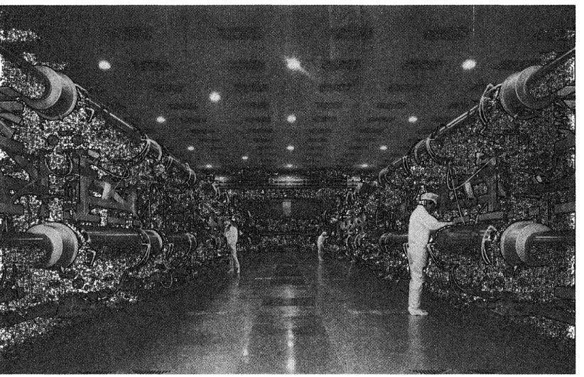
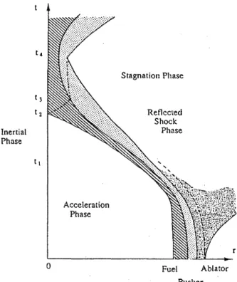
(2) 2. Energy drivers. The most important facility for ICF reactor is energy drivers, these should have a. high efficiency in a heavy duty operation. Advanced lasers and particle beams are the ca.nclicla.t.es. As for the ICF experiments, the N d glass lasers are well developed and most convenient for research purposes. In Table 1, the present status of research glass lasers is given. GEKKO XII glass laser at ILE Osaka, NOVA at LLNL and Omega. X-la.ser at. LLE Rochester are major installations for ICF experiments. In order to improve the int.eradion of laser light with plasmas, the wavelength of laser is converted to. the higher harmonics< 4 ) by using giant KDP crystals. The conversion efficiency is very high as much as 70 %. Grown crystals by the author a.re shown in Figure 1. To increase the uniformity of irradiation, a. random phasing bea.m< 5 ) was invented to eliminate the large scale spatial non-uniformity in the laser beam cased by the diffraction of the coherent light. The similar a.pproach is followed at LLE Rochester. Induced spatial incoherence by an echelon grating is also investigated to improve the bea.m quality a.t NRL. These innovations are very important for the direct. drive implosion to assure the uniform irradiation. Figure 2 shows the GEKKO XII laser system. Figure 3 is the laser irradiation system of twelve beams. This laser is ooe of the biggest laser in the world. According to a. scaling la.w for implosion, the necessary laser energy of the brea.keven is about 100 kJ at. blue. The proposed specification of upgrade of the GEKKO XII system is as followings. Pulse energy: Wavelength: Pulse width: Illumina.tion uniformity: Beam number: Beam diameter:. 3. The time evolution of the implosion dynamics of a. shell fuel with a. pusher can be eli viclecl into four phases. 1. Acceleration Phase (0 2. Inertial Phase (t 1. < t < t 1 ),. < t < t2),. 3. Reflected Shock Phase (t 2 4. Stagnation Phase. < t < t3 ). (t 3 < t < t 4 ). In the acceleration phase (1), the laser is absorbed to ablate the outer region of the target material and the rocket repulsion drives the pusher and fuel to accelerate inward. In the inertial phase (2), the fuel and pusher freely fall toward the target. center at. an a.ccelera.tecl velocity VA, the value of which is required to be 2 rv 3 x 10 7 cm/sec< 6 ). In this phase, the fuel and pusher tend to expa.nd due to their thermal pressure; therefore less preheat of these regions is necessary for the ideal ablative implosion. In the reflected shock phase (3), a void closure of shell triggers a. shock wave which propagates outwa.rd with heating the fuel by converting the direct.ed kinetic energy to the thermal energy. At the time when the shock wa.ve a.rrives at the contact. surface, the so-called stagnation phase ( 4) begins. If at t = t 3 the dynamical pressure (pu 2 ) of the pusher is la.rger than the static pressure (P) of the fuel, such discontinuity of the pressures leads t.o the generation of a. transmit.t.ed and reflected shock waves. Then, the fuel is further compressed and gains energy from the pusher through the adia.bat.ic compression in the st?gnation phase, if no nuxmg occurs.. 3.1. Ablation process of pellet. When one considers the ablation of a low-Z material, the electron energy transport plays an important role. Ablated plasmas expand into the vacuum with the velocity of sound C$ = (Pfp) 112 • Then, the so-called defla.gration form< 7 )(s) is introduced in the heated region. As the ablation region has almost constant pressure, which is almost equal to the ablation pressure PA, we can obtain an approximated energy conservation relation;. 100 kJ 0.35 p.m (blue) 2 ns (tailored) within 3% 24 beams 50 em. Implosion dynamics. (3.1) A scheme of the shell target implosion driven by the laser irradiation is schematically shown in Figure 4.. where Eab& is the absorbed laser energy and 7L the pulse width of the laser and C$TL is regarded as an. -22-.
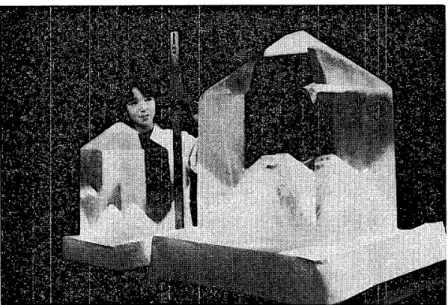
(3) Fig. 1. Giant KDP crystals cult.ivated by the author. Table 1 Nation Japan. Labora.t.ory Osaka.. U.S.A.. Lawrence Livermore National Laboratry Rochester N a.val Research Loboratry Levedev Physical Institute Phebus. Soviet. France. U.K.. Italy China. Limeil Atomic Energy Inst.it.ut.e Rutherford Appleton Laboratory Frascatt.i ENEA Shanghai Inst.i t. u t.e of Optics and Fine Mechanics. Glass laser systems in the world.. Device GEKKOIV GEKKO Mil GEKI<O XII NOVA. No. of beam 4 2 12 10. OMEGA PHAROS III. 24 3. DELFIN 2. 18x 12. Output energy KJ(wavelength llln}*** 1(1.0.5), 0 ..5(0.5.3), 0.0.5{0.26)* 2(1.05), 1(0.35) 26( 1.05), 17(0 ..53), 1.5(0.3.5) 120(1.05), 80{0 ..53), 70(0.35). 3(1.0.5), 2(0.35) 1.4( 1.05), 0.8(0.53). 12 8. 5(1.05) 10( 1. 05 )'"" 1(1.0.5) 20( 1.0.5). PHEBUS VULCAN. 2 12. 5( 1.05) 2(0.53). Liulu Jiqua.ng 12. 2 6 2. 0.1(1.0.5) 0. 18( 1.06) 2(1.05). DELFIN-2M OCTAL. 3~. * 1 bea.m. ** Under construction or designing *** Laser pulse 0.5"" 2 nsec -23-.
(4) 1:\:). *"". Layout of GEKKO XIT glass laser system of ILE, Osaka University (20 kJ, 40 TW in 12 beams).. Fig. 2. GEKKO XII glass laser system.
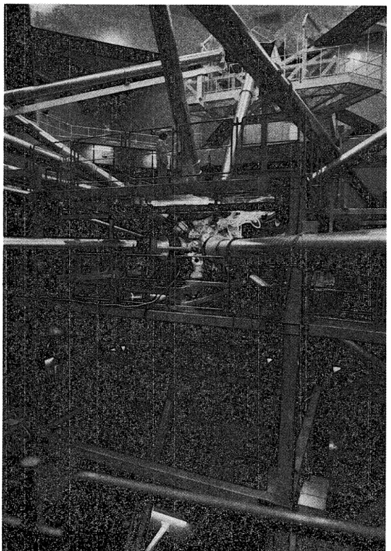
(5) Layout of GEK KO XII target irradiation system of ILE, Osaka University (Target room I for uniform irradiation).. Fig. 3. Laser irradiation syst.em -. 25-.
(6) '1:'. t4. "'. ~. Stagnation Phase. 10. ~. :::1. ~ ~ 0... t3. I':. Reflected Shock Phase. t2 Inertial Phase. .9 ~. :0. spherical targets uniform irradiation. <(. tl. -. 14. 10. Absorbed Intensity (WI em Acceleration Phase. 2. ). Fig. 5 Ablation pressure versus absorbed laser intensity. 0. Fuel. Ablator Pusher. Fig. 4 Schematic diagram of ablative driven implosion of a shell fuel target. vVhere P0 is a constant and A£ is the laser wavelength. In the model of stationary Chapma.nJougnet deflagration wave(s)( 9 ), the constant is shown to be. P0 t l 3 = 12Mbar effective width of the ablation region. In Eq. {3.1), we neglected the energy tra.nsferred to the accelerating shell. We obtain the ablation pressure in the form;. (3.2) where lab.• is the absorbed intensity of the laser flux h. It. is interesting to note t.ha.t. the photon pressure without no absorption is PP = 2h/c and this pressure is Cj/c. (sound speed/light. speed) times smaller than the pressure generated in the ablation process. It is clear from Eq. (3.2) that. for increasing the a.blation pressure, to keep the sound speed a.s low as possible is preferable. The generation of the fast ions should be avoided and the usage of the drivers depositing the energies in the higher density region is requested. If one assume the absorbed laser energy is carried by the electron heat flux lneveTe we have a relation I neVe lab .• which then provides,. 1:. (3.5). where Iabj is in the unit of 10 14 W /cm 2 and in pm unit in Eq. (3.4). In Figure 5, the tion pressures experimentally obtained are ted, where the solid lines show Eq: (3.4) Eq. (3.5) for A£ = 0.3.5 and 1.06 fJ. m. The ablation rate rh is also calculated . = 1n. 3.2. 113 \-4/3( 1.5 x 10 s 1abj, L g I em 2 sec ) .. A£ is ablaplotwith mass. (3.6). Rocket 1nodel for in1plosion. When the acceleration of the compressed region h~s the areal mass .M(t) and is accelerated to the velocity V(t) at time t, the equation of motion is reduced to the well-known Rocket equation;. dlf(t). ( ) A1t~=. p. (3. 7). A. t"V. I abj ]1/3. C ·• ex:. [ ncr I. (3.3). Inserting Eq. (3.3) into Eq. (3.2), we get. a scaling la.w of the a.hla.t.ion pressure;. In obtaining Eq. (3. 7), a plane geometry is assumed. Since M(t) = !110 - f~ 1i1dt, where !110 is the initial mass, Eq. (3. 7) is integrated with the assumption of constant. 1h and PA;. Afo ). V(t) = 2C .• ln ( AJ(t) (3.4) -. 26-. ,. ( .3. 8).
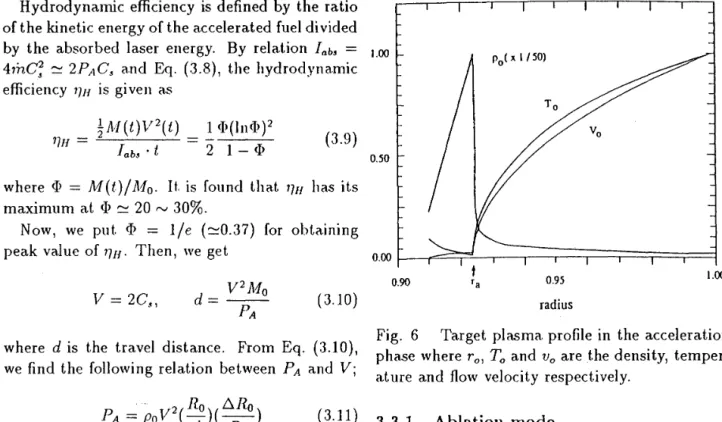
(7) Hydrodynamic efficiency is defined by the ratio of the kinetic energy of the accelerated fuel divided by the absorbed laser energy. By relation Iab!J = tm 47nC!J2 ~ 2PAC!J a.nd Eq. (3.8), the hydrodynamic efficiency 1]H is given a.s. p. 0. (. x 1/50). where <I> = M(t)/ Af0 . It. is found tha.t 7JH has its maximum at <I> ~ 20 rv 30%. Now, we put. <I> = 1/e (~0.37) for obtaining peak value of 7JH· Then, we get ( 3.10) where d is the travel distance. From Eq. (3.10), we find the following relation between PA and V; ·2 Ro 6.Ro PA = PoV ( - ) ( - ) d R0. ( 3.11). where Po and 6.R0 is the initial density and the thickness of a. target. shell respectively. Regarding Ro as an)nit.ial t.a.rget. radius, R 0 / 6.R 0 is the initial aspect. ra.t.io of a target. As an example, assuming a. target which consists of pure DT shell (Po = 0.2g/cm 2), the required ablation pressure for obtaining V = 3 x 10 7 cm/sec is calculated from · Eq. (3.11) to be 40 Mbar, where we set R0 /d = 2 and Ro/6.Ro = 10. From Eq. (3.11), it is found that the larger aspect fatio (R0 / 6.R0 ), the less ablation pressure is necessary to accelerate the target. It is noted that from Eqs. (3.4) and (3.5) the laser intensity required for PA = 40Mbar is Iab!J = 6 x 10 14 Apm (W /cm 2). Then a condition for the classical absorption h,\p.m2 < 2 x I0 14 W /cm2 which prevents the generation of the hot electrons re_quires the wavelength A£ < 0.33pm. This is one of the reasons why shorter wavelength lasers have been prepared for implosion experiments.. 3.3. Instability stagnation. of. ablation. and. Instability in implosion process is a crucial problem for the ICF. We have two cases of instability in the acceleration phase and in the deceleration phase. To prevent the growth of the instability is very important to pursue t.he implosion.· -. radius. Fig. 6 Target plasma profile in the acceleration phase where r 0 , To and V 0 are the density, temperature and flow velocity respectively.. 3.3.1. Ablation mode. It is important. to analyze the Rayleigh-Taylor instability of the dynamics in order to a.nswer whether the implosion scheme is realistic within the symmetry assumption. As shown in Figure 6, the steep density gra.dient is produced at r = 1'a against the inertial force working from the left to the right in the figure. Such situation is unstable to the Rayleigh-Taylor insta.bility, the growth rate of which is 'Y = y'kg, where k is the wa.ve number of a. perturbation and g is the gravitation which is equal to the acceleration of the ablation front. However, recent studies(IO)(ItKI 2)(IJ) reveal the fact that the growth rate is reduced due to the ablation and thermal conduction. As eigen-value analysis in the self-consistent structure as shown in Figure 6, gave the growth ra.te in a tractable form; 'Y. = a{k;- (Jk V0 ,. (3.12). where a = 0.9, f3 = 3 rv 4 are constants a.nd V0 is the flow velocity across the ablation front, which is equal to Vo = m/ Pa, where Pa is the maximum density at the ablation front. In Figure 7, the growth ra.te of Eq. (3.12) is given for CH-foil irradiated by 1.06 p,m (solid lines) and 0.25 {tm (dotted lines) laser lights. Equation (3. 12) suggests that. if we use a. driver and target materials which are able to enhance the ablative flow velocity V0 , we can reduce the 27-.
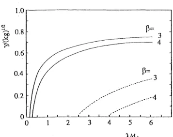
(8) 1.0. s. P=. bo 0.8 -. c~. where T 1,4 and p 1,4 are the temperature a.nd the density of the fuel at t = t 4 , while T1. 3 and p J, 3 are these data at t = t 3 . Here, it is useful to reduce Eq. (3.13) to the form;. 3 4. 0.6. v. P=. 0.4. 0. ----·4. 0. 2. 4. 3. 5. 6. A/di Fig. 7 Growth ra.te of Rayleigh-Taylor instability at ablation front "' normalized by its classical value -v'f"i as a. function of perturbation wavelength A divided by initial shell thickness di. growth of perturbations in longer wavelength and stabilize t.he instability with shorter wavelength. Therefore, the usage of shorter wavelength laser and low solid density (low Z) material is a good choice against the Rayleigh-Taylor instability.. 3.3.2. 3. Pp,3. ( 3.16). PJ,3. ----3 ... _ ......... -. 0.2. ,....,. . .t\.$ -. Stagnation mode. At t = t 3 in Figure 4, we introduce a stagnation parameter defined by. (3.13). where the relation 3/2P1,3 = 1/2p1,3 U?_ is used. from the energy conservation. This is a good approximation if the internal energy before the shock generation can be negligible. As seen from Eq. (3.15), when the fuel is accelerated up to Uc = 2 x 10 7 em/sec, the fuel temperature, which is about 500 eV at t 3 , will be 5 keV by stagnation heating, provided the pusher density is kept sufficiently high as satisfying Pp, 3 / p1,3 ~ 3. Then, the density at the maximum compression is about 5 times of the density at t 3 . In a stagnation dominant implosion mode, the fuel with lower density decelerates the pusher of higher density. The fuel-pusher contact surface tends to be unstable due to the Rayleigh-Taylor instability. This instability has been solved by an eigenvalue problem for linear perturba.tion in a spherical geometry< 14 ). A formula describing a tempora.l evolution of the perturbation amplitude €(t) is,. €(t) ex Rc(t)exp{jt[aAn(t)A(t)J11 2 dt},. (3.17). where Rc(t) is the radius of the contact surfa.ce, aA is the Atwood number, n = f/ Rc(t) is the ef-. where Pp, 3 , Uc, and P1, 3 are the density of the pusher, the velocity of the contact surface and the pressure of the fuel, respectively. If X 5 is la.rger than 1, the fuel is further compressed almost adiabatica.lly in the stagnation phase, until the time when the relation Uc = f~c ell is satisfied, where G'c is the deceleration of the contact surface due to the fuel pressure and this stagnation condition is to be; (3.14). fective wa.ve number of perttl]bation, and A is the acceleration of the contact surfa.ce at t. For the case of X 5 ~16, the temporal growths of the perturbation amplitudes for e = 10, 20, and 40 a.re plotted in Figure 8. The ordinate is the value of €(t)/Rc(t), while the abscissa is a normalized time where taking t = 0 at. the maximum compression. As shown in this figure, an explosive growth of the instability is seen in the stagnation phase, possibly inducing a fuel-pusher mixing.. where C 5 P is the sound speed of the pusher near the contact surface. Assuming the adiabatic process in the stagnation phase Eq. (3.14) provides the following relations;. In order to avoid the instability accompanied by the stagnation dynamics, the implosion scheme characterized by X 5 < 1 has been tested. For this purpose, it is required to ablate away the pusher until t = t 3 for decreasing Pp, 3 , to generate shockmultiplexing for increasing p 1,3 , and to accelerate the shell up to 10 8 cm/sec for heating the fuel up to 5 rv 10 keY by the reflected shock wave. Such. PJ,4. ~. X·2/3 PJ,3 &. (3.15). -28-.
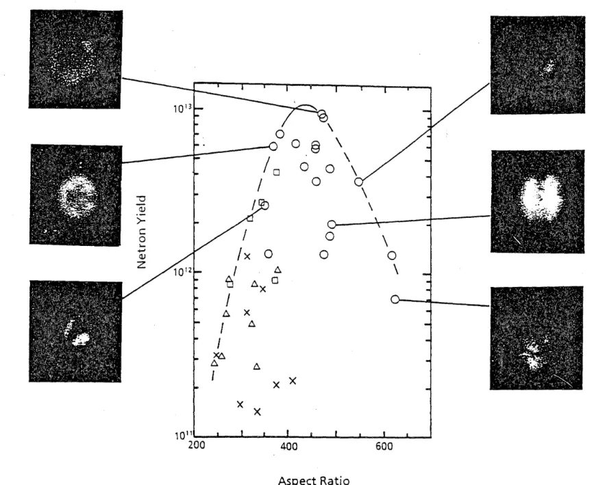
(9) l. Target.) and a shell fuel target t.o testify the fuel pellet. implosion. Let. us discuss a comparison of these two type of targets in the direct drive.. = 40. l = 20. 4.1 4.1.1. l = 10. -1. -2. -3. -4. 0. normalized time 4. 3. 2. f = Rc(t) !Rmin. Fig. 8 Tempora.l growth of perturbation amplitudes for € = 10, 20 and 40 tra.nsverse mode in stagnation solutions. Time is normalized. f = Rc(t)/ Rmin is convergen.ce rate where Rmin is the radius at. ma....ximum compression. implosion mode is named "Stagna.tion-free implosion". The world record of neutron yield is attained by t.his mode using "LHART" target..(lS)(lG). 4. Implosion experiments. LHART (Large High Aspect Ratio Target). A gas filled target LHART, we ca.n expect a. very high coupling efficiency as well as no mixing between the fuel a.nd the pusher. These a.re due to a. long acceleration distance of a pellet a.nd to a non stagnation condition at the maximum compression phase. In this scheme we could attain the neutron yield of 10 13 , energy gain 1/500 by using a. DT gas fuel in a. glass microballoon, 1 mm in diameter, 1 tLin of shell thickness, the aspect ratio 500 and the contained DT fuel pressure 6 at.m. The laser of this experiment. was 0.53 pm in t.he wavelength, 13 kJ of t.he energy and 1 ns of the pulse duration. In Figure 9, t.he simulation results are indicated wit.h data. of the neutron yield. This experimental result is well accorded with a simulation result of the ILESTAR ID code. The discrepancy is due to the 2 D instability. As well known, a. gas filled target is rather insensitive to the instability. However in this scheme, the DT fuel is shock heated to get too large entropy to be compressed to a higher density. The L HART concept will be useful for an ignitor.. 4.1.2. An irradiation scheme for implosion is specified by two categories: direct and indirect drive due to the configuration of fuel pellets. The former is to use the direct irradiation of laser beam on a target which dema.nds a. high uniform..ity of the energy deposition. A merit of this method is a high coupling efficiency of the beam to the target. The latter is to convert the laser light to X-ray in a double shell structure of a target which irradiates an inner fuel pellet. The uniformity of the compression is topologically expected. However the colipling of the laser light to plasma. is rather low. In both cases we have a. simila.r implosion dynamics of a fuel pellet in spite of the different irradiation schemes and target. configurations. We ha.ve ha.d excellent result.s(lS)(JG)(l 7 ) by using a. gas filled target. LHART (Large High Aspect. Ratio. Direct driven in1plosion. Shell fuel target. To_ get. t.he detail information of implosion experiment.s of the CD shell target were firstly performed. Uniformity of the illumination and also the pellet was carefully examined. Random phased beams were also used for a. better uniformity of the irradiation. The implosion velocity was measured by an x-ray streak camera. as shown in Fig. 10. The particle trajectories calculated by the HISHO code with the flux limit fa.ctor of f = 0.1 are also shown. As for the implosion dynamics, the experimental results se~m to coincide well with the simulation results. The maximum velocity of implosion reaches (8 rv 9) x 10 7 em/sec at the shell thickness of 4 rv 5 pm for 900 rv 1000 pm diameter pellet. The ion temperature is derived from the TOF neutron measmements. According to the increase of the. -29-.
(10) §. 0 0 ""0. I. L. 0 0. <lJ. >c. 0. 1.... +J. <lJ. w. 0. z. X'. /x. 0. I. 'CJ. I. A. I I. 0 0. A. X. \ 0. \. A 0. X. A. )(6,. A. I. A. X X X X I. I. I. I. 400. I. 600. Aspect Ratio Fig. 9 Aspect ratio dependence of neutron yield. The experimental curve indicates the ·optimum aspect ratio around 450..
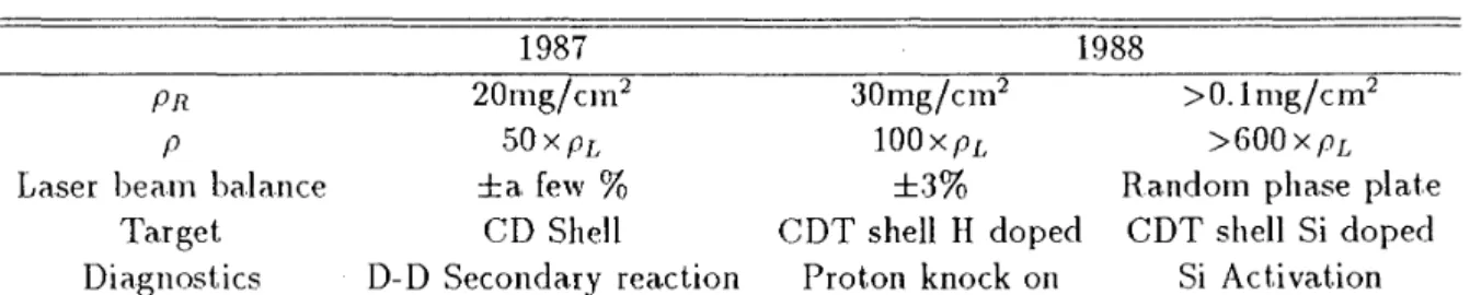
(11) 0. implosion velocity from 5 to 9 x 10 7 em/sec, ion temperature rises from 3 to 9 keV. During the last two years, we have performed the implosion experiments on various shell targets. These data are summarized in Table 2. In 1987, the CD plastic shell target gave us the areal R ( M I C) density of a compressed core pnR 20mg/cm 2 esti0 100 200 300 400 mated by the secondary fusion reaction measure-. 1''''1'' I'' I'' I ' , , , - - - - - - - - - ments of the D- D primary reaction( IS), where this value was almost the upper limit of the secondary reaction method in CD shells. The core density Pn is 50 times of the liquid density of D 2 fuel. In early 1988, we adopted CDT shell targets doping hydrogen atoms to use the proton knock on method. The track analysis of the knock on proton ga.ve the areal density PDTH R up to 30 mg/cm2 , which is the upper limit of the measurement.. In this case the core density was 100 times of the liquid fuel density. Finally we developed the 14 MeV neutron activation method to detect the areal density. The activation reaction 28 Si( n, p) 28 AI where the activation N is proportional to the neutron yield Yn and the fuel pR. The CDT shell targets (Si : 5.2 Wt% doped), whose diameter 500 p.m "" 700 ttm and wall thickness 5 p.m "" 15 pm were irradiated by the second harmonic light of the GEKKO XII glass laser, the pulse duration 1.5 "" 2 ns and the energy 10 kJ using the random phase plate. To get the a.bsolute a.ct.iva.t.ion N, we should get a collection factor of the a.ct.iva.t.ecl 28 Al. For this purpose we use the radioactive tracer 24 Na., 82 Br and 152 Eu for the collection calibration. The colFig. 10 X-ra.y streak image of hollow shell pel- lection reproducibility of a Nb collector was very let implosion. The x-ra.y pattern is represented high. The detail procedure of this method will by the mapping of isodensity traces. The particle be reported elsewhere. The measured PJuelR was 2 trajectories, which a.re obtained by simulation, are larger than 0.1 g/cm where we assumed a consta.nt content ratio of fuels. Figure 11 shows the superposed with same scales of time and space. relation between the pR and the shell thickness. II. II. I I. As we could easily measure the mass ablation rate by using multi-layer la.belled shell ta.rget< 19 >. This allows the fina.l compressed core density PJuel to be experimentally determined for a measured PJuelR value as follows:. PJuel =. ¥(PJuelR)3 (Af- D.Jvf)fuel. The experiment gives (A1 - !::J.A1)fuel = 0.5g. Then the minimum density achieved for Pfue/R = 31-.
(12) Table 2. 1987 20mg/cm 2. 30mg/cm. p. 50xpL. 100xpL. >600xpL. Laser beam balance Target Diagnostics. ±a. few% CD Shell D- D Secondary rea.ct.ion. ±3% CDT shell H doped Proton knock on. Random phase plate CDT shell Si eloped Si Activation. PR. 1 Q-1. Implosion data. of fuel compression. 1988. R phase. N. E 1 o-2 0. ........ Cl. Q). :I. ~. 1Q-3. a:. a.. 2. 4. 6. 8. Shell ThicKness. 10 12 <~m>. >0.lmg/cm2. O.lg/cm 2 is PJuel = 89g/cm3 . This is 600 hundred times of the liquid density. Figure 12 shows the implosion dynamics of the shell target measured by the X-ray framing camera and the streak one. This picture shows a very stable compression of the core. The core size indicates a good accordance to the experimental fuel density. The important. coefficients in laser implosion a.re the coupling efficiency 1Jc = (Eth/ EL) and hydrodynamic efficiency 1]Ji (Ek/17ab .• EL), where 1Jab$ and EL are absorption coefficient and the incidence laser energy, and Ek and Eth are the kinetic energy of the imploding shell and the thermal energy of the compressed core. The maximum hydrodynamic efficiency reaches 5 % at an optimum condition of pellet and laser parameters. The values of 1Jc/17ab$ coincide well with 1JH. This means the conversion efficiency from kinetic energy to thermal energy is very high.. ~:1 D simulation. R: random. 2. 14. 4.2. Fig. 11 Fuel a.real densi t.y > 0.1 g/cm2 has been a.chieved wi t.h hollow shell targets irradiated by random phased beam. ( 6 500 J.llll • 700 pm 0 900 pm in eli ameter). Indirect driven ·in'lplosion. Concerning an indirect drive concept, Cannonball target has two categories: forward cannon and rear cannon schemes< 2o)_ The former is to introduce the laser beams into a cavity through the holes on the outer shell which ads as an energy container as well as an X-ray radiator. The Fcannon is rather complicated for the irradiation of laser light. The latter is to be irradiated on the outer surface of a cavity shell by the laser which radiates the X-ray into the cavity through the shell itself. The R-cannon is much simpler to operate but the coupling is rather low. In both cases the cavity effects assures the spatial uniformity of radiation on the inner fuel pellet. The important issues of the Cannonball target are shown in Table 3. The X-ra.y conversion from. 32 -.
(13) Space (J.Lm) 0. 250. 500. x-ray framing images time resolution 88 psec x-ray region ,..., 1.5 ke V. 0. u. Q). -C/). c. Q). E. target. ~. diameter 500 J.Lm o.d. thickness ~ 8 ~m. 1 w. w. x-ray streak image. I. I 500 (Jlm). Fig. 12. Implosion dynam.ics of a shell fuel target recorded by the X-ray framing and streak camera...
(14) 1. well as the X-ray conversion efficiency at the outer shell< 21 ).. 10~~~~-.~~~~. -:$. 0. Rear. ::5. ). ~r. 0. Front. 5. > ...... Target: Au hemisphere. :s. 800J.Im.,/0.3)Jm. ·u; c:. -c Q). -1. 3kJ/0.8ns d/R:-6. -F. -2. .. ·---- R! Experiment. T<I) 10 E. i=. -F!. Simulation. ------ R1 -3. 10. L...~__.__.__.__._~..__...._.. 0. 50 Wavelength. Ignition and burn. A high pellet gain of about Q = 10 2 is required for realizing a. reactor of ICF. This is because a. driver efficiency 1}d and coupling efficiency 1Jc is limited to be 1]d1Jc < < 1 and the core gain G = { thermonuclear energy)/(imploded DT fuel energy) of order 10 3 is necessary for a net gain. Assume that D-T plasmas heated uniformly up to 10 ke V, the core gain G of the thermonuclear reaction is calculated to be. Laser: 3w. 10. .....co ....C) .....<I) c:. 5.1. 1. <I). Concept of ICF reactor. 100. <A>. Fig. 13 The x-ra.y emission on the front side and the rea.r side from the gold half shell target. The experimental a.nd simulation results are given.. the laser energy is rather high a.nd the spectrum range is suitable for ablation if we select. proper shell metals. -We have investigated the X-ra.y spectrum which is generated in a. gold semisphere shell, whose diameter 800 pm and thickness 0.3 pm irradiated by the 6 beams of GEKKO XII laser light in 3 kJ of the third harmonics in 0.8 nsec pulse duration. In Fig. 13 the experimental results are compared with th~ computer simulation data due to the non local thermoequilibrium fluid code. ILESTA 1D. The X-ray ernissions on the front side and the rear side of the gold half shell are shown. One ca.n see the difference in t.he emission spectrum composed of N band (800 eV} and 0-band (250 eV) between the front. and the rear side. Figure 14 shows the computed implosion dia.gra.m of a. R-Ca.nnonba.ll target. whose outer gold shell is 600 pm in diameter, 0.5 pm thick a.nd the fuel GMB shell is 242 pm in diameter, 2.08 Jtm thick with coating of the 9.0 p.m CF by the irradiation of energy 7.2 kJ, pulse duration 0.84 ns in blue light. One ca.n see the X-ra.y emission from the gold shell fairly implodes the inner fuel shell. The key issues of the Ca.nnonba.ll target are the suppression of the hand X-ray component, the confinement of X-ray radiation in a. cavity a.nd the absorption of the X-ray on the fuel shell as -. where f B is the burn fraction. The core gain G ca.nnot get the value 103 in a uniform heating. The high gain concept requires a.n ignitor scheme by which the compressed DT plasma have an inner spark ignition with the temperature 5 rv 10 ke V and an outer main fuel region with the internal energy as low as possible. Then, the alpha. particles produced in the spa.rk region heat the main fuel to trigger the nuclear reaction. The ICF research is requested to demonstrate a.t first the ignition of the fuel and next to attain the high pellet gain.. 5.1.1. Ignition condition. The ignition condition is given from the energy balance of the D- T plasmas \vhich are assumed to be -tmiformly heated and compressed. The energy e(]uation to the plasmas with the assumption of Te = Ti =Tis p. ciT. 3 - - = -P\lu + \1 Ke \lT- Ln 1nj dt. + Ho. (.5.1). where the fist term of the right pa.rt gives the expansion loss LE, the second one is thermal conduction loss Lc, the third one represents radiation cooling L n, a.ncl the forth one is the a.lpha.-pa.rticle heating H 0 • If the DT plasmas have the radius R, density p, and temperature T, each cooling term of Eq. (5.1) is roughly evaluated to be. (5.2) 34-.
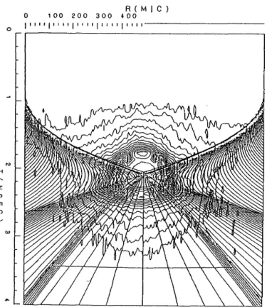
(15) 0. w Cf). z. 0. 1. 00. 200. 300. 400. R(M!C). Fig. 14 The computed implosion dynamics of a. R cannonball target, 600 J..lm diameter of outer gold shell and 242 llm diameter of fuel GMB coated 9 J..lm CF. The blue laser of 7.2 kJ a.nd 0.84 ns pulse is irradiated.. -. 35-.
(16) Table 3. Key issues of pellet implosion by laser produced X-ray radiation in Cannonball target.. ( 1) X- ray Convection Efficiency Spectrum Emission time (2) Cavity Effect Laser absorption in cavity Reemission and radiation tra.pping Energy loss to the expanding plasma and to the ca.vity wall (3) Pellet Implosion Absorption Transport A blat.ion and acceleration Preheating Symmetry. >60% few 100eV. 70% trapping of radiation ?. multi-component coating ionization burn through high ablation non-electronic good. Lc = - \l f{e \JT 712 1 T 10 19 - - k 2InA R. (5.3). Aop 2 T 112 = 2. 77 x 10 23 p 2 T~/ 2. (.5.4). ~ ]{ T 7' 2 0 .. LR. c:::::. (5.6). 1. 1?2. = 87. .. X. where each laser formula is in cgs unit. and Tk is the temperature in keV unit. In Eq. (5.2), we evaluated "Vu = -1j pdpjdt as r ex: R- 3 and dRjdt c::::: 2C$, where C$ is the sound velocity. The alpha-particle heating term is given in the form;. = 8.07. X. 40. l0 (av) DT fap. 2. (5.5). where Ea = 3.521\.feV, fa < 1 is the energy deposition fraction of alpha-pa.rticle, and (av)DT is a function of only the temperature. The fraction fa is roughly given as fa ~ 1 - ( 1 - pRj p,\a) 2 for R < >-a and fa c::::: 1 for R 2:: >-a, where >-a is the stopping range of the a.lpha-pa.rticle. N ot.e that p,\a slightly depends upon the density< 23 ) and approximately equal to p,\a c::::: 0.04Tk(gjcm2 ) in the region of interest.. Then, we define the ignition condition by the fact that the right part of Eq. (5.1) blances each other ; namely, Le Lc + LR = Ha. Multiplying R 2 to Eq. ( .5.1 ), we obtain the relation between pR and Tk·. +. This relation is shown in Figure 15 with thick solid line. For the reference, another conditions obtained for Lc + LR = Ha(CR), Le = Ha(E), Lc = Ha(C), and LR = Ha(R) are plotted. As seen in this figure, when the expansion loss is dominant, pR rv 0.4gjcm 2 at 10 keV is the ignition condition. A number of simulations on the fusion burn have been performed< 23 ) with the uniformly compressed DT fuel. As well-known, a simple estimate< 24 ) of the fusion burn fraction without taking into account. the self-heating is, pR. fB = pR + /3\Ti)'. where f3(T,) = 8m,C$j(av}DT is a function of only 7i. It is noted that for pR < < f3(Ti), f B ·e::::: pRj f3(Tc) and the burn fraction increases in proportionally to pR. The ignition point is given by the pR value at which the f B departs to increase from the linear line in Figure 16.. 5.1.2. Neces..,ary energy for ignition. The DT plasma with the areal density pR and the temperature T1 ( = Te) have the internal energy UnT; UnT = 10.6 x 10. 8. 7 x 10 18 T; 12. + 1. 72. x 1023 Ti,P pR. (5.7). 9. (pj~$)2(pR) 3 Tk(Joule). (5.8). where p$ is the solid density and pR in gjcm2 unit. In Figure 17, three lines indicate (pR) 3 Tk = 0.1, 36 -.
(17) 10°r------------------------------. 10. T. = 20 keY. 1 ,..-... N. 8. -. Ill. (.). 4-<. 10. -3. O J). '-../. ~. a. -4. 10. 0.1. • 0.1 mg • 0.3 mg 1.0 mg X 10.0 mg. A. -6. /. 10. 0.01 10. 10 -3. 100. 10-1. 10. pR (g I cm 2). Ti (keY). Fig. 15 Ignition conditions eva.lua.ted from simple energy balances. -. Fig. 16 Bum fraction of DT core numerically evaluated as a function of core pR with initial temperature 3, 6, 10 and 20 keV at various fuel mass.. 37-. I.
(18) c ,........ ..... 4. 1.0. s. 3. u ..._ .!:9. p:::. Q._. 2. 1.0 0.5 0.1 0.1. L---~~~~~~----~~~~~. 1. 10. 100. 0. Ti (keY). Fig. 17 Ignition cha.racteristics of DT fuel using the ignition point given by Figure 16. Curve A corresponds t.o 10 % deviation from Eq, ( 5. 7) and curve B for 100% deviation. Curve Cis due to the simple energy balance. The relations of (pR) 3 T = 0.1, 0.5 and 1.0 are plotted with thin solid lines.. 2. 3. 10. (a). 3. {pP) errT k = 0.5. ~/Po(%). 0.5, and 1.0, respectively. For coupling efficiency 10%, the driver energy of 10 kjoule is enough for · ign~tion defined by the curve A. Therefore, if a spherically symmetric implosion wa.s done, UDT = 1 kjoule is a.rf ignition condition at. pf P~ = 10 3 for (pR) 3 Tk = 0.1. However, the implosion symmetry is a key issue and the estimation of UDT including a symmetry effect is essential. The curve B in Figure 17 shows the 10 times severe ignition condition estimated from Figure 16. The dotted curve is estimated by a. simple energy balance.. 5. ~~--~~~n---o-,-TOTTin. 4. 3. 2. If the core radius R is deformed with a perturbation with amplitude (due to the non uniformity of laser irradiation or other effects; then, the effective pR contributing t.o the fuel burn will be given, (pR)eJJ = p(R- () ~ pR(1- o{/ Ro). ~~~~~~U---L-~~~~. 10. 0. ~~~~uw~~~~~~~~. 10. 2. 3. 10. (b). (5.9). where 0:' = R 0 / R rv (A 0 f3pf P~ ) 113 and R 0 and Ao a.re the initial radius and the aspect ratio. Inserting pR of Eq. ( 5.9) in Eq. (5.8), for the cases of (pR)~JJTk = 0.1 and 0.5 at A 0 = 10, we get. Figure 18 (a.) and (b), respectively. In Figure 16, if we set UDT = 10 kjoule and pj p$ rv 103 , the required uniformities a.re 3.5% for (pR)~JJTk = 0.1 a.nd 1.5% for (pR)~JJTk = 0.5 respectively. Therefore, for a substantial ignition the uniformity of (/ R 0 equal to 2 ,....., 3 % is required for a. 100 kjoule driver with the coupling efficiency 10 %. · -. Fig. 18 Core uniformity a.nd energy requirements for ignition fuel. Parameters a.re the internal energy UDT·. 38-.
(19) For the case of the indirect drive, the coupling efficiency is less than 1 %, however the nonuniformity of the core is much better than that of the direct drive. The required driver energy is expected to be a few Mjoule. The choice of the direct drive and the indirect drive is a controversial issue for ICF resea.rch. In the Figure 19, simulation results< 22 ) are shown for two cases of a. gaseous target and a. cryogenic shell target, where one-dimensional hydrodynamic calculations were carried out considering an instability. According to the above theoretical prospect., we will be able to obtain the fusion energy larger tha.n the laser energy on a target (breakeven), by using a 100 kJ laser system and the high gain by a few MJ laser. Nuclea.r characteristics of an ICF reactor are much different from those in other types of fusion schemes such as magnetic confinement. fusion system. Unique features of neut.ronics in an ICF reactor a.re summarized below:. 'U QJ. >c. 0. ..... +-'. ::J QJ. z. ,. , ,,. ,0. , ,0. 1. Neutron a.re generated in a very small volume (< 100 p m) and neutron source is regarded as a point source. This fad means tha.t. neutron tra.rlsport. analysis is to be carried out. in a spherical geometry in on-dimensional discussions.. 2. Duration time of neutron generation is very short ( < 100 psec) and time-dependent. studies must. be carried out. 3. Intensive neutrons are moderated not only in a blanket la.yer, but. also in a dense plasma core, because the fuel plasma. areal density (pR) is increased to a large value of 1 "' 10 g/cm 2 , which is almost. equivalent to a fewem-thick shield of wa.t.er. The third feature is very important and unique, because the neutron energy spectrum is soft.ened, resulting in modification of the nuclear features in a. blanket. such as tritium breeding ratio (TBR = number.of bred tritium/per DT fusion) and wall damage due to the neutrons. Three-dimensional a.nalysis on neutronics in a. rea.ctor cavity concept. of SENRI-I< 25 ) enabled us to proceed to the advanced and systematic design. More than 30 years operation ca.n be expected in the design.. 100K. 1M. 10M. Fig. 19 Laser energy dependance of neutron yield. The soliid line is for cryogenic fuel, while the dotted line is for gas fuel. The effective neutron yield evaluated by considering an instability driven by 3% absorption nonuniformity of f. = 10 mode is also plotted (Yiv ).. -39-.
(20) Great. efforts have been concentrated to the ICF rea.ct.or design and engineering studies, because the recent. progress in a.n ICF plasma. enabled us to prospect the feasibility of the ICF scheme to be realized a.s a. useful and effect.i ve fusion rea.ct.or.. (6] Bodner, S. E.,(1981), J. Fusion energy, 1, 221.. 6. (9] Ahlborn, B., Key, M. H., and Bell, A. H.,. (1982), Phys. Fluids, 25, 541.. Summary. Implosion results ha.ve been greatly progressed with the improved irradiation to the advance fuel pellet and with sophisticated diagnostics of implosion a.nd compressed core. The data base on the ICF has been accumulated for the brea.keven experiment. The 600 hundred times liquid density and pRof 0.1 g/cm2 have been demonstrated by shell pellet t.a.rget.s. The reactor concept of ICF is also investigated to give us an excellent prospect in the near future.. Acknowledgements The author wishes to express his sincere appreciation to his colleges at Institute of Laser Engineering, Osaka. University and at Institute for Laser Technology who worked with him for the theoretical and experimental researches. Thanks are also due to the members of Research Institute for Science a.nd Technology, Kinki University whose support. made this report. The author also acknowledge the invaria.ble help of his secretary, Junko Horimoto, preparing the ma.nuscript... (7] Bobin, J. L., (1971), Phys. Fluids, 14, 2341. (8] Ta.ka.be, et a.l., (1978), J. Phys. Jpn., 45, 2001.. (10] Ta.ka.be, H., Mont.iert.h, L., and Morse, R. L., ( 1983), Phys. Fluids, 26, 2299. (11] Emery, M. H., Gardner, J. H., and Boris, J. P., (1982), App/. Phys. Lett., 41, 808. (12] Emery, M. H., Gardner, J.P., and Bodner, S. E., ( 1986), Phys. Rev. Lett., 57, 703. [13] McCrory, R. L., Mont.ierth, L., Morse, R. L., and Verdon, C. P., (1981), Phys. Rev. Lett., 46, 336. (14] Hattori, F., Takabe, H., and Mima., K., (1986), Phys. Fluids, 29, 1719. (15) Yamanaka., C. Nakai, S., (1986) Nature, 319, 757 (1986). (16] Yama.na.ka., C., (1987) in : Plasm·a Phys. and Control Nucl. Fusion Res. (IAEA, Vienna., 1986), 3, 33. [17) Yama.na.ka., C., (1988 b), XVI Inter. Conf. on Quant. Elect. Plenary Presentation, Tokyo. (18] Miyana.ga, N., (1986), Rev. Sci. Inst. 57, 8, 1713.. References (1] Yamanaka., C., (1988), Journal of Inst. electronics, Information, Commun. Engineers, Ja.pa.n 71, 690. [2] Yamanaka, c., et al. (1987), Nuclear Fusion, Supplement 3, 33. [3) Mima., K. et al. (1988), A.P.S. meeting on Plasnw Physics, Invited paper.. [19] Ya.ma.na.ka., C. (1985), Nuclear Fusion, Supplement, 3, 3. [20] Tanaka, K., {1988), Japan-US Seminar on Genera.t.ing, application of Hot Dense Laser Plasma, Hawaii. [21) Mochizuki, T., et al., (1987), Nuclear Fusion, Supplement 3, 25. (22] Ta.ka.be, H. et a.l., ( 1988), 12th Inter. Conf. on. [4) Ya.mana.ka., C., (1988 a.), Proceeding of Sem-. inar on Short Wavelength Lasers and Their Applications 1, Springer. [5] Kato, Y., et al. (1984) Physics Rev. Lett., 53, 1057.. Plasma and Controlled Nuclear Fusion Synopsis, 95. [23) Fraley, G. S., Linnerberg, E. J., Mason, R. J., and Morse, R. L., (1974), Phys. Fluids, 17, 474.. -40-.
(21) [24] Bodner, S. E., (1981), J. Fusion Energy, 1, 221.. -. 41-.
(22)
図
+7

関連したドキュメント
Standard domino tableaux have already been considered by many authors [33], [6], [34], [8], [1], but, to the best of our knowledge, the expression of the
The present paper shows how to assess the contribution made by negative selection relative to other tolerisation mechanisms by deducing the impact of negative selection on the T
¿Es posible aún hablar de ellos y saber que lo que hablamos tiene algún sentido? ¿O por el contrario, deben ser considerados inconce- bibles? Para mí, no dudo en considerarlos
(i) Cuando el efecto del tratamiento es bajo (OR = 0,90), el modelo M1 presenta el porcentaje mayor de valores significativos (ef-peto = 41 %, ef-clásico = 33 %), a diferencia de
An application is given to a mixed problem of general parbolic partial differential equations with fractional order.. Keywords and phrases: Fractional integral and
In order to measure the efficiency rather than inefficiency, and to make some interesting interpretations of efficiency across comparable firms, it is recommended to investigate
Using the multi-scale convergence method, we derive a homogenization result whose limit problem is defined on a fixed domain and is of the same type as the problem with
Greenberg and G.Stevens, p-adic L-functions and p-adic periods of modular forms, Invent.. Greenberg and G.Stevens, On the conjecture of Mazur, Tate and
