Ignition Experiments by Nanosecond
Repetitively Pulsed Discharges in Intense
Turbulence for Super Lean Burn at Engine
Condition
著者
Kodai Uesugi, Youhi Morii, Taichi Mukoyama,
Takuya Tezuka, Susumu Hasegawa, Hisashi
Nakamura, Hidemasa Takana, Kaoru Maruta,
Takeshi Yokomori, Norimasa Iida
journal or
publication title
Society of Automotive Engineers technical
paper series
volume
Technical Paper
year
2019-12-19
URL
http://hdl.handle.net/10097/00130840
doi: 10.4271/2019-01-2160
JSAE 20199308
SAE 2019-YY-YYYY
Ignition Experiments by Nanosecond Repetitively
Pulsed Discharges in Intense Turbulence
for Super-lean Burn at Engine Condition
Kodai Uesugi, Youhi Morii, Taichi Mukoyama, Takuya Tezuka,
Susumu Hasegawa, Hisashi Nakamura, Hidemasa Takana
Institute of Fluid Science, Tohoku University
Kaoru Maruta
Institute of Fluid Science, Tohoku University / ICE Lab. Far Eastern Federal UniversityTakeshi Yokomori, Norimasa Iida
Keio UniversityCopyright © 2019 SAE Japan and Copyright © 2019 SAE International
ABSTRACT
Ignition by Nanosecond Repetitively Pulsed Discharges (NRPD) at EXponential Increase of Minimum Ignition Energy (MIE-EXI) region under super lean SI engine conditions was studied. Fundamental experiments were conducted with a turbulent ignition test chamber with twin counter-rotating fans. The MIE-EXI region by arc discharge appeared over 6500 rpm of fan speed. In the MIE-EXI region (7000 rpm), successful ignition was achieved by establishing coupled ignition kernels with NRPD at 15 kHz although ignition was unsuccessful at 1 kHz. Results show that ignition by NRPD has potential advantages for lean burn applications. Preliminary engine test results with NRPD were also demonstrated.
INTRODUCTION
Internal Combustion (IC) engine is said to be in use for around 75 % of automobiles even at 2040 [1]. Thus, it is necessary to continue research and development of highly efficient IC engines. To realize efficient Spark Ignition (SI) engines with more than 50% thermal efficiency, study of cross-ministerial Strategic Innovation Promotion Program (SIP) for IC engines (2014-2019) has been conducted in Japan [2]. This project is aiming for drastic increase of IC engine thermal efficiency by large compression ratio and super-lean burn concept, based on the higher specific heat ratio and low temperature combustion which contributes to lower heat loss.
One of the challenging issues in super-lean burn is low laminar burning velocity. To overcome this, a long-stroke single-cylinder engine with intense tumble flow was employed in the SIP engine project [3] as suggested by earlier study by Nakata et al. [4]. A port
adapter was installed the SIP engine to enhance tumble flow [3]. At super lean conditions, however, significant increase of required ignition energy which controls lean limit operation was observed [4]. Under such conditions, unacceptable increase of Coefficient Of Variation (COV) of Indicated Mean Effective Pressure (IMEP) was observed.
It was pointed out in two same reports [5,6] that significant increase of required ignition energy at super lean burn engine could be regarded as “minimum ignition energy transition (MIE Transition) phenomena” which was first discovered by Shy et al. [7,8] by the fundamental combustion chamber experiments. Shy et al. [7,8] reported that the increase of minimum ignition energy in intense turbulence occurred regardless of fuel concentration at intense turbulence where Peclet number is larger than the critical value [5,6]. They termed such condition as EXponential Increase of Minimum Ignition Energy (MIE-EXI) region.
To realize successful ignition at MIE-EXI region in super lean burn engines, high-power ignition systems with ten ignition coils were introduced in the SIP IC engine project. This ignition system enables successful enhancement of lean limit of SIP engines [3] and contributed to increase its thermal efficiency. Nevertheless, alternative ignition method with higher energy efficiency is expected.
A fundamental study of ignition to deflagration transition process in laminar flow condition was conducted analytically and computationally [9]. It is then followed by experimental confirmation [10]. In [9], a concept of critical flame radius which enables successful flame propagation from ignition kernel was first proposed. It was also clarified that the critical flame radius depends essentially on ignition energy
and Lewis number. Since Lewis number of practical gasoline and air mixture for automotive engines could not be manipulated, another solution is a formation of larger ignition kernel than the critical flame radius by introducing Nanosecond Repetitively Pulsed Discharges (NRPD). Such strategy was confirmed to be effective up to the atmospheric pressure level for gas turbine application [11]. Experimental study with NRPD showed that the flame propagation could be attained in methane and air mixture with bulk flow when repetitive ignition by NRPD successfully produced coupled ignition kernels [11]. NRPD is one of the non-thermal plasma technology which potentially has two major advantages. One is smaller heat loss to the electrodes due to lower gas temperature compared to arc discharge. Another is its chemical reaction enhancement potential [12]. From the above, further improvement of thermal efficiency for SI engines could be expected by introducing NRPD. In the present study, we demonstrate preliminary results of ignition experiments at intense turbulent condition with a fundamental constant volume chamber with twin counter-rotating fans to generate isotropic turbulence. Two kinds of the ignition systems, a high energy arc ignitor identical to SIP engine system and a NRPD ignitor were employed. In addition to the chamber experiments, SIP engine tests with NRPD ignitor was also conducted. Our objective is to clarify the ignition capability of NRPD through the observation of the ignition kernel in intense turbulence using arc discharge and NRPD for lean burn engine conditions.
EXPERIMENTAL METHOD
IGNITION SYSTEMS
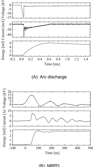
Two types of ignition systems, a SIP high-power ignition system equipped with multiple ignition coils [3] and a pulse power unit (TE-HPS-15K-A(C), MPC1110S-15KLP) were used to generate arc discharge and NRPD, respectively. In the case of arc discharge, the ignition energy was controlled by changing the number of ignition coils and charging time to the coils. The number of coils was from 1 to 10 and the charging time is up to 4 ms. In the case of NRPD, the discharge energy was controlled by changing discharging frequency and output voltage. Discharging frequency was from 1 kHz to 15 kHz and output voltage was up to 15 kV. The ignition energy is estimated by the measurements of voltage and current histories using a high voltage probe (P6015A) and a current probe (TCPA300, TCP312A). The ignition energy was calculated by a time integration of voltage and current. Figure 1 shows examples of time histories of voltage, current and the ignition energy in the cases of the discharging time of 0.6 ms for arc discharge (A) and those of 50 ns for NRPD (B). The duration by arc discharge was controlled in the range of 0.5 – 2.5 ms. Discharge duration of NRPD is much shorter than that of arc discharge. -15 -10-5 0 -40 -20 0 -0.2 0.0 0.2 0.4 0.6 0.8 1.0 1.2 1.4 0 2 4 6 Vo ltage [kV] Curren t [mA] Ene rgy [m J] Time [ms] (A): Arc discharge
0 5 10 15 20 -5 0 5 10 -1000 0 100 200 300 400 500 1 2 3 Vo ltag e [ kV] Cu rre nt [ A ] Ene rgy [mJ] Time [ns] (B): NRPD
Figure 1 Examples of time histories of voltage, current and ignition energy by arc discharge (A) and NRPD (B). TURBULENT IGNITION TEST CHAMBER
Schematic diagram of the experimental apparatus is shown in Figure 2. The apparatus consists of the gas supply system, observation system, ignition system and turbulent ignition test chamber with twin counter-rotating fans which can generate isotropic turbulence. The chamber design was the same as [13]. The rotational speed of the fans was controlled from 1500 to 12000 rpm which correspond to the turbulent intensity u’ from 1.16 to 9.24 m/s from the reference data [14,15]. Methane/air mixture at equivalence ratio (air excess ratio λ = 1.67) and the pressure p = 101.3 kPa was supplied by partial pressure method. Dried air compressed by an air compressor was used. The purity of methane was 99.999%. The ignition kernel is observed through the quartz windows and Schlieren images were recorded by using a high speed camera (PHOTRON FASTCAM SA3, Mini AX). Twin tip electrodes made of stainless steel were installed at the center of the combustion chamber. The gap and thickness of the electrodes were 2.5 and 2.0 mm. Two types of ignition systems, arc discharge and NRPD were employed.
Figure 2 Schematic diagram of the experimental apparatus and electrodes.
SIP ENGINE
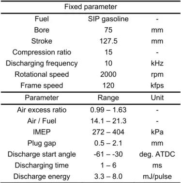
Schematic diagram of the SIP engine laboratory equipped with pulse power unit which can generate NRPD and experimental conditions are shown in Figure 3 and Table 1, respectively. Experimental data such as in-cylinder pressure and the crank angle was recorded by using the combustion analysis software (DS3000). The intense tumble flow port [2] was installed at the intake port to increase turbulent intensity for higher turbulent burning velocity. Ignition behavior of the combustion chamber was observed by using the borescope and high speed camera (PHANTOM v2011). SIP gasoline which has 99.8 Research Octane Number and 42.28 MJ/kg lower heating value was used as fuel. The three types of plug gaps were 0.5 mm, 0.9 mm and 2.1 mm. Discharge start timing was set at extremely advanced compared to conventional engine because of the increase of burning velocity accompanied by low pressure. The rotational speed of the engine was fixed at 2000 rpm. In the engine tests, the same NRPD system with the present fundamental experiment was employed.
Figure 3 Schematic diagram of the SIP engine laboratory.
Table 1 Experimental conditions of SIP engine tests. Fixed parameter
Fuel SIP gasoline -
Bore 75 mm Stroke 127.5 mm Compression ratio 15 - Discharging frequency 10 kHz Rotational speed 2000 rpm Frame speed 120 kfps
Parameter Range Unit
Air excess ratio 0.99 – 1.63 - Air / Fuel 14.1 – 21.3 - IMEP 272 – 404 kPa Plug gap 0.5 – 2.1 mm Discharge start angle -61 – -30 deg. ATDC
Discharging time 1 – 6 ms Discharge energy 3.3 – 8.0 mJ/pulse
RESULTS AND DISCUSSION
IGNITION EXPERIMENTS WITH TURBULENT IGNITION TEST CHAMBER
At first, ignition experiments by NRPD were conducted at rotational speed of fans 6000 rpm (u’ = 4.62 m/s [14,15]). The time evolution of the Schlieren images (each size: 21 × 19 mm2) of the ignition process by
NRPD at discharging frequency 1 kHz (a) and 2 kHz (b) are shown in Figure 4. The discharge energy of (a) is 3.52 mJ/pulse and (b) is 3.00 mJ/pulse. The inset number of each image at the top left indicates the number of discharges. Each elapsed time is shown at the bottom of the images. In the case of 1 kHz (a), the ignition kernel which formed between the electrodes was flown away and flame propagation was not achieved eventually. In the case of 2 kHz (b), successful formation of the ignition kernel was achieved in spite of the lower discharge energy per pulse compared to (a). Results implied that not only the increase of the discharge energy per pulse, but also the increase of discharging frequency is important for the successful ignition.
High power ignition system or Pulse power unit
Motor
Fan Perforated plate
High voltage probe
Current probe Oscilloscope Vacuum pump CH4 Air High speed camera Lens Light source Back pressure
Baratron pressure gauge
Knife edge
Electrodes
Control room
Pulse power unit
Voltage probe Current probe Oscilloscope High speed camera with bore scope SIP engine Plug Trigger
SIP engine room
PC
(a): “no go” at 3.52 mJ/pulse and 1 kHz.
(b): “go” at 3.00 mJ/pulse and 2 kHz.
Figure 4 Time evolution of Schlieren images (21 × 19 mm2) at 6000 rpm (u’ = 4.62 m/s).
Next, Ignition experiments by NRPD were conducted at 7000 rpm (u’ = 5.39 m/s [14,15]). The time evolution of Schlieren images (each size: 38 × 42 mm2) of the
ignition process by NRPD at 1 kHz (a) and 15 kHz (b) are shown in Figure 5. The discharge energy and total pulses of (a) are 11.3 mJ/pulse, 250 pulses and (b) are 10.2 mJ/pulse, 200 pulses. In the case of 1 kHz, each ignition kernel was decoupled and finally flame propagation was not achieved due to low discharging frequency as well as Figure 4 (a). In the case of 15 kHz, however, successful formation of the ignition kernel was achieved even under intense turbulence. From these results, it is considered that successful ignition can be achieved because ignition kernels were coupled by high discharging frequency.
(a): “no go” at 11.3 mJ/pulse, total 250 pulses and 1 kHz.
(b) : “go” at 10.2 mJ/pulse, total 200 pulses and 15 kHz.
Figure 5 Time evolution of Schlieren images (38 × 42 mm2) at 7000 rpm (u’ = 5.39 m/s).
Based on the ignition experiments by arc discharge and by NRPD at 15 kHz in intense turbulence, go and no-go results were shown in Figure 6. Black open circles show “go” by arc discharge, black crosses show “no go” by arc discharge and red circles show “go” by NRPD at 15 kHz. From the results of arc discharges in Figure 6, the required ignition energy for successful ignition rapidly increases with the increase of the rotational speed at a certain condition. The MIE transition occurred at a higher rotational speed than in [16]. In our apparatus, the exponential increase of the ignition energy appeared around 6500 rpm (u’ = 5.01 m/s [14,15]). From the figure, successful ignition could be attained by NRPD in intense turbulence which implied that NRPD exhibited potential advantages in intense turbulence compared to arc discharge.
Figure 6 Results of ignition experiments by arc discharge and NRPD under turbulent conditions. SIP ENGINE TESTS
SIP engine tests were conducted by NRPD. The results of COV by arc discharge [2] and NRPD in the present study are shown in Figure 7. Three types of plug gaps were used. Closed black circles, closed red squares and closed blue triangles indicated plug gaps of 0.5 mm, 0.9 mm and 2.1 mm in the case of NRPD (arc discharge case : d = 0.9 mm). From Figure 7, successful ignition by NRPD was attained at λ = 1.63 (equivalence ratio and d = 0.9 mm. The COV results by NRPD revealed that similar tendency with the results by arc discharge. CO and NOx emissions by NRPD showed that similar tendencies with the arc discharge case although figures are not shown here. It is implied that NRPD could not show its full potentials from the observation of unsuccessful discharge which will be shown in subsequent figures (Figures 8 – 10).
0 1000 2000 3000 4000 5000 6000 7000 8000 0.00 0.77 1.54 2.31 3.08 3.85 4.62 5.39 6.16 0 20 40 60 80 100 120 140 160 180 0 20 40 60 80 100 120 140 160 180 Discha rge e nergy b y NRPD [mJ/pulse ] go arc no go arc NRPD 15 kHz u' [m/s] Ignition ene rgy by a rc disc harge [mJ] Rotational Speed [rpm]
0 5 10 15 20 0.8 1.0 1.2 1.4 1.6 1.8 2.0 0 5 10 15 20 Arc discharge, d = 0.9 mm w/o port adapter, coil 1 w/o port adapter, coil 10 w/ port adapter, coil 10
NRPD, w/ port adapter, d = 0.5 mm d = 0.9 mm d = 2.1 mm
COV [%]
Air excess ratio [-]
Figure 7 Comparison of COV results by arc discharge in ref. [2] and by NRPD in the present study.
Figure 8 shows direct images taken inside of the combustion chamber using bore scope. Unsuccessful discharge was observed from these images.
Figure 8 Direct images of the combustion chamber after discharge captured through bore scope.
The in-cylinder pressure as a function of crank angle by NRPD is shown in Figure 9. Symbols in the figure indicate the timings of discharge stop. Closed red circles represent plug gap at 0.5 mm and motoring condition and closed blue triangles represent plug gap at 2.1 mm and firing condition. In fact, discharge stopped halfway because of the increasing in-cylinder pressure. From Figure 9, it is seen that discharge stopped around from 1000 to 1600 kPa.
To estimate the limit condition of the discharge, the assumption of one-dimensional reduced electric field (E/n [Td]) expressed by Equation (1) was considered.
Successful discharge is expected if the value of the reduced electric field exceeds certain threshold value. The estimation of reduced electric field as a function of crank angle by NRPD was attempted as shown in Figure 10. All the data points were estimated based on firing experimental data. Regarding the voltages, experimental data were used for estimating black circles and blue crosses. Black circles indicate “discharge” and blue crosses indicate “no discharge”. The estimation of required voltages were plotted by closed red triangles for 30 kV and closed green squares for 20 kV. The value of reduced electric field is 77.2 Td when discharge stopped. From Figure 9, the estimated values of 30 kV case seems to be sufficient for successful discharge although 20 kV is not. These results imply that the NRPD have some additional
potential for enhancing the engine lean limit if pulse power unit has sufficient voltage.
The number of successful discharges are 33 as shown in Figure 10. The total ignition energy integrated by the discharge energy per pulse (about 4.5 mJ/pulse) until the discharge stop point is 149.4 mJ.
Figure 9 The in-cylinder pressure as a function of crank angle. -60 -50 -40 -30 -20 -10 0 50 100 150 200 250 300 350 400 Firing, = 1.54 d = 2.1 mm Exp. discharge Exp. no discharge Estimated 30 kV Estimated 20 kV Reduc ed el ect ric fie ld [Td]
Crank angle [deg. ATDC]
Figure 10 The estimation of reduced electric field as a function of crank angle.
CONCLUSIONS
Experimental study of ignition under intense turbulent conditions was conducted by arc discharge and Nanosecond Repetitively Pulsed Discharges (NRPD) in a turbulent ignition test chamber. The following results were obtained:
1. Not only the increase of the discharge energy per pulse, but also the increase of discharging frequency is identified to be important for the successful ignition.
2. Successful ignition was achieved by NRPD in intense turbulence where arc discharge could not be successful.
3. NRPD exhibited potential advantages in intense turbulence compared to arc discharge.
SIP engine experiments by NRPD were also conducted. The following results were obtained:
4. Successful ignition was attained at λ = 1.63 and d = 0.9 mm. -50 -40 -30 -20 -10 0 10 20 0 1000 2000 3000 4000 5000 0.5 mm, motoring 2.1 mm, firing Pr es sure [kPa]
Crank angle [deg. ATDC] Unsuccessful breakdown Successful breakdown
ா
ൌ
ಳ்
ௗ
…(1)5. The COV results by NRPD revealed that similar tendency with the previous results by arc discharge.
ACKNOWLEDGMENTS
This work was partially supported by Council for Science, Technology and Innovation (CSTI), Cross-ministerial Strategic Innovation Promotion Program (SIP), Innovative Combustion Technology (JST). The authors express sincere appreciation to Prof. S.S. Shy of National Central Univ., Taiwan for construction of fundamental constant volume chamber and insightful discussion on the MIE transition.
REFERENCES
1. IEA, Energy Technology Perspectives 2012, av ailable at https://www.iea.org/publications/freepu blications/publication/ETP2012_free.pdf , 2018. 2. JST, SIP Innovative Combustion, available at
http://www.jst.go.jp/sip/k01.html, 2018 (in Japanese).
3. T. Yokomori, M. Matsuda, N. Iida, Y. Urata, N. Yokoo and K. Nakata, “Research on super lean burn concept for gasoline engines with high thermal efficiency,” JSAE, 20165267, pp. 1413– 1418, 2016.
4. K. Nakata, S. Nogawa, D. Takahashi, Y. Yoshihara, A. Kumagai, and T. Suzuki, "Engine technologies for achieving 45% thermal efficiency of S.I. engine," SAE Int. J. Engines 9(1), pp. 179-192, 2016.
5. K. Maruta and H. Nakamura, “Super lean-burn in SI engine and fundamental combustion studies,” Journal of the Combustion Society of Japan, 58(183), pp. 9-19, 2016 (in Japanese).
6. K. Maruta and H. Nakamura, “On the transition from ignition to flame propagation in super lean burn SI engine –Engine combustion research and fundamental combustion research–,”JSAE, vol. 72, No. 4, pp. 10-17, 2018 (in Japanese).
7. C. C. Huang, S. S. Shy, C. C. Liu, and Y. Y. Yan, “A transition on minimum ignition energy for lean turbulent methane combustion in flamelet and distributed regimes,” vol. 31, no. x, pp. 1401–1409, 2007.
8. L. J. Jiang, S. S. Shy, M. T. Nguyen, S. Y. Huang, and D. W. Yu, “Spark ignition probability and minimum ignition energy transition of the lean iso-octane / air mixture in premixed turbulent combustion,” Combust. Flame, vol. 187, pp. 87–95, 2018.
9. Z. Chen, M. P. Burke, and Y. Ju, “On the critical flame radius and minimum ignition energy for spherical flame initiation,” Proc. Combust. Inst., vol. 33, no. 1, pp. 1219–1226, 2011.
10. M. Nakahara, F. Abe, and K. Tokunaga, “Fundamental burning velocities of meso-scale
propagating spherical flames with H 2 , CH 4 and C 3 H 8 mixtures,” Proc. Combust. Inst., vol. 34, no. 1, pp. 703–710, 2013.
11. J. K. Lefkowitz and T. Ombrello, “An exploration of inter-pulse coupling in nanosecond pulsed high frequency discharge ignition,” Combust. Flame, vol. 180, pp. 136–147, 2017.
12. W. Sun, S. H. Won, T. Ombrello, C. Carter, and Y. Ju, “Direct ignition and S-curve transition by in situ nano-second pulsed discharge in methane/oxygen/helium counterflow flame,” Proc.
Combust. Inst., vol. 34, no. 1, pp. 847–855, 2013.
13. S. S. Shy and M. L. Lin, “A new cruciform burner and its turbulence measurements for premixed turbulent combustion study,” vol. 20, pp. 105–114, 2000.
14. T. S. Yang and S. S. Shy, “Two-way interaction between solid particles and homogeneous air turbulence: particle settling rate and turbulence modification measurements,” vol. 526, pp. 171– 216, 2005.
15. M. Peng, S. S. Shy, Y. Shiu, and C. Liu, “High pressure ignition kernel development and minimum ignition energy measurements in different regimes of premixed turbulent combustion,” Combust. Flame, vol. 160, no. 9, pp. 1755–1766, 2013.
16. S. S. Shy, C. C. Liu, and W. T. Shih, “Ignition transition in turbulent premixed combustion,”
Combust. Flame, vol. 157, no. 2, pp. 341–350,
2010.
CONTACT
Kodai Uesugi
E-mail: [email protected]
DEFINITIONS, ACRONYMS, ABBREVIATIONS
: Equivalence ratio -
λ: Air excess ratio -
E: Electric field V/m
n: Electron number density m-3 kB: Boltzmann constant J/K
T: Burned gas temperature K
V: Voltage V
P: Pressure kPa

![Figure 7 Comparison of COV results by arc discharge in ref. [2] and by NRPD in the present study](https://thumb-ap.123doks.com/thumbv2/123deta/5921063.1051218/6.892.93.395.61.287/figure-comparison-cov-results-discharge-nrpd-present-study.webp)
