• 検索結果がありません。

September, 2014 Masaki Haibara Tokyo Metropolitan University Studies on oxygen reduction reaction in ionic liquids

N/A
N/A
Protected

Academic year: 2021

シェア "September, 2014 Masaki Haibara Tokyo Metropolitan University Studies on oxygen reduction reaction in ionic liquids"

Copied!
107
0
0

読み込み中.... (全文を見る)

全文

(1)

Studies on oxygen reduction reaction in ionic liquids

September, 2014

Masaki Haibara

Tokyo Metropolitan University

(2)
(3)

General introduction・・・・・・・・・・・・・・・・・・・・・・・・・・・・・・・・・・・・・・・・・・・・・・・・・・・1

・Background of this study

・Application of Ionic liquids for PEFC electrolyte ・Outline of this work

Chapter 1・・・・・・・・・・・・・・・・・・・・・・・・・・・・・・・・・・・・・・・・・・・・・・・・・・・・・・・・・・・19

Characterization of five protic ionic liquids having different fluoroalkyl chain

length of anion

1-1. Introduction 1-2. Experimental

1-3. Results and discussion 1-4. Conclusions

Chapter 2・・・・・・・・・・・・・・・・・・・・・・・・・・・・・・・・・・・・・・・・・・・・・・・・・・・・・・・・・・・49

(4)

2-1. Introduction 2-2. Experimental

2-3. Results and discussion 2-4. Conclusions

Chapter 3・・・・・・・・・・・・・・・・・・・・・・・・・・・・・・・・・・・・・・・・・・・・・・・・・・・・・・・・・・・75

Analysis of oxygen reduction reaction in ionic liquids at middle temperature using

flow cell

3-1. Introduction 3-2. Experimental

3-3. Results and discussion 3-4. Conclusions

General conclusions・・・・・・・・・・・・・・・・・・・・・・・・・・・・・・・・・・・・・・・・・・・・・・・・・・・99

Acknowledgments・・・・・・・・・・・・・・・・・・・・・・・・・・・・・・・・・・・・・・・・・・・・・・・・・・・103

(5)

General introduction

Background of this study

Recently, from the problem such as abnormal weather around the country due to global warming and energy shortage due to depletion of fossil fuels, clean energy conversion devices are required. Thus, fuel cells have been attracted for clean energy conversion device [1-5]. In fuel cells, chemical energy of fuel is directly converted to electric energy without thermal energy and mechanical energy [6-9]. The fuel cells have higher energy conversion efficiency than the thermal power generation systems as shown in Fig. 1. The fuel cells have been investigated since 19th, and various kinds of fuel cells have been developed. As listed in Table 1.

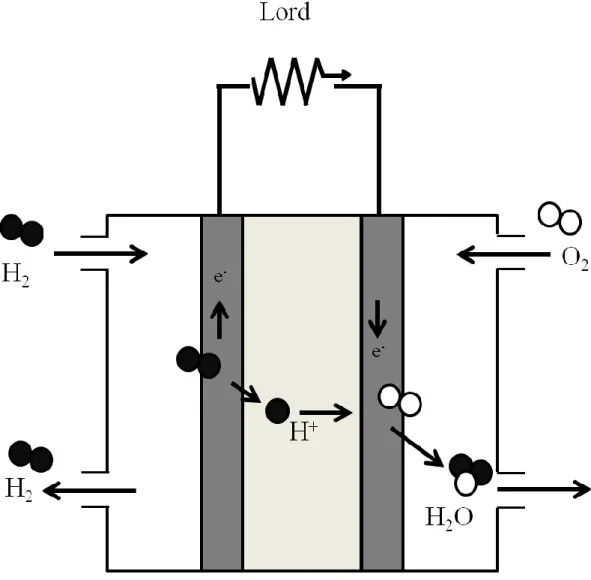
Polymer electrolyte fuel cell (PEFC) is compact, and the operating temperature

is low. Therefore, PEFCs have been studied as a portable power source for various kinds

of mobile tools. The PEFC was depicted by stacking of Membrane Electrode

Assemblies (MEA). MEA consists of proton conductive polymer electrolyte membrane

and two catalytic electrodes for anode and cathode. In general, anode and cathode are

(6)

fabricated on polymer electrolyte membranes by hot-press method as shown in Fig. 2.

PEFC is operated by following reactions [10, 11]:

Anode : H

2

→ H

+

+ e

-

E˚ = 0 V vs SHE Cathode : 1 / 2 O

2

+ 2H

+

+ 2e

-

→ H

2

O E˚ = 1.23 V vs SHE Total: H

2

+ 1 / 2 O

2

→ H

2

O E˚ = 1.23 V vs SHE

For practical application of PEFC, there are several problems. Firstly, Pt used for PEFC catalyst is expensive and not abundant. The annual production of Pt is about 180 tons, and the total reserves of Pt is about 36,000 tons. According to the New Energy and Industrial Technology Development Organization ( NEDO ) report, the amount of Pt used in vehicles having fuel cell with the power of 80kW, 150kW and 250kW is 32 g, 62g and 150g, respectively. At present, in this usage of Pt the vehicles, the number of fuel cell vehicles should be equal or less than 10 % of the total number of vehicles.

Hence, it is necessary to reduce the amount of Pt or to search for new materials in order

to replace the Pt catalyst. In the former, many researchers have reported ways to reduce

the amount of Pt by the fabrication of Pt nanoparticles [12-15] and core shell structures

[16-21]. In the latter, oxide-based non precious metals catalysts [22-28] and carbon

(7)

alloy catalysts [29-33] have been reported as Pt catalyst alternative materials.

Secondly, there are the problems of PEFC electrolyte membrane. For the application to vehicles, it is desirable to use the PEFC at high temperature to obtain a large current. As the electrolytes for PEFC, fluoropolymer electrolytes such as Nafion®

have been used because of high proton conductivity and good chemical stability. However, those electrolyte membranes have to be used under humidified conditions to maintain high proton conductivity. Therefore, the PEFC system needs humidifying apparatus and becomes large. As a result, PEFC operation is still limited up to 80 °C although the catalyst activity is strongly reduced by CO poisoning at low temperatures. Thus, new electrolyte materials, which can be used without humidification at temperatures higher than 100 °C, are needed [34-38].

These problems have to be solved for the development of PEFCs. By referring a load map reported by NEDO, the parametric requirements for electrolyte membranes using in PEFCs are follows:

For the PEFC vehicles

Vehicle efficiency: > 60 % Lower Heating Value (LHV)

Long stability: 5000 h (at operation condition)

(8)

Operation temperatures : - 30 °C ~ 90 – 100 °C Pt and noble metals amount : ≧ 0.1 g kW

-1

Stack cost : 10 thousand yen kW

-1

For the stationary PEFCs

Conversion efficiency : > 33 % Higher Heating Value (HHV) Long stability : 60000 h (at operation condition)

Operation temperature : 80 ~ 90 °C

System cost : 5 ~ 7 million yen

(9)

Fig. 1 Conversion efficiency of various power generation systems.

(10)

Table 1 Type of fuel cells

(11)

Fig. 2 Schematic diagram of MEA for PEFC

(12)

Application of ionic liquids for PEFC electrolyte

Ionic liquids, which are molten salts at room temperature as shown in Fig. 3, have attracted considerable attention as PEFC electrolyte materials at intermediate temperatures (higher than 100 °C) under non-humidified conditions because of their notable special characteristics such as non-volatility, non-flammability, high thermal stability and electrochemical stability.

Type of ionic liquid can be classified by the combination of acid and base. The first is Lewis acid ionic liquid, which is synthesized from the transfer of electrons between acid and base. It is indicated that ionic liquids were chloro-aluminate salts. The choloro-aluminate salts are unstable in air because these are hydrolyzed easily by water.

The second is Brönsted acid ionic liquid, which is synthesized by the transport of protons between acid and base. In general, Brönsted acid ionic liquids are called protic ionic liquids (PILs). Brönsted acid ionic liquids are prepared by neutralization reaction. This procedure is a very simple and equimolar mixing provides salts. This has no problem of contamination by undesirable by-product salts. Therefore, Brönsted acid ionic liquids are promising for applications in a wide range such as fuel cell electrolyte [39].

In order to utilize PILs to fuel cells, the characteristics of PILs as electrolytes have

been extensively studied. Watanabe et al. has studied thermal properties, physicochemical

(13)

properties and electrochemical properties of PILs that were synthetized from various kinds of ammonium based cations or imidazolium based cation and various strong acid or super acid anions [40-45]. They reported that N,N-diethylemethyleammonium, trifluoromethanesulfonate ([dema][TfO]) was appropriate for ORR [44, 45]. In addition, it has been reported that the PEFC applied with [dema][TfO] showed an output density of more than 100 mW cm

-2

[46]. Hagiwara et al. has developed fluorohydrogenate anion ([FHF

-

]) based PILs having layered crystal structures. Both cation and anion transports in those PILs are so fast and the proton transport is supported by [FHF

-

] anion rather than by cation. Therefore, [FHF

-

] based PILs are preferable as fuel cell electrolyte materials.

Actually, it has been reported that the single cell test using [FHF

-

] based PILs shows the

power density of 200 mW cm

-2

at 80 °C. It has been also reported that the cell operation at

130 °C under non-humidified condition [47-50]. In addition to those researches, studies on

electrolyte membranes impregnated with PILs have been recently focused [51-55].

(14)

Fig. 3 The picture on photograph of ionic liquid

(15)

Outline of this work

As described in above literatures, PILs for the application of PEFC electrolyte are ideal material. However, in literatures of [dema][TfO] electrolyte membrane, it was reported that the fuel cell performance decreased above 100 °C . [57]. In literatures of [FHF

-

] based PILs electrolyte membrane, it was suggested that [FHF

-

] anion reacted with water generated by PEFC operation at high temperature and decomposed to HF. This is similar to the decomposition mechanism of BF

4

and PF

6

based PILs [58]. Thus, for application of ionic liquids for PEFC electrolyte under non-humidification above 100 °C, there are several problems. In addition, optimal design guide of ionic liquids have not been obtained for application of PEFC electrolyte.

So far, we have focused on the ORR in PILs which were synthetized by combination of anions having different fluoroalkyl chain lengths and [dema] cation. In previous study, the ORR in those PILs on Pt electrode has been analyzed by in-situ infrared spectroscopy (in-situ FT-IR). From this measurement, it was found that the adsorption and desorption behavior of the anion in PILs strongly affects the ORR activity.

This result shows that the ionic liquid comprising an anion weakly absorbed on Pt surface, which can be easily released by applying a potential, is appropriate for the ORR [59].

This work focused on fluoroalkyl chain length of anion in PILs. Several PILs

(16)

with different fluoroalkyl chain length in anion were synthesized and evaluated physicochemical properties and electrochemical properties.

In Chapter 1, a series of PILs were synthesized from [dema] and three kinds of fluoroalkylsulfonic acids having different chain lengths (H-SO

3

(CF

2

)nF, n = 1~3) or two kinds of bis(fluoroalkylsulfonil)imide acids having different chain lengths (H-NS

2

O

4

(C

2

F

4

)nF

2

, n = 1~2), and investigated the effect of fluoroalkyl chain length.

In Chapter 2, among the PILs synthesized in Chapter 1, three fluoroalkylsulfonic acids having different chain lengths (H-SO

3

(CF

2

)nF, n = 1~3) were focused and investigated the effect of fluoroalkyl chain length on the solubility and diffusion coefficient of O

2

in the [dema]-based PILs to discuss the appropriate design of PILs for intermediate temperature fuel cells.

In Chapter 3, to investigate the ORR in PILs at high temperature in detail, a

channel flow double electrode cell was prepared and ORR at Ni or Au in [dema]-based

PILs at 120°C was investigated.

(17)

References

[1] R. Helmolt, U. Eberle, J. Power Sources, 165 (2007) 833-843.

[2] S. G. Chalk, J. F. Miller, J. Power Sources, 159 (2006) 73-80.

[3] M. yano, A. Tomita, M. Sano, T. Hibino, Solid State Ionics, 177 (2007) 3351-3359.

[4] P. Costamagna, S. Srinivasan, J. Power Sources, 102 (2001) 242-252.

[5] P. Costamagna, S. Srinivasan, J. Power Sources, 102 (2001) 253-269.

[6] M. Broussely, G. Archdale, J. Power Sources, 136 (2004) 386-394.

[7] E. Karden, S. Ploumen, B. Fricke, T. Miller, K. Snyder, J. Power Sources, 168 (2007) 2-11.

[8] T. E. Springer, T. A. Zawodzinski, S. Gottesfeld, J. Electrochem. Sor., 138 (8) (1991) 2334-2342.

[9] C. M. Miesse, W. S. Jung, K. J. Jeong, J. K. Lee, J. Lee, J. Han, S. P. Yoon, S. W.

Nam, T. H. Lim, S. A. Hong, J. Power Sources, 162 (2006) 532-540.

[10] E. Antolini, Energy Environ. Sci., 2 (2009) 915-931.

[11] N. V. Long, Y. Yang, C. M. Thi, N. V. Minh, Y. Cao, M. Nogami, Nano. Energy, 2 (2013) 636-676.

[12] M. Watanabe, H. Sei, P, Stonehart, J. Electroanalytical Chemistry and interfacial

Electrochemistry 261 (1989) 375-387.

(18)

[13] M.Laurent-Brocq, N. Job, D. Eskenazi, J. Pireaux, Applied Catalysis B : Environmental 147 (2014) 453-463.

[14] J. Molina, J. Fernández, A. I. del Río. J. Bonastre, F. Cases, Materials characterization 89 (2014) 56-68.

[15] Y. Kazuki, T. Tetsuya, T. Tsukasa, K. Susumu. ECS Trans., 33(7) (2010) 127-133.

[16] M. Lopez-Haro, L. Dubau, L. Guétaz, P.Bayle-Guillemaud, M. Chatenet, J. André, N. Caqué, E, Rossinot, Applied Catalysis B : Environmental 152-153 (2014) 300-308.

[17] J. Zhao, A. Manthiram, Applied Catalysis B : Environmental 101 (2011) 660-668.

[18] G. Zhang, Z. Shao, W. Lu, F. Xie, H. Xiao, X. Qin, B. Yi, Applied Catalysis B : Environmental 132-133 (2013) 183-194.

[19] D. A. Cantane, F. E. R. Oliveira, S. F. Santos, F. H. B. Lima, Applied Catalysis B : Environmental 136-137 (2013) 351-360.

[20] B. Geboes, I. Mintsouli, B. Wouters, J. Georgieva, A. Kakaroglou, S. Sotiropoulos, E. Balova, S. Armyanov, A. Hubin, T. Breugelmans Applied Catalysis B : Environmental 150-151 (2014) 249-256.

[21] I. Mintsouli, J. Georgieva, S. Armyanov, E. Valova, G. Avdeev, A. Hubin, O.

Steenhaut, J. Dille, D. Tsiplakides, S. Balomenou, S. Sotiropoulos, Applied Catalysis

B : Environmental 136-137 (2013) 160-167.

(19)

[22] K. D. Nam, A. Ishihara, K. Matsuzawa, S. Mitsushima, K. Ota, M. Matsumoto, H.

Imai, Electrochim. Acta, 55 (2010) 7290-7297.

[23] A. Ishihara, K. Lee, S. Doi, S. Mitsushima, N. Kamiya, M. Hara, K. Domen, K.

Fukuda, K. Ota, Electrochim. and Solid-State Lett. 8 (2005) A201-A203.

[24] Y. Shibata, A. Ishihara, S. Mitsushima, N. Kamiya, K. Ota, Electrochim. and Solid-State Lett., 10 (2007) B43-B46.

[25] S. Doi, A. Ishihara, S. Mitsushima, N. Kamiya, K. Ota, J. Electrochem. Soc. 154 (2007) B362-B369.

[26] Y. Maekawa, A. Ishihara, J. H. Kim, S. Mitsushima, K. Ota, Electrochim. and Solid-State Lett., 11 (2008) B109-B112.

[27] J. H. Kim, A. Ishihara, S. Mitsushima, N. Kamiya, K. Ota, Chem. Lett. 36 (2007) 514-515.

[28] A. Ishihara, M. Tamura, K. Matsuzawa, S. Mitsushima, K. Ota, Electrochim. Acta, 55 (2010) 7581-7589.

[29] K. Jurewicz, K. Babel, A. Źiólkowski, H. Wachowska, Electrochim. Acta, 48 (2003) 1491-1498.

[30] T. Ando, S. Izhara, H. Tominaga, M. Nagai, Electrochim. Acta 55 (2010)

2614-2621.

(20)

[31] M. Muraoka, M. Nagai, Fuel 94 (2012) 204 -210.

[32] M. Muraoka, H. Tominaga, M. Nagai, Fuel 97 (2012) 211 -218.

[33] M. Muraoka, H. Tominaga, M. Nagai, Fuel 102 (2012) 359-365.

[34] R. Lan, X. Xu, S. Tao, J. T. S. Irvine, J. Power Sources 195 (2010) 6983-6987.

[35] J. L. Lu, Q. H. Fang, S. L. Li, S. P. Jiang, J. Membr. Sci. 427 (2013) 101-107.

[36] A. Eguizábal, J. Lemus, M. P. Pina, J. Power Sources 222 (2013) 483-492.

[37] X. Zhang, S. Chen, J.Liu, Z. Hu, S. Chen, L. Wang, J. Membr. Sci. 371 (2011) 276-285.

[38] K. Okamoto, K. Yaguchi, H. Yamamoto, K. Chen, N. Endo, M. Higa, H. Kita, J.

Power Sources 195 (2010) 5856-5861.

[39] C. Yue, D. Fang, L. Liu, T. Yi. J. Molecular liquids 163 (2011) 99-102.

[40] A. Noda, K. Hayamizu, M. Watanabe, J. Phys. Chem. 105 (2001) 4603-4610.

[41] M. A. B. H. Susan, A. Noda, S. Mitsushima, M. Watanabe, Chem. Commun.

(2003) 938-939.

[42] H. Tokuda, K. Hayamizu, K. Ishii, M. A. B. H. Susan, M. Watanabe, J. Phys.

Chem. B, 108 (2004) 16593-16600.

[43] H. Tokuda, K. Hayamizu, K. Ishii, M. A. B. H. Susan, M. Watanabe, J. Phys.

Chem. B 109 (2005) 6103-6110.

(21)

[44] H. Tokuda, S. Tsuzuki, M. A. B. H. Susan, K. Hayamizu, M. Watanabe, J. Phys.

Chem. B 110 (2006) 19593-19600.

[45] H.Nakamoto, M. Watanabe, Chem. Commun. (2007) 2539-2541.

[46] S. Lee, T. Yasuda, M. Watanabe, J. Power Sources 195 (2010) 5909-5914.

[47] Y. Saito, K. Hirai, K. Matsumoto, R. Hagiwara, Y. Minamizaki, J. Phys. Chem. B.

109 (2005) 2942-2948.

[48] R. Hagiwara, K. Matsumoto, Y. Nakamori, T. Tsuda, Y. Ito, H .Matsumoto, K.

Momota, J. Electrochem. Soc. 150 (2003) D195-D199.

[49] J. S. Lee, T. Nohira, R. Hagiwara, J. Power Sources 171 (2007) 535-539.

[50] R. Hagiwara, T. Nohira, K. Matsumoto, Y. Tamba, Electrochem. Solid State Lett. 8

(2005) A231-A233.

[51] H. Deligöz, M. Yilmazoğlu, J. Power Sources 196 (2011) 3496-3502.

[52] Y. Ye, G. Liang, B. Chen, W. Shen, C Tseng, M. Cheng, J. Rick, Y. Huang, F.

Chang, B. Hwang, J. Power Sources 196 (2011) 5408-5415.

[53] M. Guo, J. Fang, H. Xu, W. Li, X. Lu, C. Lan, K. Li, J. Membr. Sci. 362 (2010) 97-104.

[54] S. Yi, F. Zhang, W. Li, C. Huang, H. Zhang, M. Pan, J. Membr. Sci. 366 (2011)

349-355.

(22)

[55] A. Eguizábal, J. Lemus, V. Roda, M. Urbiztondo, F. Barreras, M. P. Pina, Int. J.

Hyd. E. 37 (2012) 7221-7234.

[56] A. Noda, M. A. B. H. Susan, K. Kudo, S. Mitsushima, K. Hayamizu, M. Watamabe, J. Phys. Chem. 107 (2003) 4024-4033.

[57] S. Y. Lee, A. Ogawa, M. Kanno, H. Nakamoto, T. Yasuda, M. Watanabe, J. Am.

Chem. Soc. 132 (2010) 9764-9773.

[58] S. Keskin, D. Kayrak-Talay, U. Akman, Ö. Hortaçsu, J. Supercritical Fluids 43 (2007) 150-180.

[59] H. Munakata, T. Tashita, M. Haibara, K. Kanamura, ECS Trans. 33 (2010)

463-469.

(23)

Chapter 1

Characterization of five protic ionic liquids having different fluoroalkyl chain length of anion

1-1. Introduction

Ionic liquids are molten salts at room temperature and possess unique properties such as high thermal and chemical stability, low vapor pressure, high ionic conductivity, and wide electrochemical windows. Thus, ionic liquids are promising electrolytes for applications in many reaction solvent and electrochemical devices. In addition, ionic liquids can be easily designed their solvent properties by changing the combination of cation and anion for applications such as solvent of organic synthesis [1-17], material of carbon dioxide absorption [18-23], lithium ion battery [24-28] and fuel cells [29-31].

Types of ionic liquids can be classified by the combination of acid and base.

The first is Lewis acid ionic liquid which is synthesized from the transfer of electrons

between acid and base. It is indicated that ionic liquids are chloro-aluminate salts. The

(24)

choloro-aluminate salts are unstable in air because these are hydrolyzed easily by water.

The second is Brönsted acid ionic liquid which is synthesized by the transport of protons between acid and base. In general, Brönsted acid ionic liquids are called protic ionic liquids (PILs). The preparation method of Brönsted acid ionic liquids is neutralization reaction. This procedure is a very simple and equimolar mixing provides salts. This has no problem of contamination by undesirable by-product salts. Therefore, Brönsted acid ionic liquids are promise to be applied in a wide range such as fuel cell electrolyte [32].

For application of the polymer electrolyte fuel cell electrolyte (PEFC), from the viewpoint of decrease of CO poisoning and increase of power density, the PEFC electrolyte is required that it can be used at middle temperature and in non-humidity.

Therefore, PILs are one of ideal electrolyte material because it was relatively stable in

water. In general, the PEFC reaction rate is depend on oxygen reduction reaction (ORR)

rate. Hence, PILs are desirable that overvoltage of ORR is low or ORR rate of ionic

liquids is fast. We focused on the relationship between ORR and PILs structures. A

series of PILs by combination of anions having different fluoroalkyl chain lengths and

[dema] cation were synthesized. The ORR in those PILs on Pt electrode has been analyzed

by in-situ infrared spectroscopy (in-situ FT-IR). From this measurement, it has been found

(25)

that the adsorption and desorption behavior of the anion in PILs strongly affects the ORR activity. This result shows that the ionic liquid comprising an anion weakly absorbed on Pt surface, which can be easily released by applying a potential, is appropriate for the ORR [33].

On basis on these reports, we focused on the fluoroalky chain lengths of anion.

In this study, a series of PILs were synthesized from [dema] and three kinds of fluoroalkylsulfonic acids having different chain lengths (H-SO

3

(CF

2

)nF, n = 1~3) or two kinds of bis(fluoroalkylsulfonil)imide acids having different chain lengths (H-NS

2

O

4

(C

2

F

4

)nF

2

, n = 1~2), and investigated the effect of fluoroalkyl chain length.

1-2. Experimental

1-2-1. Preparation of protic ionic liquids with different fluoroalkyl chain lengths

As anion sources, trifluoromethanesulfonic acid ([TfO], Tokyo Kasei Ltd., purity 98 %), pentafluoroethanesulfonic acid ([PfO], Mitubishi Materials Corp., purity > 99 %), heptafluoropropanesulfonic acid ([HfO], Mitubishi Materials Corp., purity > 99 %), bis(trifluoromethanesulfonyl)imide ([TFSI], Wako Pure Chemical Industries, purity 98 %) and bis(pentafluoroethanesulfonyl)imide ([BETI], Wako Pure Chemical Industries, purity

> 99 %) were used. These were respectively mixed with an equimolar of

(26)

N,N-diethelymethelamine ([dema], Tokyo Kasei Ltd., 98 %) as a cation source in

deionized water to prepare PILs with different fluoroalkyl chain lengths by neutralization method, in which the byproduct is only water. Five type ionic liquids were prepared. For example, [dema][TfO] was synthesized as follows. 14.12 g of [dema] was added into deionized water (100 ml) in a round-bottom flask equipped with a magnetic stirrer. Then, the round-bottom flask was cooled in ice bath. 25 g of [TfO] was added into the round-bottom flask by using a dropping funnel. This dropping was finished in 30 minutes.

The water (solvent and byproduct) was removed with a rotary evaporator to obtain target PILs. The obtained PILs were then dried at 100 °C under vacuum at least for 48 h before use.

1-2-2. Characterizations

PILs were evaluated for water content using a coulometric Karl-Fischer titration. The water content of the [dema][TfO], [dema][PfO], [dema][HfO], [dema]

[dema][TFSI] and [dema][BETI] were 772 ppm, 587 ppm, 327 ppm, 312 ppm and 102 ppm, respectively.

1

H NMR spectra and

19

F NMR spectra were obtained using a Bruker 500MHz spectrometer, with CDCl

3

as the solvent and TMS as the internal standard.

Thermogravimetry (TA-60WS, Shimazu) was performed under nitrogen to

(27)

investigate the thermal stability of PILs. A sample was weighed and placed in platinum pan and then heated from room temperature to 500 °C at a heating rate of 2 °C min

-1

. Differential scanning calorimetry (DSC-60, Shimazu) was carried out under a nitrogen atmosphere. The samples were tightly sealed in aluminum pans in the dry glovebox. The samples were cooled to -100 °C at cooling rates of 10 °C min

-1

, then heated to 100 °C at heating rates of 5 °C min

-1

, and finally cooled again to room temperature at cooling rates of 10 °C min

-1

. The DSC traces were recorded during the heating scans.

The viscosity was measured with a viscometer with (thermosel LVT, Brookfield Ltd.). The measurement temperature was controlled from 30 °C to 120 °C. For each sample, the measurement was carried out at least three times for accurate evaluation.

Ionic conductivities were carried out using 2-electrode glass cell. The electrodes were platinum black electrode. The cell constant of this glass cell was determined using a standard 0.1 mol dm

-1

KCl aqueous solution at 30 ± 0.1 °C. The measurements were carried out from 20 °C up to a maximum temperature of 150 °C.

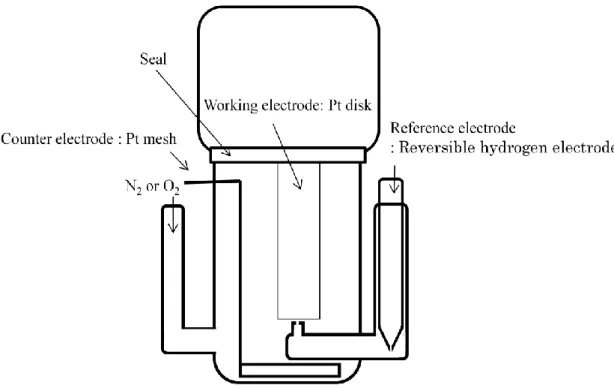
Fig. 1 shows a schematic drawing of three electrodes electrochemical cell. The

electrochemical measurements for PILs were conducted with a Pt electrode controlled

by an electrochemical analyzer (ALS-760B, BAS Inc.). The working electrode was Pt

disk (ϕ = 0.4 mm) electrode embedded in poly ether ether ketone (PEEK). Pt mesh and

(28)

Fig. 1 Schematic illustration of the cell.

(29)

reversible hydrogen electrode (RHE) were used as the counter and reference electrodes,

respectively. Before electrochemical measurements, the Pt disk electrode was polished using 0.3 μm alumina powder on a felt polishing pad and then was washed ultrasonically

in deionized water for five minutes. The deoxygenation of PILs was conducted by N

2

gas bubbling. The potential sweep measurements were conducted in a potential range from 1.2 V to 0 V vs. RHE at a scan rate of 50 mV s

-1

.

1-3. Results and discussion

Fig. 2 showed the

1

H NMR spectrum of the [dema][TfO]. As the reference peaks, the peaks at 0 ppm and 7.27 ppm were attributed to tetramethylsilane (TMS) and heavy chloroform (CHCl

3

), respectively. The four peaks appeared in other than the reference peaks. The peak at 8.72 ppm is assigned to the N-H proton. The peaks at 1.40 ppm, 2.84 ppm and 3.26 ppm are attributed to protons marked as a, b and c, respectively.

Fig. 2 also showed the integration of those four peaks. From the comparison of

integration, it was correspond to each department of structural formula in Fig. 2. Similar

results of

1

H NMR were obtained at five ionic liquids synthesized. The result of

1

H

NMR spectra be also correspond to literatures [34, 35], it was concluded that the cation

of these ionic liquids were present as quaternary ammonium salt. On the other hand,

anions were confirmed by the peaks of

19

F NMR spectrum shown in Fig. 3, Fig. 4, Fig.

(30)

5, Fig. 6 and Fig. 7. The peak of

19

F NMR spectrum of [dema][TfO] was 78.46ppm. The peak of

19

F NMR of [dema][PfO] were 80.13pm and 118.53ppm. The peak of

19

F NMR of [dema][HfO] were 80.79ppm, 115.19ppm and 125.09ppm. The peak of

19

F NMR of [dema][TFSI] was 78.85ppm. The peak of

19

F NMR of [dema][BETI] were 78.97ppm and 117.25ppm. The results of

19

F NMR spectra were corresponding to literature [36].

From these results, five ionic liquids of the target were properly prepared.

The thermogravimetric traces of [dema][TfO], [dema][PfO], [dema][HfO],

[dema][TFSI] and [dema][BETI] under nitrogen are shown in Fig. 8. It was confirmed that

the prepared PILs are stable at 150 °C, which is one of the target temperatures of

non-humidifed PEFC operation. Their weight losses at 150 °C were less than 2 % in

nitrogen. Those PILs by equimolar mixing of [dema] and a different fluoroalkylsulfonic

acid in deionized water were synthesized. Therefore, it was considered that small amount

of water was still included even after drying at 100 °C under vacuum for 48 h and

appeared as the weight loss. After the gradual loss of water up to 250 °C, the PILs showed

rapid weight losses at higher than 300 °C. From the thermogravimetric traces, the

decomposition temperatures (T

d

) for [dema][TfO], [dema][PfO], [dema][HfO],

[dema][TFSI] and [dema][BETI] were estimated at 338 °C, 333 °C and 334 °C, 345 °C

(31)

Fig. 2

1

H NMR spectrum of [dema][TfO].

(32)

Fig. 3

19

F NMR spectrum of [dema][TfO].

(33)

Fig. 4

19

F NMR spectrum of [dema][PfO].

(34)

Fig. 5

19

F NMR spectrum of [dema][HfO].

(35)

Fig. 6

19

F NMR spectrum of [dema][TFSI].

(36)

Fig. 7

19

F NMR spectrum of [dema][TFSI].

(37)

Fig. 8 Thermogravimetric traces of [dema][TfO], [dema][PfO], [dema][HfO]

, [dema][TFSI], [dema][BETI] under nitrogen atmosphere, measured at 2 °C min

-1

0 20 40 60 80 100

100 150 200 250 300 350 400 450 500

[dema][TfO]

[dema][PfO]

[dema][HfO]

[dema][TFSI]

[dema][BETI]

We ight los s / %

Temperature /

o

C

(38)

Fig. 9 Differential scanning calorimetry of [dema][TfO], [dema][PfO], [dema][HfO]

, [dema][TFSI], [dema][BETI] under nitrogen atmosphere, measured at 5 °C min

-1

(39)

and 324 °C respectively. Thus, the influence decomposition of PILs in the measurements 120 °C could be eliminated. DSC of [dema][TfO], [dema][PfO], [dema][HfO], [dema][TFSI], [dema][BETI] under nitrogen atmosphere were shown in Fig. 9. DSC measurement was performed to check the ionic liquids property such as melting point and glass transition temperature. In general, ionic liquids cause supercooling when ionic liquids are cooling. Therefore, the melting point of ionic liquids is recorded below actual melting point. For this reasons, the DSC traces were recorded during the heating scans. The glass transition temperature was not observed in the three ionic liquids with an anion having fluoroalkyl sulfonic acids. In contrast, the glass transition temperature was observed in two ionic liquids having an anion having bis(fluoroalkylsulfonil)imide acids. As a results, [dema] [BETI] was the most lowest the melting point in five ionic liquids, and [dema][PfO] was the most highest melting point. By the way, the melting point of ionic liquids is not a function of the anions or cations molecular weight.

Watanabe et al. have reported that they synthesized ionic liquids with combination of the

[dema] and some different anions, and investigated the thermal property. As the results,

it was found that there was a tendency of the following matter. The lower the melting

point of anion material, the lower melting point of ionic liquids[38]. The melting point

of the anion source such as [TfOH], [PfOH], [HTFSI], [HBETI] using this study were

(40)

-40 °C, -50 °C, from 52 °C to 56 °C and 38 °C, respectively. The reports of melting point of [HfOH] could be found. However, it is expected to be higher melting point than [PfOH] in order to have longer fluoroalkyl chain lengths. In general, ionic liquids with large ionic radius are lower melting point because electrostatic interaction is so weak that the charge density decreases. The halogen elements such as F strongly attract electron, therefore, electrostatic interaction of the anion including many halogen elements is so weak that the charge density decreases. However, the melting point of the ionic liquids having fluoroalkyl chain was not dependent on the fluoroalkyl chain length of anion source. This result showed that the melting point of ionic liquids were not dependent on the melting point of anion source.

Fig. 10 shows the viscosity of [dema][TfO], [dema][PfO], [dema][HfO], [dema][TFSI], [dema][BETI]. It was found that the viscosity of all ionic liquids linearly decreased with increasing temperature.

The ionic conductivity was showed in Fig. 11 and Fig. 12. The value of ionic

conductivity of [dema][TfO] at 120 °C was the most large, and the value of ionic

conductivity was 52 mS cm

-2

. This [dema][TfO] value of ionic conductivity was larger

than report of Watanabe et al.[38]. One of the causes, it was considered that the

moisture obtained from Karl Fischer measurement was contributed increase of value of

(41)

Fig. 10 Viscosity of [dema][TfO], [dema][PfO], [dema][HfO], [dema][TFSI] and

[dema][BETI].

(42)

Fig. 11 Conductivity of [dema][TfO], [dema][PfO], [dema][HfO], [dema][TFSI] and

[dema][BETI].

(43)

Fig. 12 Arrhenius plot of conductivity of [dema][TfO], [dema][PfO], [dema][HfO],

[dema][TFSI] and [dema][BETI].

(44)

ionic conductivity. Generally, ionic conductivity is affected by the viscosity. However, there was little the difference between the viscosity of five types of ionic liquids at 90 °C or more, despite the difference between the ionic conductivity of five types of ionic liquids were unchanged. Influence of viscosity is decreased with increasing temperature because intermolecular force has been weak. However, it was considered that the magnitude of influence of viscosity was no much difference on the ionic liquids.

By the way, in view of the fluoroalkyl chain length, it was considered that ionic conductivity was affected by the molecular radius. In this case, it was considered that the difference of anion conduction contribute to ion conductivity since cation was same.

That is, anion of larger molecule was decreased ionic conductivity in order to move

slowly. According to report of H. Tokuda et al., diffusion rate of cation was faster than

that of anion in ionic liquids having the larger cation molecule size comparison of anion

molecule size [39]. Therefore, it was considered that the diffusion rate of anion directly

appeared in the difference of ionic conductivity because the cation conduction rate was

unchanged with increasing temperature. On the other hand, in view of the structures of

anion sources, the value of ionic conductivity in [dema][TfO] was close to that in

[dema][TFSI]. According to the definition of Hard and soft acis and bases (HSAB), both

[TfO]

-

and [TFSI]

are soft base. In addition, the acidity of [HTFSI] was stronger than

(45)

that of [TfOH] [38]. It is considered that the [TFSI]

has the structure which negative charge is delocalized compared to [TfO]

-

. Therefore, the interaction of between [TFSI]

and [dema]

+

was weaker than that of between [TfO]

and [dema]

+

. The activation energy was estimated from arrhenius plot shown in Fig. 12. The activation energy of ionic conductivity, [dema][TfO], [dema][PfO], [dema][HfO], [dema][TFSI], [dema][BETI ] became 18.6 KJ mol

-1

, 21.2 KJ mol

-1

, 24.5 KJ mol

-1

, 20.4 KJ mol

-1

, and 27.0 KJ mol

-1

, respectively .

Fig. 8 show the cyclic voltammograms of [dema][TfO], [dema][PfO], [dema][HfO], [dema][TFSI] and [dema][BETI] under N

2

atmosphere and O

2

atmosphere, respectively. The ORR in PILs is difference of between the current density

under O

2

atmosphere and the current density under N

2

atmosphere. The ORR onset

potential of three types of fluoroalkylsulfonic acids anion based PILs was between 1.0 V

to 0.8 V. On the other hand, The ORR onset potential of two types

bis(fluoroalkylsulfonil)imide acids anion based PILs was between 0.2 V to -0.2 V. In

general, the ORR process was carried out Pt surface by adsorption of oxygen transported

from bulk. Therefore, it was considered that the anion having fluoroalkylsulfonic acids was

easy to do desorption on Pt surface compare to anion having bis(fluoroalkylsulfonil)imide

acids. From those results, for application of PEFC electrolyte, it is considered that the PILs

(46)

having fluoroalkylsulfonic acids was better than PILs having bis(fluoroalkylsulfonil)imide

acids. The oxygen reduction current density magnitude is affected a number of factors such

as O

2

diffusion and O

2

solubility and Temperature. Therefore, the chapter 2 focused on the

[dema][TfO], [dema][PfO] and [dema][HfO] in particular, and investigated O

2

diffusion

and O

2

solubility in those PILs.

(47)

Fig. 13 Cyclic voltammograms on Pt in (a) [dema][TfO], (b) [dema][PfO], (c) [dema][HfO], (d) [dema][TFSI] and (e) [dema][BETI] under N

2

atmosphere and O

2

atmosphere at 45 ˚C.

(48)

1-4. Conclusions

A series of PILs from [dema] and three kinds of fluoroalkylsulfonic acids having different chain lengths (H-SO

3

(CF

2

)

n

F, n = 1~3) or two kinds of bis(fluoroalkylsulfonil)imide acids having different chain lengths (H-NS

2

O

4

(C

2

F

4

)

n

F

2

, n = 1~2) were synthesized. Those PILs was performed thermal analysis, and the decomposition temperature (T

d

) of all PILs was from 320 °C to 340 °C. The melting point (T

m

) of [dema][PfO] was higher than [dema][HfO], it’s value was 37 °C and 49 °C, respectively. Therefore, even if the ionic liquids with an anion having longer fluoroalkyl chains lengths was synthesized, ionic liquids with low melting point was not necessarily be made.

As the results of the activation energy of ionic conductivity, [dema][TfO],

[dema][PfO], [dema][HfO], [dema][TFSI], [dema][BETI ] became 18.6 KJ mol

-1

, 21.2

KJ mol

-1

, 24.5 KJ mol

-1

, 20.4 KJ mol

-1

, and 27.0 KJ mol

-1

, respectively . From the

results of cyclic voltammetry of PILs, Onset potential of ORR in PILs having

fluoroalkylsulfonic acids were more electropositive potential than that of ORR in PILs

having bis(fluoroalkylsulfonil)imide acids.

(49)

References

[1] C. W. Lee, Tetrahedron Lett. 40 (1999) 2461-2462.

[2] T. Fischer, A. Sethi, T. Welton, J. Woolf, Tetrahedron Lett. 40 (1999) 793-796.

[3] L. Xu, W. Chen, J. Xiao, Organometallics, 19 (2000) 1123-1127.

[4] L. Xu, W. Chen, J. Ross, J. Xiao, Org. Lett. 3 (2001) 295-297.

[5] V. P. W. Böhm, W. A. Herrmann, Chem. Eur. J. 6 (2000) 1017-1025.

[6] C. P. Mehnert, N. C. Dispenziere, R. A. Cook, Chem. Commun. (2002) 1610-1611.

[7] C. J. Mathews, P. J. Smith, T. Welton, Chem. Commun. (2000) 1249-1250.

[8] V. L. Boulaire, R. Grée, Chem. Commun. (2000) 2195-2196.

[9] S. T. Handy, X. Zhang, Org. Lett. 3 (2001) 233-236.

[10] J. Ross, J. Xiao, Green Chem. 4 (2002) 129-133.

[11] K.-S. Yeung, M. E. Farkas, Z. Qiu, Z. Yang, Tetrahedron Lett. 43 (2002) 5793-5795.

[12] A. Stark, B. L. MacLean, R. D. Singer, J. Chem. Soc., Dalton Trans. (1999) 63-66.

[13] C. J. Adams, M. J. Earle, G. Roberts, K. R. Seddon, Chem. Commun. (1998) 2097-2098.

[14] A. L. Monteiro, F. K. Zinn, R. F. de Souza, J. Dupont, Tetrahedron Asymmetry 8

(1997) 177-179.

(50)

[15] G. W. Kabalka, R. R. Malladi, Chem. Commun. (2000) 2191-2191.

[16] J. L. Reynolds, K. R. Erdner, P. B. Jones, Org. Lett. 4 (2002) 917-919.

[17] J. S. Yadav, B. V. S. Reddy, A. K. Basak, A. V. Narsaiah, Tetrahedron Lett. 44 (2003) 1047-1050.

[18] L. C. Tome, D. Mecerreyes, C. S. R. Freire, L. P. N. Rebelo, I. M. Marrucho. J.

Membr. Sci. 428 (2013) 260-266.

[19] J. J. Close, K. Farmer, S. S. Moganty, R. E. Baltus, J. Membr. Sci. 390-391(2012) 201-210.

[20] K. Friess, J. C. Jansen, F. Bazzarelli, P. Izák, V. Jarmarová, M. Kačírková, J.

Schauer, G. Clarizia, P. Bernardo, J. Membr. Sci. 415-416 (2012) 801-809.

[21] E. Santos, J. Albo, C. I. Daniel, C. A. M. Portugal, J. G. Crespo, A. Irabien, J.

Membr. Sci. 430 (2013) 56-61.

[22] P. Jindaratsamee, A. Ito, S. Komuro, Y. Shimoyama, J. Membr. Sci. 423-424 (2012) 27-32.

[23] G. Zarca, I. Ortiz, A. Urtiaga, J. Membr. Sci. 438 (2013) 38-45.

[24] A. Guerfi, M. Dontigny, P. Charest, M. Petitclerc, M. Lagacé, A. Vijh, K. Zaghib, J.

Power Sources 195 (2010) 845-852.

[25] L. Zhao, J. Yamaki, M. Egashira, J. Power Sources 174 (2007) 352-358.

(51)

[26] J. Reiter, M. Nadherna, Electrochim. Acta 71 (2012) 22-26.

[27] S. Fang, Y. Tang, X. Tai, L. Yang, K. Tachibana, K, Kamijima, J. Power Sources 196 (2011) 1433-1441.

[28] J. Hassoun, A. Fernicola, M. A. Navarra, S. Panero, B. Scrosati, J Power Sources 195 (2010) 574-579.

[29] S. Lee, T. Yasuda, M. Watanabe, J. Power Sources 195 (2010) 5909-5914.

[30] M. Guo, J. Fang, H. Xu, W. Li, X. Lu, C. Lan, K. Li, J Membr. Sci. 362 (2010)

97-104.

[31] H. Deligöz, M. Yilmazoğlu, J. Power Sources 196 (2011) 3496-3502.

[32] C. Yue, D. Fang, L. Liu, T. Yi. J. Molecular liquids 163 (2011) 99-102.

[33] H. Munakata, T. Tashita, M. Haibara, K. Kanamura, ECS trans. 33 (2010) 463-469.

[34] K. Mori, T. Kobayashi, K. Sakakibara, K. Ueda, Chem. Phys. Lett. 552 (2012) 58-63.

[35] H. Li, F. Jiang, Z. Di, J. Gu, Electrochim. Acta 59 (2012) 86-90.

[36] I. V. Kuvychiko, J. B. Whitaker, B. W. Larson, T. C. Folsom,N. B. Shustova, S. M.

Avdoshenko, Y. Chen, H. W.en, X. Wang, L. Dunsch, A. A. Popov, O. V. Boltalina, S. H.

Strauss, Chem. Sci. 3 (2012) 1399-1407.

[37] U. A. Rana, M. Forsyth, D. R. MacFarlane, J. M. Pringle, Electrochim. Acta 84

(52)

(2012) 213-222.

[38] H.Nakamoto, M. Watanabe, Chem. Commun. (2007) 2539-2541.

[39] H. Tokuda, K. Hayamizu, I. Md. A.B. H. Susan, M. Watanabe, J. Phys. Chem. B.

108 (2004) 16593-16600.

(53)

Chapter 2

Temperature dependence of solubility and diffusion coefficient of oxygen in protic ionic liquids having different fluoroalkyl chain lengths

2-1. Introduction

Polymer electrolyte fuel cell (PEFC) is compact and has high energy density compared with other kinds of fuel cells. As the electrolytes for PEFC, fluoropolymer electrolytes such as Nafion

®

have been used because of high proton conductivity and good chemical stability. However, those electrolyte membranes have to be used under humidified conditions in order to maintain high proton conductivity. Therefore, the PEFC system becomes large to equip humidifying apparatus. As a result, PEFC operation is still limited up to 80 °C although the catalyst activity is strongly reduced by CO poisoning at low temperatures. Thus, new electrolyte materials, which can be used without humidification at higher temperatures than 100 °C, are needed [1-5].

Ionic liquids, which are molten salts at room temperature, have attracted

(54)

considerable attention as PEFC electrolyte materials at intermediate temperatures (higher than 100 °C) under non-humidified conditions because of their special characteristics such as non-volatile, non-flammability, high thermal stability and electrochemical stability. The electrolyte used for PEFC needs proton conductivity. Thus, ionic liquids investigated for PEFC are generally called as protic ionic liquids (PILs), which can be synthesized simply by neutralization of Brönsted acid and base. So far, various kinds of PILs have been synthesized. They are relatively stable against water and air [6]. However, the overvoltage of oxygen reduction reaction (ORR) on conventional platinum catalyst in those PILs is much larger than that in Nafion

®

[7].

In order to utilize PILs to fuel cells, the characteristics of PILs as electrolytes have

been extensively studied. Watanabe et al. has studied PILs that were synthetized from

various kinds of imidazolium-based or ammonium-based cations and various strong acid

or super acid anions [8-13]. They have reported that N,N-diethylemethyleammonium

trifluoromethanesulfonate ([dema][TfO]) is appropriate for ORR [12, 13]. In addition, it

has been reported that the PEFC applied with [dema][TfO] showed an output density of

more than 100 mW cm

-2

[14]. Hagiwara et al. has developed fluorohydrogenate anion

([FHF

-

]) based PILs having layered crystal structures. Both cation and anion transports in

those PILs are so fast and the proton transport is supported by [FHF

-

] anion rather than by

(55)

cation. Therefore, [FHF

-

]-based PILs are preferable as fuel cell electrolytes. Actually, it has been reported that the single cell test using [FHF

-

]-based PILs shows the power density of 200 mW cm

-2

at 80 °C. It has been also reported that the cell operation at 130 °C under non-humidified condition [15-18]. In addition to those researches, studies on electrolyte membranes impregnated with PILs have been recently focused [19-23].

So far, we have focused on the ORR in PILs which were synthetized by

combination of anions having different fluoroalkyl chain lengths and [dema] cation. The

ORR in those PILs on Pt electrode has been analyzed by in-situ infrared spectroscopy

(in-situ FT-IR). From this measurement, it has been found that the adsorption and

desorption behavior of the anion in PILs strongly affects the ORR activity. This result

shows that the ionic liquid comprising an anion weakly absorbed on Pt surface, which can

be easily released by applying a potential, is appropriate for the ORR [24]. In this study,

we synthesized a series of PILs from [dema] and three kinds of fluoroalkylsulfonic acids

having different chain lengths (H-SO

3

(CF

2

)

n

F, n = 1~3), and investigated the effect of

fluoroalkyl chain length on the solubility and diffusion coefficient of oxygen in the

[dema]-based PILs to discuss the appropriate design of PILs for intermediate temperature

fuel cells.

(56)

2-2. Experimental

2-2-1. Preparation of protic ionic liquids with different fluoroalkyl chain lengths

As anion sources, trifluoromethanesulfonic acid ([TfO], Tokyo Kasei Ltd.), pentafluoroethanesulfonic acid ([PfO], Mitubishi Materials Corp.) and heptafluoropropanesulfonic acid ([HfO], Mitubishi Materials Corp.) were used. These were respectively mixed with an equimolar of N,N-diethelymethelamine ([dema], Tokyo Kasei Ltd.) as a cation source in deionized water to prepare PILs with different fluoroalkyl chain lengths by neutralization method, in which the byproduct is only water. The obtained PILs were then dried at 100 °C under vacuum at least for 48 h before use.

2-2-2. Characterizations

The viscosity was measured with a viscometer with (thermosel LVT, Brookfield Ltd.). The measurement temperature was controlled from 30 °C to 120 °C. For each sample, the measurement was carried out at least three times for accurate evaluation.

Electrochemical measurements for PILs were conducted using a glass cell

equipped with a rotating disk electrode (RDE) system. A rotating Pt disk (ϕ = 0.4 mm)

embedded in poly ether ether ketone (PEEK) was used as the working electrode. Pt mesh

and reversible hydrogen electrode (RHE) were used as the counter and reference electrodes,

(57)

respectively. Before electrochemical measurements, the Pt disk electrode was polished using 0.3 μm alumina powder on a polishing felt pad and then was washed ultrasonically in deionized water for five minutes. The deoxygenation of PILs was conducted by nitrogen gas bubbling. The potential sweep measurements were conducted using an electrochemical analyzer (ALS-760B, BAS Inc.) in a potential range from 1.1 V to 0.2 V vs. RHE at a scan rate of 5 mV s

-1

by changing the rotation speed of Pt disk electrode from 100 rpm to 400 rpm. The chronocoulometry was also performed using the RDE. The electrode potential was changed from the open circuit potential (OCP) to 0.1 V, at which the ORR in PILs is governed by the diffusion of oxygen to the electrode surface. The rotation speed of RDE was changed from 100 rpm to 900 rpm. The analysis of electrochemical parameters of ORR in PILs was carried out according to the following equations provided by chronocoulometry under the convection control of the solution [25, 26],

Q = Q

intercept

+ I

L

t (1)

Q

intercept

= Q

adsorption

+Q

δ

(2)

Q

δ

= 0.3764nFACδ (3)

I

L

= j

L

A = nFADC / δ (4)

where Q is electric charge, Q

intercept

is the intercept of the straight line of Q-t plot (eq.

(1)), I

L

is the diffusion limited current, t is the time, Q

δ

is the charge passed by

(58)

electrolysis of species present initially in the hydrodynamic boundary, Q

adsorption

is the charge passed by electrolysis of adsorbed species, n is the reaction electron number, F is

the Faraday constant, A is the electrode surface area, C is the solubility of oxygen, D is the diffusion coefficient of oxygen, δ is the thickness of hydrodynamic boundary, and j

L

is the diffusion limited current density. Furthermore, the thickness of hydrodynamic boundary, which is the diffusion layer discussed by Newman et al., is given by the

following equation [26-28].

δ = 1.610 D

1/3

ν

1/6

ω

-1/2

( 1+0.2980Sc

-1/3

+0.14514Sc

-2/3

) (5)

where ν (cm

2

s

-1

) is kinetic viscosity of the solution, ω (s

-1

) is electrode rotation speed and Sc (= ν/D) is Schmidt number. The reaction electron number n was estimated by linear sweep voltammetry using a rotating Pt ring-Pt disk electrode. The collection efficiency between the ring and disc electrodes was estimated using 0.1 mol dm

-3

KCl aqueous solution containing with 1 mmol dm

-3

ferricyanide, in which the potential of ring electrode was fixed at 1.4 V vs. RHE.

3-1. Results and discussion

The viscosity, density and kinetic viscosity of [dema][PfO] and [dema][HfO] are

shown in Table 1. The kinetic viscosity is a necessary parameter to calculate the diffusion

(59)

coefficient and solubility of oxygen in PILs. The kinetic viscosity is given by the following

equation,

ν = η / ρ (6)

where η is viscosity, ρ is density and ν is kinetic viscosity. It was difficult to measure viscosity, density and kinetic viscosity of [dema][PfO] at 30 °C due to its crystallization.

Therefore, the measurement for [dema][PfO] was performed at 45 °C and higher temperatures. In contrast, [dema][HfO] having a longer fluoroalkyl chain than

[dema][PfO], was not crystallized even at room temperature. Thus, those parameters were able to be measured. As listed in Table 1, the viscosities of [dema][PfO] and [dema][HfO]

decreased with increasing temperature, and their kinetic viscosities also decreased. The viscosity of [dema][PfO] is much smaller than that of [dema][HfO] at low temperatures. At 60 °C, the viscosities of both PILs are significantly different. However, the difference between them becomes smaller at higher temperatures. This result indicates that the anion-cation interactive force becomes smaller and does not influence much on the viscosity at high temperatures. Therefore, it is expected that high viscosities of PILs may be canceled in fuel cell operation at higher than 100 °C.

Fig. 1 shows the linear-sweep voltammograms of Pt RDE at different rotation

speeds from 100 rpm to 400 rpm in [dema][PfO] and [dema][HfO] saturated with oxygen

(60)

Table 1 Viscosity (η), density (ρ) and kinetic viscosity (ν) of [dema][PfO] and [dema][HfO] at different temperatures.

Sample T / °C η / mPa s ρ / g cm

-3

ν / cm

2

s

-1

[dema][PfO] 45 28.9 1.35 0.214

60 19.3 1.35 0.143

75 12.1 1.34 0.091

90 9.8 1.34 0.073

105 8.1 1.34 0.060

120 5.5 1.33 0.041

[dema][HfO] 30 93.3 1.43 0.668

45 47.8 1.42 0.317

60 27.2 1.41 0.160

75 16.9 1.41 0.094

90 11.3 1.41 0.062

105 7.9 1.40 0.046

120 5.8 1.40 0.035

(61)

speeds from 100 rpm to 400 rpm in [dema][PfO] and [dema][HfO] saturated with oxygen at 45 °C. The reduction current for ORR corresponds to the difference between current densities obtained under nitrogen and oxygen atmospheres. The diffusion limited current density at 0.2 V increased according to the rotation speed. A similar tendency was observed at higher than 45 °C. The diffusion limiting current density in [dema][PfO] was higher than that in [dema][HfO] at all the rotation speeds. This result can be understood from lower viscosity of [dema][PfO] than that of [dema][HfO] since oxygen diffusion is strongly influenced by the viscosity. However, the influence of oxygen solubility should be took into account for precise discussion on ORR in PILs. From the shapes of voltammograms in Fig. 1, the cathodic current at 0.2 V is regarded as diffusion limiting current density at each rotation speed. Based on this estimation, Levich plots for ORR in [dema][PfO] and [dema][HfO] were made using the current densities at 0.2 V as shown in Fig. 2. The obtained straight lines indicate that the ORR is controlled by oxygen diffusion [28], and the slope of straight line became steeper with increasing temperature.

Fig. 3 shows hydrodynamic chronocoulometric curves of ORR on Pt RDE in [dema][PfO] and [dema][HfO] at 45 °C. Q-t curve after several seconds exhibited a linear relationship. This straight line corresponds to Eq. (1) as reported by the literature [27]. Fig.

4 shows the plots of Q

intercept

against ω

-1/2

. Linear relations were observed for both

(62)

Fig. 1 Hydrodynamic voltammograms for the ORR on Pt-disk electrode in (a)

[dema][PfO] and (b) [dema][HfO] under nitrogen and oxygen atmospheres at 45 °C,

measured at a scan rate of 0.005 V s

-1

.

(63)

[dema][PfO] and [dema][HfO]. Q

adsorption

is independent from the rotation speed of RDE, which is determined from the intercept of plot. Then, Q

δ

at each ω is calculated from Eq.

(2). The slope of I

L

- ω

-1/2

plot was obtained from Fig. 2. The values of C and D can be determined by combining the Eqs. (3)~(5) after the determination of reaction electron number n. Two electron or four electron process is possibly expected for ORR. We estimated the reaction electron number by linear sweep voltammetry using a rotating Pt ring-Pt disk electrode with a collection efficiency of 0.41. No current was detected on the ring electrode at 30 °C, 45 °C and 60 °C in [dema][PfO] and [dema][HfO] during the potential sweep of the disk electrode from 1.2 V to 0.1 V vs. RHE. Walsh et al. have reported that less than 0.1 % of total ORR proceeds in two-electron reaction in [dema][TfO] at 50 °C [29]. Actually, we also confirmed no ring current in [dema][TfO]

even at 120 °C. Therefore, the reaction electron number was assumed to be 4.

Fig. 5 shows the temperature dependences of oxygen solubility in [dema][PfO]

and [dema][HfO], In general, oxygen solubility in liquid is known to decrease with

increasing temperature. Actually, the similar phenomena appeared for both PILs. The

oxygen solubility in [dema][PfO] was lower than that in [dema][HfO] at all the

temperatures tested in this study, suggesting that the oxygen solubility increases with

increasing the fluoroalkyl chain length of anion. High solubility of oxygen in liquid

(64)

Fig. 2 Levich plots of the limiting ORR current on Pt (0.2 V vs. RHE) in (a)

[dema][PfO] and (b) [dema][HfO] at different temperatures.

(65)

Fig. 3 Hydrodynamic chronocoulometric responses of the ORR on Pt-disk electrode in

(a) [dema][PfO] and (b) [dema][HfO] at 0.2 V vs. RHE at 45 °C.

(66)

Fig. 4 Q

intercept

vs. ω

-1/2

plots for the ORR on Pt in (□) [dema][PfO] and (○) [dema][HfO]

at 45 °C.

(67)

fluorocarbons has been well known and studied in various research fields [32-34]. This property is focused particularly in the biomedical field, and many kinds of liquid fluorocarbons have been investigated as oxygen carriers such as an artificial blood. The higher oxygen solubility in liquid fluorocarbons than in the analogous hydrocarbons is explained by low polarizability of fluorine atom. For example, the oxygen solubility in n-hexadecafluoroheptane (n-C

7

F

16

) is over three times higher than in n-heptane (x-C

7

H

16

) [35]. In addition, it has been reported that linear perfluoroalkanes have higher oxygen solubility when compared to cyclic and polycyclic perfluoroalkanes [36]. In fact, the oxygen solubility in the PIL was greatly improved by lengthening the fluoroalkyl chain of anion from [TfO] to [PfO] and [HfO]. Therefore, to use an anion source having a linear and long fluoroalkyl chain is expected as one of PIL designs for fuel cells.

Fig. 6 shows Arrhenius plots of the oxygen diffusion coefficient in [dema][PfO]

and [dema][HfO]. The oxygen diffusion coefficient in liquid generally increases with increasing temperature, which is an opposite manner to the oxygen solubility in liquid.

Both in [dema][PfO] and [dema][HfO], the oxygen diffusion coefficient increased with

increasing temperature. In addition, it decreased with increasing the fluoroalkyl chain

length of anion. The activation energy of oxygen diffusion coefficient in [dema][PfO] and

[dema][HfO] were calculated to be 35.5 KJ mol

-1

and 38.4 KJ mol

-1

, respectively. This

(68)

Fig. 5 Temperature dependences of the oxygen solubility in (□) [dema][PfO] and (○)

[dema][HfO].

(69)

result suggests that the anion with shorter fluoroalkyl chain is preferable for oxygen diffusion in PILs composed of [dema] cation. It is also noteworthy that the estimated values for [dema][PfO] and [dema][HfO] are close to that in Nafion

®

(35 KJ mol

-1

) [31].

Therefore, the oxygen diffusion mechanisms in the prepared PILs are expected to be similar to that in conventional Nafion

®

.

Table 3 shows the solubility and diffusion coefficient of oxygen in the prepared PILs and Nafion

®

at fuel cell operation temperatures. As discussed above, those values in PILs changed with the fluoroalkyl chain length of anion. Namely, the oxygen solubility increased as increasing the fluoroalkyl chain length. In contrast, the longer fluoroalkyl chain length decreased oxygen diffusion coefficient. By the way, the product of C and D is considered as a transmission coefficient of oxygen through a solid electrolyte membrane.

When this number is large, the crossover of oxygen occurs in a fuel cell. As the fluoroalkyl

chain length of anion became longer, the C·D value in PILs decreased, and the smaller

value than that in Nafion

®

was obtained in [dema][HfO]. From this result, it can be said

that [dema][HfO] is a promising PIL to be adapted to a fuel cell electrolyte. However, it is

difficult to use liquid electrolytes directly in conventional PEFC system. Thus, the

incorporation with self-standing matrices such as porous membranes is basically required

[38-40]. So far, some composite electrolyte membranes incorporated with liquid-type

(70)

electrolyte materials have been developed [14, 17, 41-49]. The incorporation techniques

for them is expected to be applicable to develop new composite membranes using

[dema][HfO] for intermediate temperature fuel cells.

(71)

Fig. 6 Arrhenius plots of oxygen diffusion coefficient in (□) [dema][PfO] and (○)

[dema][HfO].

(72)

Table 3 The solubility (C) and diffusion coefficient (D) of oxygen in the PILs used this

study and Nafion

®

.

Sample C / mmol dm

-3

D / 10

-6

cm

2

s

-1

C·D / 10

-12

mol cm

-1

s

-1

T / °C Ref.

[dema][TfO] 0.95 55.4 52.6 120 This work

[dema][PfO] 8.66 2.51 21.7 120 This work

[dema][HfO] 10.5 1.48 15.5 120 This work

Nafion

®

117 14.2 1.32 18.7 80 [37]

(73)

2-4. Conclusions

The diffusion coefficient and solubility of oxygen in [dema][PfO] and

[dema][HfO] were determined by the combination of linear-sweep voltammetry and

hydrodynamic chronocoulometry. The diffusion coefficients at 120 °C in [dema][PfO] and

[dema][HfO] were lower than that in [dema][TfO]. On the other hand, the solubilities were

larger than that in [dema][TfO]. These results show that the diffusion coefficient decreases

with increasing the fluoroalkyl chain length of anion. In contrast, the solubility has the

opposite dependency on the fluoroalkyl chain length. From the viewpoint of intermediate

temperature fuel cell application, [dema][HfO] is the most promising electrolyte in the

[dema] cation-based PILs tested in this study since it has a smaller permeability coefficient

of oxygen than that in Nafion

®

. The advantage of PILs is expected to be enhanced with

increasing temperature, which was revealed as the temperature dependencies of oxygen

diffusion coefficient and solubility.

(74)

References

[1] R. Lan, X. Xu, S. Tao, J. T. S. Irvine, J. Power Sources 195 (2010) 6983-6987.

[2] J. L. Lu, Q. H. Fang, S. L. Li, S. P. Jiang, J. Membr. Sci. 427 (2013) 101-107.

[3] A. Eguizábal, J. Lemus, M. P. Pina, J. Power Sources 222 (2013) 483-492.

[4] X. Zhang, S. Chen, J.Liu, Z. Hu, S. Chen, L. Wang, J. Membr. Sci. 371 (2011) 276-285.

[5] K. Okamoto, K. Yaguchi, H. Yamamoto, K. Chen, N. Endo, M. Higa, H. Kita, J.

Power Sources 195 (2010) 5856-5861.

[6] U. A. Rana, M. Forsyth, D. R. MacFarlane, J. M. Pringle, Electrochim. Acta 84 (2012) 213-222.

[7] A. Noda, M. A. B. H. Susan, K. Kudo, S. Mitsushima, K. Hayamizu, M. Watamabe, J. Phys. Chem. 107 (2003) 4024-4033.

[8] A. Noda, K. Hayamizu, M. Watanabe, J. Phys. Chem. 105 (2001) 4603-4610.

[9] M. A. B. H. Susan, A. Noda, S. Mitsushima, M. Watanabe, Chem. Commun. (2003) 938-939.

[10] H. Tokuda, K. Hayamizu, K. Ishii, M. A. B. H. Susan, M. Watanabe, J. Phys. Chem.

B 108 (2004) 16593-16600.

[11] H. Tokuda, K. Hayamizu, K. Ishii, M. A. B. H. Susan, M. Watanabe, J. Phys. Chem.

Fig. 2 Schematic diagram of MEA for PEFC
Fig. 3 The picture on photograph of ionic liquid
Fig. 1 Schematic illustration of the cell.
Fig. 3  19 F NMR spectrum of [dema][TfO].
+7

参照

関連したドキュメント

Abstract Railway companies in the Tokyo Metropolitan Region have provided many residential areas, and the companies that originally focused on housing development

Next, let us observe that it follows from Lemma 2.4 and [1], Proposition 3.2, that the zero divisor of the square Hasse invariant of this nilpotent indigenous bundle coincides with

In § 6, we give, by applying the results obtained in the present paper, a complete list of nilpotent/nilpotent admissible/nilpotent ordinary indigenous bundles over a projective

See [10] on traveling wave solutions in bistable maps, [2] time-periodic nonlocal bistable equations, [1] time-periodic bistable reaction-diffusion equations, e.g., [3, 4, 7, 9,

proof of uniqueness divides itself into two parts, the first of which is the determination of a limit solution whose integral difference from both given solutions may be estimated

2 To introduce the natural and adapted bases in tangent and cotangent spaces of the subspaces H 1 and H 2 of H it is convenient to use the matrix representation of

In recent work [23], authors proved local-in-time existence and uniqueness of strong solutions in H s for real s > n/2 + 1 for the ideal Boussinesq equations in R n , n = 2, 3

Correspondingly, the limiting sequence of metric spaces has a surpris- ingly simple description as a collection of random real trees (given below) in which certain pairs of