LONGITUDINAL TRANSPORT OF SUSPENDED SOLIDS DURING FLOOD
K. Sato1 and Y. Watanabe1
ABSTRACT: River life is affected by sediment, nutrients and other factors related to the formation of ecosystems. It is necessary to understand the status of these factors as well as their changes that may result from river channel alterations. It has been pointed out that most of the nutrients stored in river channels are absorbed by fine sands and transported in times of flood before being redeposited elsewhere. However, the behavior during flood of such very fine sands that have absorbed nutrients has yet to be sufficiently clarified, and its earliest possible clarification is required to help promote future river projects. This report considers the flow down process of suspended solids, based on data obtained from flood observation of the Mukawa River and subsequent survey on riverbank deposits. An unsteady flow and bed variation calculation model is proposed, and is found to reproduce the behavior of suspended solids at the time of flood.
1. INTRODUCTION
Check dam construction, river improvement and other factors have hindered sediment supply to drainage basins, which has led to the serious social problems of riverbed degradation and coastal erosion. Sediment has been discharged experimentally from dams to address their sediment problems; however, this has its own problems in that the suspended solids deposit and adversely affect the downstream ecosystem. Flood control by river dams also has been altering the downstream ecosystem by producing a stable flow regime that has stabilized the riverbed topography. To address these issues, it is necessary to clarify phenomena concerning movement of sediment including very fine sand through the drainage basin.
The presence and growth of flora and fauna in and around rivers relate closely to sediment, nutrient salts and other factors, which all form the basis of the river ecosystem. It has been pointed out that transport and storage of nutrient salts in a river channel occur predominately through absorption by suspended solids during flood1). For these reasons, studies have been
1 Civil Engineering Research Institute, Hokkaido Development Bureau, Japan
0 10 20 30 km
Hobetsu River Hobetsu Bridge
(KP.40.7)
Eiwa Bridge (KP.26.0) Mukawa Bridge
(KP.2.6) N
Pacific Ocean
Mukawa River Kosei Bridge
Pankeshuru River
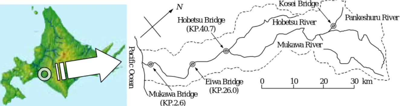
Figure 1 The Mukawa River drainage basin
attempting to clarify the precise situation of sediment, nutrient salts and other factors, and changes in their behaviors caused by alterations in river channels, for conservation of the river environment.
Behavior of wash load (very fine sand and other components) during flood has not been elucidated thoroughly. Thus it requires clarification, toward solution of the abovementioned problems.
This study focuses on the phenomenon whereby the suspended solids peak before the water level during flood. Based on observation of the suspended solids concentration in flowing water during flood and survey of riverbank sediments before and after flood in the Mukawa River drainage basin (Figure 1), and using riverbed evolution calculation of one- dimensional unsteady flow, we investigated the downstream transportation of suspended solids during flood and the relationship between suspended solids and riverbank sediments.
2. PEAK TIME OF WATER LEVEL AND SUSPENDED SOLIDS CONCENTRATION
The transport distance of sediment from ground to river is shorter in upstream areas, which are likely to be mountainous, than in downstream areas, which are likely to be flatter.
Therefore, in upstream river areas, the suspended solids concentration peaks at the same time as the discharge. Figure 2 shows the results of observations at Kosei Bridge over the Pankeshuru River, at the upper reaches of the Mukawa River2). The figure shows that changes in the concentration of suspended solids and in the water level shift almost in phase.
The transport velocity for suspended solids from the upper reaches roughly equals the flow velocity. However, if the waves are regarded as kinematic waves traveling in a long rectangular channel, then the velocity at which the flood waves (i.e., the changes in water
341.0 341.5 342.0 342.5
00/4/6 0:00 00/4/6 6:00 00/4/6 12:00 00/4/6 18:00 00/4/7 0:00 Time
Water Elevation (m)
0 500 1000 1500
Concentration of SS (mg/L)
Water Level Concentration of SS
Figure 2 Changes in the water level and the concentration of suspended solids with time at the upper reaches of the Mukawa River (Kosei Bridge)
Water Level Concentration of SS
Upper reachesLower reaches
Time lag
Time
Velocity of flood waves Flow velocity Figure 3 The propagation of flood waves and
suspended solids
1.0 1.5 2.0 2.5 3.0 3.5
98/4/13 18:00 98/4/14 0:00 98/4/14 6:00 Time
Water Level(m)
0 1000 2000 3000 4000 5000
Concentration of SS(mg/L)
Water level at Hobetsu Bridge-52m Water level at Mukawa Bridge Concentration of SS at Hobetsu Bridge Concentration of SS at Mukawa Bridge
Figure 4 Changes in the water level and the concentration of suspended solids with time at the lower reaches of the Mukawa River (Hobetsu Bridge, Mukawa Bridge)
level) propagate downstream is 5/3 of the flow velocity. These facts suggest that suspended solids supplied to the upper reaches of a river channel should propagate downstream more slowly than the flood waves (Figure 3).
However, such a lag is rarely observed; in fact, the peak of suspended solids concentration usually precedes the peak of water level3). Figure 4 shows the relationship between changes in suspended solids concentration and changes in water level with time at Mukawa Bridge and Hobetsu Bridge over the Mukawa River1). No large tributaries join the river between the two points. Mukawa Bridge is 2.6 km from the river mouth; Hobetsu Bridge is 40.7 km from the river mouth. In this case, too, the suspended solids concentration peaks before the water level. The times it takes for the water level and for the suspended solids concentration to propagate from one point to the other are shown in Figures 5 and 6, respectively. Judging from changes with time near the peak, the time of propagation is about 5 - 6 hours for both the water level and the suspended solids concentration. This indicates that both the water level and the suspended solids concentration propagated downstream at the same velocity of approximately 2 m/s between Hobetsu Bridge and Mukawa Bridge and that the peak suspended solids concentration preceded the peak water level.
One reason for this is thought to be that fine sand grains that become suspended solids are supplied from a riverbed with an increase in the tractive force on the riverbed during flood.
However, very fine sand, which is the main component of suspended solids, has a grain diameter of less than 0.1 mm and is not usually found in a riverbed. If we assume that wash load is produced in a place that is not ordinarily exposed to flowing water (a bare slope, or a
54.5 55.0 55.5
98/4/13 18:00 98/4/14 0:00 98/4/14 6:00 98/4/14 12:00 Time
Water level; Hobetsu Bridge(m)
2.5 3.0 3.5
Water level; Mukawa Bridge(m)
Water level at Hobetsu Bridge(+0hr) Water level at Hobetsu Bridge(+4hr) Water level at Hobetsu Bridge(+5hr) Water level at Hobetsu Bridge(+6hr) Water level at Hobetsu Bridge(+7hr) Water level at Mukawa Bridge
Figure 5 Time taken for water level to propagate from Hobetsu Bridge to Mukawa Bridge
Figure 6 Time taken for suspended solids concentration to propagate from Hobetsu Bridge to Mukawa Bridge
0 1000 2000 3000 4000 5000
98/4/13 18:00 98/4/14 0:00 98/4/14 6:00 98/4/14 12:00 Time
SS Concentration; Hobetsu Bridge(mg/L)
0 1000 2000 3000 4000 5000
SS Concentration; Mukawa Bridge(mg/L)
Concentration of SS at Hobetsu Bridge(+0hr) Concentration of SS at Hobetsu Bridge(+4hr) Concentration of SS at Hobetsu Bridge(+5hr) Concentration of SS at Hobetsu Bridge(+6hr) Concentration of SS at Hobetsu Bridge(+7hr) Concentration of SS at Mukawa Bridge
riverbank at the mountainous upper reaches) and that the produced wash load is transported downstream largely unchanged, then the clarification of the suspended solids supply source is necessary toward explaining the phenomenon observed at the lower reaches, whereby the suspended solids concentration peaks before the water level.
3. BEHAVIOR OF SUSPENDED SOLIDS OBTAINED BY UNSTEADY FLOW CALCULATION
We calculated the riverbed evolution5) using the CIP method4) for one-dimensional unsteady flow, to clarify how suspended solids behave between Hobetsu Bridge and Mukawa Bridge. Although this study focuses on the behavior of suspended solids, the calculation of riverbed evolution included sediment of other grain sizes, to account for the sheltering effects exerted by particles of larger grain size and exchanges with bed materials. The CIP method uses spline interpolation to calculate finite differences. This method has extremely small numerical diffusion when used to calculate the propagation of waveforms. Therefore, it is effective in calculating flood waves.
(1) Outline of the model
The motion and the continuity of unsteady flow in an open channel are expressed by equations (1) and (2), respectively.
( ) 2
3 4 2 2
2
1
−
∂ +
−∂
=
∂ + ∂
∂
∂
A Q R
n x h A
Q x g A Q t g
η
α (1)
=0
∂ +∂
∂
∂ x Q t
A (2)
where, Q : discharge, g : gravitational acceleration, t : time, h : water depth, η : height of riverbed, x : longitudinal distance, n : Manning's coefficient of roughness, R : hydraulic radius, A : cross sectional area and α : energy correction coefficient.
The evolution calculation of riverbed includes suspended solids and bedload, because the calculation seeks to clarify the behavior of suspended solids. The riverbed evolution was calculated from the equation of continuity of sediment transport (equation (3)). Shimizu6) was referred to for the calculation. Suspended solids, the object of investigation, were considered to be contained in sediment transport amount.
( )
( )
01 1
1 =
+ −
∂
∂ + −
∂
∂
∑ ∑
i sui fi bi
i bi
C w x q
b q b
t λ
η (3)
where, λ : void ratio of bed materials, qb : bedload per unit river width, qsu : amount of suspended load floating from riverbed per unit hour and unit area, wf : sedimentation velocity of suspended solids, Cb : concentration of suspended solids near riverbed, b : river width, and i : the value of a term when grain diameter, di is i.
For the equation of bedload, we used the equation of Ashida and Michiue7) (equation (4)).
−
−
=
*
*
* 2 * '3
3 17 * 1 1
u p u
sgd
q ci
i ci i
i i
bi
τ
τ τ (4)
where, s : specific gravity of sand, pi : ratio of grains with diameter di on the riverbed surface, τ*' : effective dimensionless tractive force on the riverbed, τ*c : dimensionless critical tractive force on the riverbed, τ* : dimensionless tractive force on the riverbed, u*c : critical friction velocity and u* : friction velocity. We used the equation of Egiazaroff and Asada8) (equation (5)) for the critical friction velocity of the respective grain diameter.
m i
m i cm
ci
d d
d d u
u
2
2
* 2
*
2 21 log
23 log
+
= (5)
where, u*cm : critical friction velocity for the mean of diameter dm of riverbed material, and for which the equation of Iwagaki9) is used.
For suspended solids, we used the equation of continuity for the concentration of suspended solids by grain diameter (equation (6)) and the equation for the floating amount of suspended solids of Itakura and Kishi10) (equation (7)).
( ) ( ) ( )
b C w b x q
hb C x x
C hb uhb
t C sui fi bi
i i
i + −
∂
∂
∂
= ∂
∂ +∂
∂
∂ ε (6)
− ′ Ω −
= i fi
i s s i
sui w
u K gd
p q
*
* ρ
ρ
α ρ (7)
where, ε =16κu*h, κ : Karman's constant and represents the mean water depth. Ci and Ωi are expressed by equations (8) and (9), respectively.
( )
{ β }
β − −
= bi 1 exp
i
C C (8)
( )
( )
11 exp 1 exp
*
* '
* 2
2
* '
*
' '
−
− +
−
=
Ω
∫
∫
∞
∞
η τ ξ π ξ
ξ π ξ
τ ξ
i i
a a
i i
i d B
d
B (9)
where, ρs : density of suspended particles, ρ : density of fluid, u*' : effective friction velocity for grain of size di , β=wfih ε , ξ =z/h , η*=0.5 , α* =0.14 , a'=B*i τ*i'−1η*. B*i
is the coefficient for conversion of friction velocity to velocity for calculation of the lift force, and the uniform grain size is given the value 0.143. In the case of mixed sands, equation (10) of Oki and Kuroki11) was used, in consideration of the sheltering effect.
0 2 * 0
* 2
*
* B
u B u
ci ci
i = (10)
where, B*0 =0.143 , u*ci0 : critical friction velocity for sediment of uniform grain size.
The continuity equation for sediment transport by grain size is as follows:
( ) 0
1 1
* 1 =
+ −
∂
∂ + −
∂ + ∂
∂
∂
bi fi sui bi i
i q w C
x b q b p t
t p
λ
δ η (11)
Here, δ is the thickness of an exchange layer, and pi* can be expressed by equation (12):
<
∂
∂
>
∂
= ∂
0
;
0
;
0
*
t p
t p p
i i
i η
η
(12) where, pi0 is the proportion of grains of size di to grain size distribution of the original riverbed.
(2) Calculation conditions and results
The flood used in the calculation was a snowmelt flood that occurred in the Mukawa River on April 13, 1998. The peak discharge was approximately 600 m3/sec, which means that the low water channel was filled to capacity. Flooding on the floodplain was not observed1). The section studied was from Hobetsu Bridge to the mouth of the river. As for the cross section of the channel used in the calculation, the height of riverbed and the river width were determined so that the river channel would be lower than the peak water level of the flood studied, based on the cross sectional survey data at every 200 m.
As boundary conditions in unsteady flow calculation, the water level and discharge observed at Hobetsu Bridge were provided for the upstream end. As the water level in the downstream end was not ascertained, the longitudinal changes in the slope of water surface were made to equal those immediately upstream of the downstream end in consideration of the stability of calculation. Furthermore, unsteady flow calculation was made using a discharge of 145 m3/sec recorded when the water level began to rise at Hobetsu Bridge, to provide initial conditions. Figure 7 shows the water level and discharge at Hobetsu Bridge that were used in the calculation.
Because this study's main objective is to clarify the behavior of suspended solids, the
53.5 54.0 54.5 55.0 55.5
98/4/13 12:00 98/4/14 00:00 98/4/14 12:00 98/4/15 00:00 Time
Water Level(m)
0 250 500 750 1000
Discharge(m3/sec)
Discharge Water
Figure 7 Water level and discharge at Hobetsu Bridge (the calculation upstream end)
0 1000 2000 3000 4000 5000 6000
98/4/13 12:00 98/4/14 00:00 98/4/14 12:00 98/4/15 00:00 Time
Concentration of SS(mg/L)
Figure 8 Suspended solids concentration at Hobetsu Bridge (the calculation upstream end)
0 20 40 60 80 100
1.E-02 1.E-01 1.E+00 1.E+01 1.E+02
Grain Size(mm)
Percentage Finer(%)
Figure 9 Grain size distribution of bed materials used for calculation
0 200 400 600 800 1000
98/4/13 12:00 98/4/14 0:00 98/4/14 12:00 98/4/15 0:00 Time
Discharge(m3/sec)
0 1000 2000 3000 4000 5000
Concentration of SS(mg/L)
Discharge(calculated) Discharge(observed) Concentration(calculated)
Figure 10 Calculation results at Eiwa Bridge
grain size distribution of initial bed materials, which was used in calculation of riverbed evolution, was assumed to be constant in the calculation section by using the average distribution, based on the survey results of bed materials of the calculation section. We used five representative grain sizes for the calculation: d = 0.05 mm, 0.48 mm, 1.43 mm, 5.75 mm and 42.3 mm. The grain size of the suspended solids in the water taken from the river during the flood observation at the Mukawa and Hobetsu bridges was less than 0.1 mm. Sediment of this size was not found in the bed materials in the flowing water, but it was confirmed to be present at the riverbanks, through survey of the riverbank sediments12). Based on these facts, the behavior of representative grains 0.05 mm in size was treated as the behavior of the suspended solids. The boundary conditions of riverbed evolution were set such that dynamic equilibrium could be maintained at the upstream end. Concerning the 0.05-mm grains, the suspended solids concentration observed at Hobetsu Bridge (Figure 8) was given. The observations of the suspended solids were begun at Hobetsu Bridge at 17:00 on April 13.
Values before that were obtained from the relationship between the discharge and the suspended solids concentration, using data from past observations1),12).
Figure 9 shows the grain size distribution of initial bed materials that was used in the calculation of riverbed evolution.
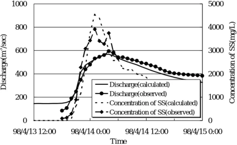
Figures 10 and 11 compare the observed values of discharge and suspended solids with the calculation results. The observation sites were Eiwa Bridge (26.0 km from the river mouth) and Mukawa Bridge. Although the calculated values for discharge tended to be slightly smaller at both sites during the recession stage of flood, the calculated values for rising time of flood and peak discharge were close to the measurement values. The calculated and observed peaks for suspended solids concentration and for waveform at Mukawa Bridge were close; however, the calculated peaks lagged behind the observed peaks.
The result was that the phenomena associated with the longitudinal transport of suspended solids were not satisfactorily reproduced by the calculation. At Eiwa Bridge, observations of suspended solids were not made, so comparison could not be drawn.
(3) Model that considers exchange between suspended solids and riverbank material
Based on the observations of the suspended solids concentration in the flowing water during the flood in the Mukawa River basin, we assumed, concerning the diffusion phenomenon in the cross-sectional direction, that in the early stage of the rising of flood, the suspended solids of 0.01 to 0.1 mm were supplied near the riverbanks before moving to the centerline of flow and then from the centerline of flow back to the riverbanks12). In addition, measurements of the scouring and deposition of the riverbank sediments showed that
0 200 400 600 800 1000
98/4/13 12:00 98/4/14 0:00 98/4/14 12:00 98/4/15 0:00 Time
Discharge(m3 /sec)
0 1000 2000 3000 4000 5000
Concentration of SS(mg/L)
Discharge(calculated) Discharge(observed)
Concentration of SS(calculated) Concentration of SS(observed)
Figure 11 Calculation results at Mukawa Bridge
exchanges between the suspended solids and the riverbank sediment took place during the flood. This was considered to be so, given that riverbank sediment of less than 0.1 mm (the observed grain size
of the suspended solids) made up about 10% of the scour and deposition12).
In light of the results above, we examined a one-dimensional unsteady flow model for transport process of suspended solids, into which was incorporated the exchange of very fine sand for riverbank sediments. Because this was a one-dimensional calculation for an actual river, a very simple model was used to express the exchange of suspended solids between the water and the riverbed. Furthermore, in view of the extremely low value of suspended solids concentration under normal circumstances, it was assumed that floatation and sedimentation of very fine sand at the banks exert influence when the water level exceeds that at the outset of calculation.
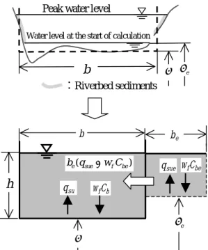
We assumed the following: There is a hypothetical floodplain whose initial water level equals the floodplain height (η). When flowing water spreads over the floodplain, erosion of very fine sand occurs due to tractive force. At any cross section, the suspended solids concentration for the river channel equals that for the hypothetical floodplain, and that determines the amounts of floatation and sedimentation of sand particles. The width of the hypothetical floodplain is set according to differences between the river widths at the initial water level and at the peak water level. The hypothetical floodplain is not included in the passage section of flowing water in the unsteady flow calculation, owing to the need to consider two factors: (1) the floodplain is near the riverbanks, and (2) distribution discharge in the whole section is small during floods. Figure 12 diagrams the method of determining cross sections, including that of the hypothetical floodplain, for calculation.
To make calculations based on the above, the continuity equation of suspended solids concentration by grain size (equation (6)) was transformed into equation (13).
( ) ( ) ( ) ( sui fi bi) (
e suei fi bei)
i i
i bq w C b q w C
x hb C x x
C hb uhb
t C + − + −
∂
∂
∂
= ∂
∂ +∂
∂
∂ ε (13)
Figure 12 Model of cross section and supply of suspended solids from riverbed sediments
b η ηe
:Riverbed sediments Water level at the start of calculation
Peak water level
ηe qsue wfCbe
be b
η
h q
su wfCb ) ( sue f be
e q w C
b −
0 20 40 60 80 100
1.E-02 1.E-01 1.E+00 1.E+01 1.E+02
Grain Size(mm)
Percentage Finer(%)
kp2.6 kp11.0 kp23.4 kp33.8 kp40.7
Figure 14 Grain size distribution of riverbed sediments Figure 13 Calculation result at Mukawa Bridge
0 1000 2000 3000 4000 5000
4/13 12:00 4/13 18:00 4/14 0:00 4/14 6:00 4/14 12:00 Time
Concentration of SS(mg/L)
Observed value Calculated value(Model that considers exchange between suspended solids
and riverbank material)
Calculated value(Model that considers don't exchange between suspended
solids and riverbank material)
where, be : width of the hypothetical floodplain, qsue : floatation amount of suspended load from the hypothetical floodplain per unit time unit area, Cbe : suspended solids concentration near the bed of the hypothetical floodplain. i represents the value of a term when grain diameter di is i. The third term on the right-hand side of equation (13) represents inflow and outflow of suspended solids.
Figure 13 shows the results for calculation that took into account the exchange of very fine sand between the riverbank sediments and the suspended solids using the hypothetical floodplain. It also shows the observed values for Mukawa Bridge. To investigate the riverbank sediments, the grain size distribution of bed materials present in the hypothetical floodplain was set such that the distribution would vary longitudinally, by interpolation of the values obtained at each point12). The investigation was conducted at three cross sections about every 10 km in the river section studied. Figure 14 shows the grain size distributions of the riverbank sediments at each investigation point. In the calculations, the rising time of suspended solids concentration was close to the observed values, but the peak value of concentration was somewhat larger than the observed value. This can be attributed to the following: Actual observation shows that the concentrations of the suspended material in the water channel differ between channel and floodplain. Therefore, when the water level rises, the concentration of suspended solids in the water over the floodplain is higher than in the channel, which reduces the upflow of sand particles from the riverbed. This model did not take into consideration this phenomena. To simplify the calculation, suspended solids concentrations were assumed to be equal between the hypothetical floodplain and the river channel. In future, it will be important to consider how to factor in the diffusion due to differences in concentration in the transverse direction.
This model was able to calculate the time when initial state of suspended material concentration rises. It suggests that it is necessary to take into consideration the exchange of riverbank sediments when examining the transport of suspended solids in the longitudinal direction during flood.
4. CONCLUSION
To verify the longitudinal transport process of suspended solids, one-dimensional unsteady-flow calculation of riverbed evolution was made based on the observation of flood in the Mukawa River. The results showed that if suspended solids are considered as wash load that flows down without exchanging with bed materials, then the calculated rise in concentration occurs later than the observed value. By applying a simple model in which suspended solids flow as they exchanges with the riverbank sediments, calculations could describe the observed phenomenon whereby the suspended solids concentration peaks earlier than the discharge.
In determining the height and width of the hypothetical floodplain, we must ensure that the calculated peak concentration agrees with the observed peak concentration. Although this process involves some uncertainty, the calculations of this study agree with past investigation results, which suggests that the riverbank sediments affected suspended solids concentration during flood and caused the changes in concentration.
REFERENCES
[1] Y., Watanabe, R., Sinme, D., Saito and T., Tamagawa. Field observation of mass- transfer during the 1998 snowmelt flood in the Mukawa River. Annual Journal of Hydraulic Engineering, Japan Society of Civil Engineers, vol.43, 587-592, 1999. (In Japanese)
[2] H., Miyake and Y., Watanabe. Study on supply process of suspended solids to flood flow. Proceedings of Hokkaido chapter of the Japan society of civil engineers, No.56 (B), 132-138, 2000. (In Japanese)
[3] Y., Kurashige. Recent studies on suspended sediment in river. Geophysical bulletin of Hokkaido University, No.59, 1-13, 1996. (In Japanese)
[4] T., Yabe, M., Miyama and S., Kabashima. Simulation physics by the personal computer. Asakura bookstore, 41-47, 1992. (In Japanese)
[5] Y., Shimizu. A study on prediction of flows and bed deformations in alluvial streams.
Report of the civil engineering research institute, No.93, 1991. (In Japanese)
[6] Y., Shimizu. Longitudinal profile of bed elevation and grain size in alluvial rivers.
Journal of hydraulic, coastal and environmental engineering, Japan society of civil engineers, No.521, 69-78, 1995. (In Japanese)
[7] K., Ashida and M., Michiue. Studies on bed load transportation for nonuniform sediment and river bed variation. Disaster prevention research institute annuals, Kyoto University, No.14B, 1971. (In Japanese)
[8] H., Asada. Study on the Sediment Transport of Mountain Rivers and the Sedimentation Process of Reservoirs. Annual Research Report, Central Research Institute of Electric Power Industry, No.2, 1976. (In Japanese)
[9] Y., Iwagaki. Hydrodynamical study on critical tractive force. Transactions of the Japan society of civil engineers, No.41, 1956. (In Japanese)
[10] T., Itakura and T., Kishi. Open Channel Flow with Suspended Sediments. Jour.
Hyd. Div., Proc. ASCE, Vol. 106, No. HY8, 1980.
[11] K., Oki and M., Kuroki. Examination of Calculation Method of Sediment Transport Amount on Riverbed with Sediment Mixture. Proceedings of the 40th annual conference of the Japan society of civil engineers, 2, 415-416, 1985. (In Japanese)
[12] Y., Watanabe, K., Hasegawa and N., Hashimoto. Lateral diffusion of suspended solids and scouring and deposition of fine sand on the floodplain during floods.
Annual Journal of Hydraulic Engineering, Japan Society of Civil Engineers, vol.44, 413-418, 2000. (In Japanese)