SPS SPS SPS
SPS
1.
1.1.
1.
(Spark Plasma Sintering : SPS)
1),2)
MA
Ni-Cu-Zn MA
SPS
3)
Ni-Cu-Zn
SPS SPS
2.
2.2.
2.
2.12.12.1
2.1
Table 1Table 1Table 1Table 1 SPS MA MA
99.91 % 275.9 µm Ni-Cu
matrix
4 30 Ferrite
12 MGFR 14 MGFR 18 MGFR
10 Ferrite
Pure Al 34 MGFR
38 MGFR 32 MGFR
52 MGFR
8 2 4 8 2 8 compound
58 MGFR
Designation Material (mass%) MA time (h)
54 MGFR 50 Ferrite
2 4
-Zn ( (Fe2O3)49.41
(ZnO)32.09(NiO)12.71(CuO)5.79
4.3 µm) Table 1Table 1Table 1Table 1
( CH3(CH2)16COOH)
0.75 g MA
MA Fig.
Fig. Fig.
Fig. 1111 SPS
50 mm 20.1 mm 40 mm
20 mm 20 mm
MA 5 g
Fig. 1 Fig. 1 Fig. 1 Fig. 1
473 K
SPS 2.2
2.22.2
2.2
SPS
1 kg
20 7
5
SPS X
Table 1 Table 1 Table 1
Table 1 Designation, starting compositions Designation, starting compositions Designation, starting compositions Designation, starting compositions and mechanical alloying time of test and mechanical alloying time of test and mechanical alloying time of test and mechanical alloying time of test materials.
materials.
materials.
materials.
Properties of Magnesium Based Composites Exhibiting Magnetism by Spark Plasma Sintering.
Sho AOKI, Hiroki MATSUSHIMA, Kiyozumi NIIZUMA and Masahiro KUBOTA
−日本大学生産工学部第42回学術講演会(2009-12-5)−
― 105 ― 1-30
Starting powders Mechanical alloying (MA)
MA powders
Spark Plasma Sintering (SPS)
SPS materials
MA time : 2,4,8 h
Temp : 673 K~873 K Holding time : 1 h Pressure : 49 MPa Heating rate : 1.67 K/s
40 kV 60 mA CuKα
1.66×10⁻² °/s 2θ 20° 80°
SPS ( )
(Vibrating Sample Magnetometet : VSM)
6×4×1 mm 800 kA/m
SPS SPS
(
3 g 20 ml
20 ml 2 ml)
3.
3.3.
3.
Fig. 2 Fig. 2Fig. 2
Fig. 2 SPS
14
MGFR SPS
673 K SPS
Ni-Cu-Zn Mg
MgO α-Fe
773 K 873 K SPS
Mg MgO α-Fe Mg2Ni Fe3C
MgO MgO Ni-Cu-Zn
MgO Fe2O3
1mol
Fig. 3 Fig. 3 Fig. 3 Fig. 3
MgO Fe2O3
●
●
●
●
●●
●●
●
●●
●
●
●
●
●
●●
●●
●
●●
●●●●● ●●●● ■■■■
▲▲
▲▲
■■■
■
■
■■
■
●
●
●
●
●
●●
●
◆◆
◆◆
◆
◆
◆
◆
●
●
●
● MgMgMgMg
▲
▲
▲
▲ FeFeFeFe
■■
■■:MgO:MgO:MgO:MgO
◆
◆
◆
◆ MgMgMgMg2222NiNiNiNi
★★
★★ FeFeFeFe3333CCCC
▼
▼
▼
▼ NiNiNiNi----CuCuCuCu----Zn FerriteZn FerriteZn FerriteZn Ferrite
Intensity(arb. units)Intensity(arb. units)Intensity(arb. units)Intensity(arb. units)
Diffraction angle, 2 Diffraction angle, 2 Diffraction angle, 2 Diffraction angle, 2θθθθ deg) deg) deg) deg)
MgMg
MgMg----10mass%Ferrite10mass%Ferrite10mass%Ferrite10mass%Ferrite SPS materials SPS materials SPS materials SPS materials fabricated from MA4h powder fabricated from MA4h powder fabricated from MA4h powder fabricated from MA4h powder
(a)(a)(a) (a) (c) (c) (c) (c)(b) (b) (b)(b)
(a) powder (a) powder(a) powder (a) powder (b) (b) (b) (b) 673 K673 K673 K673 K (c) (c) (c) (c) 773 K773 K773 K773 K (d) (d)(d) (d)873 K873 K873 K873 K
(d) (d)(d) (d)
▼▼▼
▼ ▼▼▼▼ ■■■■ ▲▲▲▲ ▼▼▼▼ ●●●●
●
●
●
●
●●
●●
●
●●
● ●●●●
■■■
■ ■■■■
●
●
●
● ●
●●
●
★
★
★
★ ★★★★ ★★★★ ★★★★ ★★★★
★★
★★
★
★
★
★
-1.0 -0.8 -0.6 -0.4 -0.2 0.0
1000 1100 500 600 700 800 900
400 300 Standard free energy of formation, ⊿G / MJ/molO
Temperature, T / K
1/3 Fe2O3 MgO
Fe 2 MgO 3 O Fe Mg
3 +
2 3→ +
(1)Ni-Cu-Zn Fe2O3
MgO α-Fe 773 K
873 K α-Fe
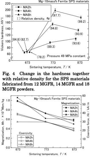
Fe3C Fig. 4
Fig. 4Fig. 4
Fig. 4 MA SPS
12 MGFR 673 K
SPS 65.0 HV
673 K
84.8%
773 K 873
K Ni-Cu-Zn
(MgO α-Fe Mg2Ni Fe3C) Fig. 3 The standard free energies of Fig. 3 The standard free energies of Fig. 3 The standard free energies of Fig. 3 The standard free energies of formation of the relevant oxides as a formation of the relevant oxides as a formation of the relevant oxides as a formation of the relevant oxides as a function of temperature.
function of temperature.function of temperature.
function of temperature.
Fig. 2 Fig. 2 Fig. 2
Fig. 2 XXXX----rrrray diffraction patterns of ay diffraction patterns of ay diffraction patterns of ay diffraction patterns of SPS SPS SPS SPS materials fabricated
materials fabricatedmaterials fabricated
materials fabricated from 14 MGFR from 14 MGFR from 14 MGFR from 14 MGFR powder.
powder.powder.
powder.
Fig. 1 Process chart for fabricating test Fig. 1 Process chart for fabricating test Fig. 1 Process chart for fabricating test Fig. 1 Process chart for fabricating test materials.
materials.materials.
materials.
― 106 ―
14 MGFR 18 MGFR
773 K SPS
154.7 HV 198.0 HV 873 K
135.8 HV 175.8 HV 773 K
Fig. 2 Fig. 2 Fig. 2 Fig. 2 X MgO
MgO Fe3C Mg2Ni
Fe3C 1200 HV4)
873 K
773 K MA
MA 2
4 8 h 96.6 HV 154.7 HV
198.0 HV MA
50 HV MA
MA SPS 773 K
Fig. 5 Fig. 5Fig. 5
Fig. 5 MA SPS
MA 673
K SPS
1.0×10⁻⁵ Wbm/kg MA (0.65×10⁻⁵ Wbm/kg) 2
MA α-Fe
α-Fe 2.73×10⁻⁴
Wbm/kg Ni-Cu-Zn
Fe2O3 50 %
Mg-10 mass% Ferrite 5 % Fe2O3
Fe2O3 α-Fe
69.94 % Mg-10 mass%
Ferrite 3.5 % α-Fe α-Fe
3.5 % 0.95×10⁻⁵ Wbm/kg SPS
0 60 80 100 120 140 160 180 200 220
Sintering temperature, T / K
Mg-10mass% Ferrite SPS materials
(99.2)
(93.9) (97.7)
(78.2) (94.8)
(82.7)
(93.6)
873 773
673 (84.8)
(89.3)
Pressure 49 MPa constant
Vickers hardness, HV 1
MA2h MA4h MA8h
( ) Relative density,
0.0 0.2 0.4 0.6 0.8 1.0
0 10 20 30 40 50 60
873 773
673
Coercive force, Hc / kA/m
Coercivity
Magnetization
Magnetization, Ms / ×10-5Wbm/kg
Sintering temperature, T / K MA2h MA4h MA8h Mg-10mass% Ferrite SPS materials
MA2h MA4h MA8h
0.95×10⁻⁵ Wbm/kg Ni-Cu-Zn Fe2O3 α-Fe
MA SPS Fig.
Fig.
Fig.
Fig. 2222 X Ni-Cu-Zn
Fe3C
Fe3C α
-Fe Fe3C
MA SPS
α-Fe Fe3C Fig. 5
Fig. 5 Fig. 5
Fig. 5 Change in the Change in the Change in the magneChange in the magnemagnemagnetizationtizationtization and tization and and and coercive force for the SPS materials coercive force for the SPS materials coercive force for the SPS materials coercive force for the SPS materials fabricat
fabricatfabricat
fabricatededed from edfrom from 12 MGFR, 14 MGFR and 18 from 12 MGFR, 14 MGFR and 18 12 MGFR, 14 MGFR and 18 12 MGFR, 14 MGFR and 18 MGFRMGFRMGFR
MGFR powderpowderpowders.powders.s.s.
Fig. 4 Fig. 4 Fig. 4
Fig. 4 Change in the hardnessChange in the hardnessChange in the hardnessChange in the hardness together together together together with relative density
with relative densitywith relative density
with relative density for the SPS materials for the SPS materials for the SPS materials for the SPS materials fabricat
fabricatfabricat
fabricatededed from edfrom from 12 MGFR, 14 MGFR and 18 from 12 MGFR, 14 MGFR and 18 12 MGFR, 14 MGFR and 18 12 MGFR, 14 MGFR and 18 MGFR
MGFR MGFR
MGFR powderpowderpowderssss.... powder
― 107 ―
Fig. 6 Fig. 6Fig. 6
Fig. 6 14 MGFR
(a) 673 K (b) 883 K (c) 873 K SPS
Fe3C
Fe3C
Mg MA
Fe3C Fe3C
673 K 10~30 µm
773 K 10~60 µm
873 K 20~100 µm
873K SPS
Fe3C
10μ (a)
10μ (b)
4.4.4.
4.
Ni-Cu-Zn MA
SPS SPS
1) 673 K SPS
MgO α-Fe
773 K 873 K
SPS MgO α-Fe
Mg2Ni Fe3C
2) MA 8 h 773
K
Fe3C
198.0 HV
3) 673 K SPS
Ni-Cu-Zn Fe2O3
α-Fe
MA 2
773 K 873 K
Fe3C α-Fe
SPS 4) SPS
α-Fe
5) Fe3C
SPS 873 K 773 K
6) Ni-Cu-Zn
673 K
4
1) ―
(SPS) , SPS pp.1-4.
2) 30 (1993)
pp.790-802 3)
116
(2009) pp.103-104
4) http://www.tobu.or.jp/yasashii/book/gj0 6.htm
10μ (c)
Fig.
Fig.
Fig.
Fig. 6666 Optical micrographs of the SPS Optical micrographs of the SPS Optical micrographs of the SPS Optical micrographs of the SPS materials
materials materials
materials fabricated from 14 MGFR powderfabricated from 14 MGFR powderfabricated from 14 MGFR powder fabricated from 14 MGFR powder at different temperatures of (a) 673 K, at different temperatures of (a) 673 K, at different temperatures of (a) 673 K, at different temperatures of (a) 673 K, (b) (b) (b) (b) 773 K and (c) 873 K.
773 K and (c) 873 K.
773 K and (c) 873 K.
773 K and (c) 873 K.
― 108 ―