Mitsuteru YOSHIDA†a), Kei SAKAGUCHI†b),Members,andKiyomichi ARAKI†c),Fellow
SUMMARY In recent years, wireless communication technology has been studied intensively. In particular, MIMO which employs several transmit and receive antennas is a key technology for enhancing spec- tral efficiency. However, conventional MIMO architectures require some transceiver circuits for the sake of transmitting and receiving separate sig- nals, which incurs the cost of one RF front-end per antenna. In addition to that, MIMO systems are assumed to be used in low spatial correlation en- vironment between antennas. Since a short distance between each antenna causes high spatial correlation and coupling effect, it is difficult to miniatur- ize wireless terminals for mobile use. This paper shows a novel architecture which enables mobile terminals to be miniaturized and to work with a sin- gle RF front-end by means of adaptive analog beam-forming with parasitic antenna elements and antenna switching for spatial multiplexing. Further- more, statistical analysis of the proposed architecture is also discussed in this paper.
key words: single front-end architecture, parasitic antenna elements, MIMO, equal gain combining
1. Introduction
Conventional MIMO architectures need a transceiver cir- cuit for each antenna, which means that multiple antenna systems increase power consumption and size of RF front- end circuit. Hence, a single RF front-end architecture is an ideal one to overcome this problem. Some techniques re- alizing MIMO with a single RF front-end circuit have been proposed. One such technique is to use parasitic antenna elements. The elements are not supplied with power and only reflect incident radio waves [1]. The single RF front- end MIMO can be realized when the value of variable re- actances connecting to parasitic antenna elements are con- trolled properly so as to generate orthogonal directivity pat- terns, because each orthogonal directivity pattern is spatially independent and can receive spatial distinct signals [2]. An- other technique for realizing MIMO with a single RF front- end is antenna switching method based on sampling theo- rem for band-limited signal [3]. In [4], spatial multiplex- ing with phase state preserved can be realized using antenna switching. If the phase of signals is obtained in addition to its’ amplitude, a diversity combining technique of mul- tiple antenna systems can be operated effectively in digital signal processing (DSP) stages. However, both techniques
Manuscript received April 18, 2011.
Manuscript revised August 17, 2011.
†The authors are with the Tokyo Institute of Technology, To- kyo, 152-8550 Japan.
a) E-mail: [email protected] b) E-mail: [email protected] c) E-mail: [email protected]
DOI: 10.1587/transcom.E95.B.882
decrease the SNR because these processes cause aliasing and interference effect from other channels against desired signals. In order to avoid undesired effects, the rotation speed of antenna directivity or the antenna switching rate must be higher than signal bandwidth. Furthermore, chan- nel selection filters are needed in front of these processes [5]. The problem common to both methods is deterioration in quality of the SNR. Beam-forming techniques in digi- tal or analog dimension are well known as the method to improve the SNR by steering a directivity to desired sig- nals. Adaptive analog beam-forming systems using para- sitic antenna elements are called ESPAR antenna systems [6]. Of course, ESPAR systems with a single RF front-end can also achieve spatial multiplexing [7]. In contrast, to the best of our knowledge, few papers discuss the compatibility between antenna switching and analog beam-forming. This paper proposes a novel single RF front-end MIMO architec- ture which takes advantage of not only antenna switching for spatial multiplexing but also adaptive analog beam-forming by parasitic antenna elements for compensating the switch- ing penalty. Although the proposed architecture necessitates antenna switching frequency higher than signal bandwidth, the operating frequency of steering directivity by parasitic antenna elements can be reduced down to the fading rate known as Doppler spread that characterizes the time vari- ation of the channel; therefore, while the change of beams within the symbol period expands the signal bandwidth, the effect in the proposed architecture is negligible because the directivity pattern to the direction of arrival wave by para- sitic antenna elements has not been changed during the sym- bol time.
2. SNR Penalty on Antenna Switching for Spatial Mul- tiplexing
In wireless communication system where signals’ band- width is limited, the Sampling theorem states that signals have redundancy in time domain. The received RF sig- nal, sm(t), at m-th antenna with spectrum, Sm(f) = 0 in
|f −fc|> B/2 where fcis carrier frequency, can be recov- ered when the signal is sampled in a time period shorter than 1/B, even though the SNR of switched signal deteriorates.
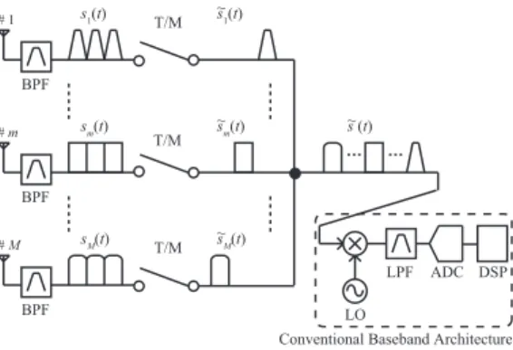
Now, consider the system which consists of Manten- nas in Fig. 1 where the band-limited RF signal impinges at each antenna and passed through a band pass filter (BPF) which is needed for anti-aliasing caused by switching oper- ation at next stage, but not for selecting channels. Channel Copyright c2012 The Institute of Electronics, Information and Communication Engineers
Fig. 1 Antenna switching operation.
selection is performed at the baseband by DSP. Then, the RF signal is sampled and holded duringT/Mtime period.
The switched signal, ˜sm(t), atm-th antenna is expressed as the product ofsm(t) andum(t) defined by Eq. (1) in the form of Fourier series.
um(t) ∞
n=−∞
M
T
t−m−1 M T−nT
= 1 M
∞ n=−∞
sin (πn/M)
πn/M ej2πnT(t−mM−1T), (1) where
(x)=⎧⎪⎪⎨
⎪⎪⎩1 ifx∈ −12,12
0 ifx −12,12 (2)
Then, the SNR of switched and sampled signal is derived as follows. Wiener-Khinchin theorem states that power spectrum density (PSD) is the Fourier transform of auto-correlation function. s˜m(t) has the auto-correlation function, ˜Am(τ), as Eq. (3) because sm(t) has the auto- correlation function, Am(τ) = E[sm(t)sm(t+τ)], if sm(t) is wide sense stationary. Note thatE[·] denotes expectation operator.
A˜m(τ,t) = E[ ˜sm(t) ˜sm(t+τ)]
= Am(τ) M2
∞ n=−∞
sin2(πn/M)
(πn/M)2 e−j2πTnτ (3) According to Wiener-Khinchin theorem, ˜Sm(f) is of the form shown in Eq. (4). Note thatF[·] denotes Fourier transform operator.
S˜m(f) =F A˜m(τ)
= 1 M2
∞ n=−∞
sin2(πn/M) (πn/M)2
×
∞
−∞Am(τ)e−j2πTnτe−j2πfτdτ
= 1 M2
∞ n=−∞
sin2(πn/M) (πn/M)2 Sm
f+ n
T
(4) Furthermore, a PSD of switched white noise, ˜N(f), is
Fig. 2 Equivalent MIMO channel.
of the form in Eq. (5), provided that the white noise has a constant PSD, N0/2, before switching. Note that B2(x) is the Bernoulli polynomial of second degree.
N(˜ f) = 1 M2
∞ n=−∞
sin2(πn/M) (πn/M)2
N0
2
= 1 M2
⎧⎪⎪⎨⎪⎪⎩1+M2 π2
∞ n=1
1
n2 −M2B2 1
M
⎫⎪⎪⎬⎪⎪⎭N0 2
= 1 M
N0
2 ∴N(˜ f)=N(f)
M (5)
Assuming thatsm(t) is band-limited in|f −fc| ≤ B/2 and switching period for m-th antenna, T, is shorter than 1/B, then the switching operation does not cause aliasing.
Therefore, the signal can be recovered according to the Sampling theorem. However, the SNR of switched signal through the BPF whose bandwidth equalsBis deteriorated by 10 logM[dB] from Eq. (6) whereγis the average branch SNR before switching.
fc+B/2
fc−B/2 S˜m(f)d f fc+B/2
fc−B/2 N(˜ f)d f = fc+B/2
fc−B/2 1
M2Sm(f)d f fc+B/2
fc−B/2 1
MN(f)d f = γ
M (6)
From above discussion, equivalent MIMO channel in Fig. 2, ˜H, affected by switching operation is expressed as Eq. (7) whereHandhl are a conventional MIMO channel and aM×1 conventional channel vector respectively.
H˜ =
1
√Mh1,· · ·, 1
√Mhl,· · ·, 1
√MhL
= 1
√MH (7)
3. Statistical Analysis of Parasitic Antenna Element System
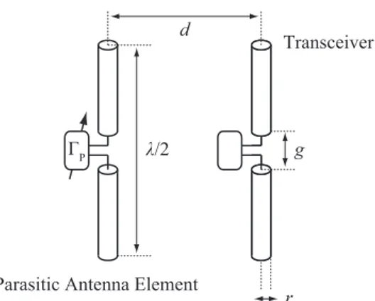
In previous section, it has been shown that antenna switch- ing architecture can realize spatial multiplexing at the ex- pense of performance degradation as compared to conven- tional MIMO architecture, and the SNR penalty of switch- ing process is evaluated theoretically. In order to overcome this penalty, we apply an adaptive beam-forming with para- sitic antenna elements to our architecture. Parasitic antenna elements (PAEs) are connected not to the RF front-end but to the variable reactance. Re-radiation effect of these elements enable us to steer the directivity adaptively by changing the value of reactances. In the switching process for spatial mul- tiplexing, the single RF front-end is connected to only one
Fig. 3 Parasitic antenna element system.
antenna, whereas the other antennas are terminated in open or connected to dummy loads. At this, if these unconnected antennas are tapped to variable reactances and deployed as PAEs, the PAEs contribute to improve the SNR. This section shows that this proposed operation is sufficient for compen- sating the penalty of SNR and its average error probability is the same stochastic characteristic of Equal Gain Combining (EGC) in digital signal processing.
Now, consider a system which consists of one transmit antenna, one receive antenna and one PAE. Since PAE and usual antenna exchange the their roles as whether receive antenna or PAE periodically in antenna switching frequency, the state fixed in a period is equivalent to Fig. 3. Analysis of this system leads us to obtain statistical characteristics of the proposed architecture. First, let us define a scattering matrix of free space and a reflection coefficient of the reactance value connected to the PAE asSandΓPrespectively. Then, a scattering matrix of free space including parasitic antenna elements, ˜S, is expressed by Eq. (9) [8].
S
⎡⎢⎢⎢⎢⎢
⎢⎢⎣
STT STR STP
SRT SRR SRP
SPT SPR SPP
⎤⎥⎥⎥⎥⎥
⎥⎥⎦ (8)
S˜
S˜TT S˜TR
S˜RT S˜RR
⇔
⎧⎪⎪⎪⎪⎪⎪⎪
⎨⎪⎪⎪⎪⎪
⎪⎪⎩
S˜TT=STT+STP(Γ−1P −SPP)−1SPT
S˜TR=STR+STP(Γ−1P −SPP)−1SPR
S˜RT=SRT+SRP(Γ−1P −SPP)−1SPT
S˜RR=SRR+SRP(Γ−1P −SPP)−1SPR
(9)
Therefore, the spectral efficiency in this model is for- mulated by Eq. (10) whereγis average branch SNR, pro- vided|ΓP| ≤1 holds: the PAE are passive.
C/B = E
|ΓmaxP|≤1log
1+γS˜RT2
= E
log
1+γmax
|ΓP|≤1S˜RT2
(10) From Eq. (10), maximization problem on the spectral efficiency results in another maximization problem on the
W max
|ΓP|≤1S˜RT
=
SRT+S∗PPSRPSPT
1− |SPP|2
+ |SRPSPT|
1− |SPP|2 (11) ΓoptP = argmax
|ΓP|≤1
log
1+γS˜RT2
=argmax
|ΓP|≤1
S˜RT
=
SRPSPTS∗PP
|SRPSPT| + (1−|SPP|2)SRT+SRPSPTS∗PP
|(1−|SPP|2)SRT+SRPSPTS∗PP|
SRPSPT
|SRPSPT|+(1−|SPP|2)SRTSPP+SRPSPT|SPP|2
|(1−|SPP|2)SRT+SRPSPTS∗PP|
(12) IfSRTandSPTare correlated random variables and fol- low a complex Gaussian distribution,CN
0, σ2S
,XandY which are defined by Eq. (13) are Rayleigh random variables correlated to each other.
⎧⎪⎪⎨
⎪⎪⎩XSRT+S1∗PP−|SSRPSPT
PP|2 Y |1−|SRPSSPT|
PP|2
(13) LetpW(w) be the probability density function (PDF) of W, and then it is of the form of Eq. (14) with joint PDF, pX,Y(x, y).
pW(w)=
∞
−∞
∞
−∞
δ(w−x−y)pX,Y(x, y)dxdy (14) Although it is difficult to obtain pW(w) in closed form [9], the average error probability of BPSK modulation in this model can be obtained becauseW consists of the sum of two Rayleigh random variables [10]. It means that this system has the same statistical characteristic as EGC which is a kind of diversity combiner.
When the random variables,w = [wX, wY]T, follow a multivariate complex gaussian distribution, joint PDF,p(w), is written as Eq. (15) subject toE[w]=0[11].
p(w)= 1
π2|detΨ|exp
−w†Ψ−1w
(15) Ψ =E ww†
σ2X σXσYζ σXσYζ∗ σ2Y
The absolute value of random variables,X =|wX|and Y =|wY|, have the joint PDF,pX,Y(x, y), which is written as Eq. (16).
pX,Y(x, y) = 4xy σ2Xσ2Y
1− |ζ|2
×exp
⎛⎜⎜⎜⎜⎜
⎜⎝− σ2Yx2+σ2Xy2 σ2Xσ2Y
1− |ζ|2
⎞⎟⎟⎟⎟⎟
⎟⎠
×I0
⎛⎜⎜⎜⎜⎜
⎜⎝ 2xy|ζ| σXσY
1− |ζ|2
⎞⎟⎟⎟⎟⎟
⎟⎠ (16)
Therefore, the characteristic function of this joint PDF, φW(ξ), is expressed by Eq. (17) whereΓ(x) is the gamma function and 1F1(a;b;x) is the Kummer’s function of the first kind [12].
φW(ξ) =
1− |ζ|2∞
n=0
⎡⎢⎢⎢⎢⎢
⎣ |ζ|n
n!
2
L0,n
ξ;|ζ|2;σ2X
×L0,n
ξ;|ζ|2;σ2Y⎤
⎥⎥⎥⎥⎥
⎦, (17)
where L0,n
ξ;|ζ|2;σ2
Γ(n+1)
×1F1
⎛⎜⎜⎜⎜⎜
⎜⎝n+1;1 2;−σ2
1− |ζ|2
4 ξ2
⎞⎟⎟⎟⎟⎟
⎟⎠
+jξ σ2
1− |ζ|212 Γ
n+3
2
×1F1
⎛⎜⎜⎜⎜⎜
⎜⎝n+3 2;3
2;−σ2 1− |ζ|2
4 ξ2
⎞⎟⎟⎟⎟⎟
⎟⎠
Since the statistical characteristic in this model does not depend on any modulation formats, for the simplicity in analysis, we assume that the transmitted signal,s, is modu- lated by BPSK. Then, the received signal,r, after coherent detection in PAE system is expressed by Eq. (18). Note that an additive noise,z, followsCN
0, σ2N
, and[·] denotes the real part of a complex number.
r =(X+Y)s+[z]=W s+nI (18) Therefore, the average error probability,Pe, of BPSK modulation in coherent detection equals Pr(0) because Eq. (19) holds wherePr(r) is cumulative distribution func- tion of received signal.
Pe=⎧⎪⎪⎨
⎪⎪⎩Probability inr<0 wheres=1
Probability inr>0 wheres=−1 (19) φnI(ξ) is the characteristic function of In-phase component of noise and is expressed by exp
−12σ22Nξ2
. Provided thatnI
is random variable independent ofWands, the characteris- tic function ofr,φr(ξ), is the product ofφW(ξ) andφnI(ξ) which are characteristic functions ofWandnIrespectively.
Therefore,φr(ξ) is written as Eq. (20).
φr(ξ) =
1− |ζ|2∞
n=0
⎡⎢⎢⎢⎢⎢
⎣ |ζ|n
n!
2
L0,n
ξ;|ζ|2;σ2X
×L0,n
ξ;|ζ|2;σ2Y⎤
⎥⎥⎥⎥⎥
⎦×e−14σ2Nξ2 (20) According to Gil-Pelaez’s inversion formula [13], cu- mulative distribution function and characteristic function have a relationship shown in Eq. (21). Note that[·] de- notes the imaginary part of a complex number.
Pr(0)=1 2 −1
π
∞
0
#φr(ξ)$
ξ dξ (21)
Thus, the average error probability is obtained as Eq. (22) from Eq. (20) and Eq. (21). Note that2F1(a,b;c;x) denotes the Gauss’ hypergeometric function.
Pe=Pr(0)= 1
2−1− |ζ|2 2
∞ n=0
2n n
|ζ| 2
2n
× n k=0
n k
(−1)k2n+1 2k+1
×
⎡⎢⎢⎢⎢⎢
⎢⎢⎢⎢⎢
⎢⎣
⎧⎪⎪⎪⎪⎨
⎪⎪⎪⎪⎩ σ2Y
σ2N
1−|ζ|2 +σ2X+σ2Y
⎫⎪⎪⎪⎪⎬
⎪⎪⎪⎪⎭
k+12
×2F1
⎛⎜⎜⎜⎜⎜
⎜⎜⎜⎜⎝−n−1 2,k+1
2;1
2; σ2X
σ2N
1−|ζ|2 +σ2X+σ2Y
⎞⎟⎟⎟⎟⎟
⎟⎟⎟⎟⎠
+⎧⎪⎪⎪⎪⎨
⎪⎪⎪⎪⎩ σ2X
σ2N
1−|ζ|2+σ2X+σ2Y
⎫⎪⎪⎪⎪⎬
⎪⎪⎪⎪⎭
k+12
×2F1
⎛⎜⎜⎜⎜⎜
⎜⎜⎜⎜⎝−n−1 2,k+1
2;1
2; σ2Y
σ2N
1−|ζ|2+σ2X+σ2Y
⎞⎟⎟⎟⎟⎟
⎟⎟⎟⎟⎠
⎤⎥⎥⎥⎥⎥
⎥⎥⎥⎥⎦ (22) Givenσ2X,σ2Y andζ, theoretical curves can be drawn.
These parameters of the system now considered are summa- rized in Eq. (23) where a correlation coefficient,ρ, is defined asE SRTS∗PT
/σ2S. Equation (23) shows thatρis modified bySRPandSPP,ζ, therefore, indicates a modified correla- tion coefficient in this model.
⎧⎪⎪⎪⎪⎪⎪⎪
⎪⎪⎪⎨⎪⎪⎪⎪⎪
⎪⎪⎪⎪⎪
⎩ σ2X=
1+1S−|∗PPSSPPRP|22+2% ρSPPS∗RP
1−|SPP|2
&
σ2S σ2Y =
|SRP| 1−|SPP|2
2
σ2S ζ =
ρ S∗RP
1−|SPP|2+ SPP∗|SRP|2
(1−|SPP|2)2
σXσY σ2S
(23)
The squared absolute value of ρ coincides with the envelope correlation [14] or the power correlation [15] in our assumption. |ρ|2 is often given by Jakes’ model [16]
or Blanch’s model [17]. Since the Jakes’ model assumes that no mutual coupling between two dipoles exists and the directivity is omni-directional, the Blanch’s model is more appropriate to the PAE case that is a narrow spacing case where the lower correlation coefficient is observed [18].
Figures 4 and 5 show that the results of Monte Carlo sim- ulation are consistent with theoretical curves where average branch SNR,γ, is expressed by σ2S/σ2N andρis given by Eq. (24) as Blanch’s model for symmetric antenna structure.
Furthermore, theoretical curves of two branch Maximum Ratio Combining (MRC) given by Eq. (25) and two branch EGC are also plotted in Figs. 4 and 5 for comparison.
|ρ|2= |2 SPP∗ SRP
|2
'1−'|SPP|2+|SRP|2((2 (24)
Table 1 shows the antenna structure parameter and Ta- ble 2 shows the S parameter of this model calculated by Ansoft HFSS in 3.0 GHz, assuming that antennas consist of perfect electric conductor. Equation (22) states that opti- mal adaptive beam-forming in this system, in spite of only one receiver, has the same stochastic characteristic as two branch EGC. In particular, Fig. 5 shows that performance of PAE system ind = λ/8 is almost the same as that of two branch MRC. From these results it is believed that the adap- tive beam-forming using the PAE is equivalent to the tech- nique co-phasing the signals on each pseudo-branch,wXand
Fig. 4 Average error probability of PAE system whered=λ/4.
Fig. 5 Average error probability of PAE system whered=λ/8.
Table 1 Antenna structure parameters in Fig. 3.
λ[m] g[m] r[m]
0.100 λ/1000 λ/1000
Table 2 S parameters in Fig. 3.
SRP SPP
d=λ/4 −0.00888−j0.258 0.444+j0.281 d=λ/8 0.218−j0.378 0.330+j0.442
4. Performance Evaluation of Proposed Architecture In previous sections, it has been shown that PAE operation can improve the error probability. In the case ofM =2 and d=λ/8, in particular, Sect. 2 shows that the switching effect decreases the SNR by 3 dB and Sect. 3 shows that PAE oper- ation increases the SNR by 3 dB. Therefore, notwithstand- ing a single RF front-end, performance of the transceiver equipped with both switching architecture and PAE opera- tion seems to be the same as that of conventional one. Fig- ure 6 shows our proposed architecture in MIMO case. In this section, performance of the proposed architecture is evalu- ated by computer simulation in terms of spectral efficiency subject to 2×2 MIMO as shown in Fig. 7. In the simula- tion, conventional channel matrix is generated by Kronecker model [20] where the receiving correlation is only consid- ered and given by Blanch’s model.
In this simulation model, equivalent MIMO channel is written as Eq. (26) and the spectral efficiency is calculated by Eq. (27). Note that t[·] denotes transpose operator and
·,·denotes inner product operator.
H˜ = 1
√2
S˜RT1(Γ1) S˜RT2(Γ1) S˜PT1(Γ2) S˜PT2(Γ2)
1
√2 t
h˜1(Γ1)
th˜2(Γ2)
(26) C/B = max
|Γ1|,|Γ2|≤1log det
I+γH˜H˜†
=log max
|Γ1|,|Γ2|≤1
% 1+γ
2
h˜12+h˜22
Fig. 6 SF-MIMO w/PAE: Single Front-end MIMO with Parasitic Antenna Element.
Fig. 7 Simulation model.
Fig. 8 Spectral efficiency of proposed architecture whered=λ/4.
Fig. 9 Spectral efficiency of proposed architecture whered=λ/8.
+γ 2
2h˜12h˜22−*
h˜1,h˜2+2
(27) According to Eq. (27), this maximization problem is a combinatorial optimization because there is the term
*h˜1,h˜2+
in this equation. A full search algorithm with 1 degree step size is used in order to find the optimal reflec- tion coefficients,Γopt1 andΓopt2 . Results of this simulation are shown in Figs. 8 and 9.
While Fig. 8 shows that performance of the proposed architecture is worse than that of conventional one because of insufficient improvement by PAE, Fig. 9 shows that per- formance of the proposed architecture is improved by about 2 to 3 dB as expected and then the switching penalty for spatial multiplexing is compensated. In addition to that, in a case with higher mutual coupling and spatial correlation compared withd =λ/8, we obtained a result that the spec- tral efficiency of the proposed architecture remains but that of the conventional architecture deteriorates. These results confirm that performance of the proposed architecture is tol- erant to high spatial correlation environment while the con- ventional MIMO architecture suffers performance degrada- tion from high spatial correlation environment.
5. Conclusion
A novel architecture that realizes single RF front-end by an- tenna switching for spatial multiplexing and improvement
of SNR by adaptive beam-forming was proposed. Further- more, statistical analysis of the antenna switching system with a parasitic antenna element was discussed theoretically.
It was confirmed that the distribution of improved channel by our proposed architecture is identical to that of the out- put from equal gain combiner. This paper also showed that the results of computer simulation in MIMO case give the performance of proposed architecture withd =λ/8, which is the same as that of conventional one. As a result, this scheme provides compact transceivers.
References
[1] R. Dinger, “Reactively steered adaptive array using microstrip patch elements at 4 GHz,” IEEE Trans. Antennas Propag., vol.32, no.8, pp.848–856, Aug. 1984.
[2] R. Bains and R.R. Muller, “Using parasitic elements for implement- ing the rotating antenna for MIMO receivers,” IEEE Trans. Wirel.
Commun., vol.7, no.11, pp.4522–4533, Nov. 2008.
[3] F. Adachi, T. Hattori, K. Hirade, and T. Kamata, “A periodic switch- ing diversity technique for a digital FM land mobile radio,” IEEE Trans. Veh. Technol., vol.27, no.4, pp.211–219, Nov. 1978.
[4] J.D. Fredrick, Y. Wang, and T. Itoh, “A smart antenna receiver array using a single RF channel and digital beamforming,” IEEE Trans.
Microw. Theory Tech., vol.50, no.12, Dec. 2002.
[5] M. Taromaru and H. Aino, “Fast periodic antenna switching for di- versity and smart antenna: On SNR property and spurious response,”
IEEE Antennas and Propagation Society International Symposium 2006, pp.4553–4556, July 2006.
[6] T. Ohira and K. Gyoda, “Electronically steerable passive array ra- diator antennas for low-cost analog adaptive beamforming,” IEEE International Conference on Phased Array Systems and Technology, pp.101–104, 2000.
[7] A. Kalis, A. Kanatas, and C. Papadias, “A novel approach to MIMO transmission using a single RF front end,” IEEE J. Sel. Areas Com- mun., vol.26, no.6, pp.972–980, Aug. 2008.
[8] N. Honma, K. Nishimori, R. Kudo, Y. Takatori, T. Hiraguri, and M. Mizoguchi, “A stochastic approach to design MIMO antenna with parasitic elements based on propagation characteristics,” IEICE Trans. Commun., vol.E93-B, no.10, pp.2578–2585, Oct. 2010.
[9] D. Brennan, “Linear diversity combining techniques,” Proc. IEEE, vol.91, no.2, pp.331–356, Feb. 2003.
[10] R. Mallik, M. Win, and J. Winters, “Performance of dual-diversity predetection EGC in correlated rayleigh fading with unequal branch snrs,” IEEE Trans. Commun., vol.50, no.7, pp.1041–1044, July 2002.
[11] K.S. Miller, “Complex Gaussian processes,” SIAM Review, vol.11, no.4, pp.544–567, Oct. 1969.
[12] D. Middleton, An Introduction to Statistical Communication The- ory, McGraw-Hill, New York, 1960.
[13] J. Gil-Pelaez, “Note on the inversion theorem,” Biometrika, vol.38, no.3-4, pp.481–482, 1951.
[14] R.G. Vaughan and J.B. Andersen, “Antenna diversity in mobile com- munications,” IEEE Trans. Veh. Technol., vol.36, no.4, pp.149–172, Nov. 1987.
[15] J.R. Mendes and M.D. Yacob, “Power correlation coefficient of a general fading model,” SBMO/IEEE MTT-S International Confer- ence on Microwave and Optoelectronics, pp.497–502, July 2005.
[16] W.C. Jakes and D.C. Cox, eds., Microwave Mobile Communica- tions, Wiley-IEEE Press, 1994.
[17] S. Blanch, J. Romeu, and I. Corbella, “Exact representation of an- tenna system diversity performance from input parameter descrip- tion,” Electron. Lett., vol.39, no.9, pp.705–707, May 2003.
[18] Y. Yamada, K. Kagoshima, and K. Tsunekawa, “Diversity anten- nas for base and mobile stations in land mobile communication sys-
pp.1211–1226, Aug. 2002.
Mitsuteru Yoshida was born in 1985. He received the B.E. and the M.E. degree in elec- trical and electronic engineering from Tokyo In- stitute of Technology, Japan, in 2008 and 2010.
In 2010, he joined the NTT Network Innovation Laboratories, Nippon Telegraph and Telephone Corporation (NTT). This work had done when he was a student at Tokyo Institute of Technol- ogy.
Kei Sakaguchi was born in 1973. He re- ceived the B.E. degree in electrical and com- puter engineering from Nagoya Institute of Technology, Japan, in 1996, and the M.E. degree in information processing from Tokyo Institute of Technology, in 1998, and the Ph.D. degree in electrical and electronic engineering from To- kyo Institute of Technology, in 2006. From 2000 to 2007, he was an Assistant Professor at Tokyo Institute of Technology. Since 2008, he has been an Associate Professor at the same university.
He received the Young Engineer Awards from IEICE and IEEE AP-S Japan chapter in 2001 and 2002 respectively, the Outstanding Paper Awards from SDR Forum and IEICE in 2004 and 2005 respectively, and the Tutorial Paper Award from IEICE communication society in 2006. His current in- terests are MIMO propagation measurements, MIMO communication sys- tems, and software/cognitive radio. He is a member of IEEE.
Kiyomichi Araki was born in 1949. He received the B.S. degree in electrical engineer- ing from Saitama University, Japan, in 1971, and the M.S. and the Ph.D. degrees in physical electronics both from Tokyo Institute of Tech- nology, in 1973 and 1978, respectively. From 1973 to 1975, and from 1978 to 1985, he was a Research Associate at Tokyo Institute of Tech- nology. From 1985 to 1995, he was an Asso- ciate Professor at Saitama University. In 1979–
1980 and 1993–1994, he was a visiting research scholar at University of Texas, Austin and University of Illinois, Urbana, respectively. Since 1995, he has been a Professor at Tokyo Institute of Technology. His research interests are information security, coding theory, communication theory, ferrite devices, RF circuit theory, electromagnetic theory, and microwave circuits, etc. He is a member of IEEE and Infor- mation Processing Society of Japan. He is currently serving as a chair of Japan Chapter of IEEE MTT-S and a chair of Japan National committee of APMC.