INVITED PAPER
Special Section on Emerging Technologies and Applications for Microwave and Millimeter-Wave SystemsWireless Power Transfer from Space to Earth
Tadashi TAKANO†a),Fellow
SUMMARY Microwaves have typically been used for communications and radar, but nowadays are given much attention to energy transfer appli- cations. This paper describes microwave power transfer from a satellite to Earth that is visualized as a solar power satellite system (SPSS). After the system configuration is explained, unique engineering features are pre- sented. Then, some contributions made by Japanese community are intro- duced, focusing on microwave and antenna engineering. As SPSS will han- dle high power levels at microwave frequency, and so components should be mass-produced to reduce the cost, then we need to shift our paradigm on the technology involved. Finally, the roadmap to a commercial SPSS is discussed.
key words: solar power satellite, high power microwave, beam control, mass-production, spacetenna, rectenna
1. Introduction
Humankind has consumed energy throughout their history, in order to improve their lives. Figure 1 shows human en- ergy consumption from 6000 BC to 8000 AD [1]. At the time of slight ascent of the curve in the 13th century, our an- cestors consumed only a small amount of energy. This is due to the small population of the earth, which was 400 million instead of 7 billion as of 2011. However, the more important point is the smaller energy consumption per capita. Most people lived like serfs even in the richest country at that time, China. They cultivated fields by their own power or with domestic animals, and burned wood in order to obtain a little heat. Europe was in a period of asceticism originated from medieval Christianity after the prosperous Roman Em- pire and before the glorious Renaissance.
After the Industrial Revolution in the early 1800s, hu- mankind started to use machines in place of mills to grind grains to flour, or in place of domestic animals to carry things or to cultivate fields. The new energy source of the machines was coal. Coal production increased drastically so that the curve in Fig. 1 shows a sharp ascent. Through two world wars, much energy was extracted from oil for airplanes and ships. Now we are almost at the top of the consumption curve.
In the relatively near future, we are surely facing a shortage of energy from oil and natural gas. However, peo- ple will not tolerate poverty after richness, so we need to look for new energy sources. One strong candidate is a
Manuscript received May 2, 2013.
Manuscript revised June 28, 2013.
†The author is with Nihon University, Funabashi-shi, 274-8501 Japan.
a) E-mail: [email protected] DOI: 10.1587/transele.E96.C.1218
Fig. 1 History of humankind’s fossil energy consumption.
solar energy transferred from space to Earth via a solar power satellite system (SPSS). SPSS can supply an enor- mous quantity of energy to our society, but does not increase CO2like thermal power stations, nor contaminate our planet like atomic power stations when they fail [2]–[4]. Compared with terrestrial solar power generation, SPSS does not suf- fer from weather variability, and does not stop at night in the case of SPSS in GEO (the Geostationary Earth Orbit).
On the other hand, SPSS includes many new techni- cal issues [5], [6]. For example, the way to control quite a narrow microwave beam, to generate and rectify multi- GW power at high frequencies, and to construct and control multi-km structures in space. This paper describes the out- line of SPSS work mainly in USA and Japan, and extracts technical issues. Several research topics in microwave and antenna engineering will be introduced. More details will be given in relevance to antennas.
2. Configuration of a Solar Power Satellite System The concept of SPSS proposed by P.E. Glaser in 1968 [7] is shown in Fig. 2 where we can see two parabolas. The upper- right one is a concentrator of solar light that comes from the upper-right direction. The lower left one is a microwave- transmitting antenna that sends beamed power to a receiving antenna on the earth. These two parabolas are connected by a superconducting network, which is an associated idea.
When the “oil shock” started in the early 1970s, the idea of SPSS was taken up by the Department of Energy and NASA of the USA, and was visualized as the so-called
“Reference System” [8]. The system configuration with one Copyright c2013 The Institute of Electronics, Information and Communication Engineers
Fig. 2 The concept of SPSS proposed by P.E. Glaser [7].
Fig. 3 The system configuration of the Reference System (illustration by NASA).
satellite is shown in Fig. 3. The rectangular structure on the left side is a gigantic solar cell panel, which generates Direct Current (DC) power from sunlight. They planned to launch and allocate six satellites of this type in GEO.
The generated power is converted to a microwave, which is transmitted by an antenna on the upper side of the solar panel. The antenna seems relatively small but not in reality, and is called a “spacetenna” (i.e. a space-antenna).
The spacetenna sends the power in the form of a beam to the receiving antenna on the earth, which is called a “rectenna”
(i.e. a compound word of rectifier and antenna). The re- stored energy at DC is supplied to the commercial power grid using an interface device in the same way as other sus- tainable power sources [9].
The satellite of the Reference System is designed to be located in GEO that is 36000 km above the equator. As the diameter of the transmitted beam on the earth is determined by the diffraction angle from the spacetenna and the distance between the satellite and the rectenna, the beam size is about 5 km in diameter.
In order to reduce the size of the spacetenna and rectenna, another type of SPSS with a satellite in a Low
Fig. 4 The system configuration of the SPS 2000 System [10].
Earth Orbit was proposed in Japan, which is called the “SPS 2000 System” [10]. The satellite is of a triangular prism shape as shown in Fig. 4, of which one side faces the ground through the whole orbital revolution. The important point of this system is that the look angle of the satellite from the rectenna changes, in the worst case from−90 to+90 de- grees in elevation. Therefore, the rectenna should have wide tracking capability, and the spacetenna should have beam scanning capability in addition to precise beam control.
3. Engineering Features of the System
As being a novel system, an SPSS includes many innova- tions in terms of engineering [2]. I will explain each feature and consider its quantitative significance in the proposed SPSSs.
(1) Generation of direct current power and its distribution The solar cell panel in Fig. 3 is required to generate DC power of 8 GW, which corresponds to about one-forth of the total production of solar cells in the world as of 2011 [11].
The total area of 5 km×10 km in sides is needed for this purpose. The solar cells are connected in a combination of parallel and series connections to isolate failures of opening and shorting, respectively, among cells.
The constitution of the panel and the way of construc- tion are to be studied. As the size of the panel is enormous, the distribution of the DC power should be well designed to reduce ohmic losses. A compromise must be made be- tween the weight and ohmic loss of the buss-bars including the distributing voltage.
The solar cells should be efficient in generating DC power in order to reduce the total area. The first influen- tial factor is the material to be used. Crystalline silicon is more efficient than amorphous silicon though more difficult to manufacture and assemble. Compound semiconductors may be a good solution despite the disadvantages of weight, cost, difficulty in assembling, and scarcity as a resource.
The second factor is the configuration of the cells. Excel- lent energy absorption has been achieved by using multiple junction layers to cover a wide range of wavelength of solar
light.
(2) Generation of microwave power and its feeding
DC power of 8 GW is converted to the power at a mi- crowave frequency either by high power oscillators of vac- uum tubes [12] or high power amplifiers of transistors [13].
The latter method may be more convenient and promising as semiconductor technology is growing fast. In the Reference System, the power of 5 GW is generated at 2.45 GHz. This value is beyond engineering “common sense”. The power level of a microwave cooker is about 1 kW, and that of the Deep Space Network of the USA is 400 kW at 2 GHz-band [14].
In conventional radio systems such as communications and radar, many linear amplifiers of class A to C are used.
Instead, in SPSS the power conversion efficiency is impor- tant to reduce the number of amplifiers and to prevent ex- cessive heat generation. Therefore, non-linear amplifiers of class E or F are used, as the efficiency is much higher than the above-mentioned classes. For that purpose, the cutoff frequency should cover several harmonics of the fundamen- tal frequency.
The performance of high power amplifiers is expressed by two kinds of metrics: drain efficiency (DE) and power added efficiency (PAE). Eventually, the final stage of a high power amplifier (HPA) has to handle large power with low gain, so that PAE is more convenient to express actual oper- ation.
In order to handle high power, a heat resistive material with a wide energy band gap and good heat conductivity is preferred to fabricate transistors. Therefore, the compound semiconductors of GaN or SiC are more attractive than Si.
(3) Transmission and reception of microwave beam The most important requirement of this part of the SPSS is to exactly fill the rectenna aperture with the beam, as explained by Fig. 5(a) [15]. On the other hand, the beam in a conventional radio system is expanded much wider than the aperture of the receiving antenna, as shown in Fig. 5(b).
We have no experience of controlling a beam as in Fig. 5(a) so that much attention should be paid to study the perfor- mance.
The size of the spacetenna is determined to give an ap- propriate diffraction angle for the beam width, and is 1 km in diameter in the Reference System. This size is much larger than conventional onboard antennas: the largest one is the deployable parabola antenna aboard Kiku 8 satellite of Japan of which diameter is 13 m.
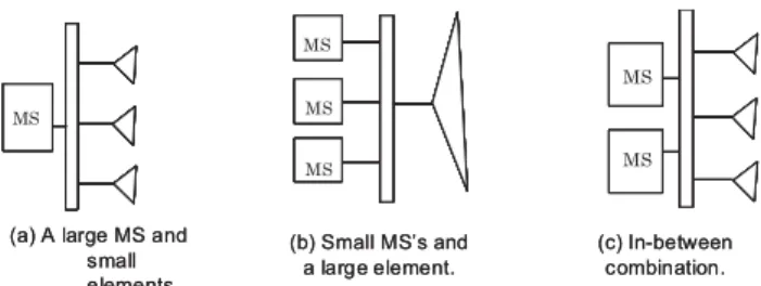
We can conceive three ways to manufacture such a large antenna, as shown in Fig. 6 [15]. The antenna with a single parabola in figure (c) is not practical but only refer- ential. The Reference System assumes a large array antenna with several hundred billion dipoles, as shown in figure (a).
In order to reduce the element number, we proposed an ar- ray of parabolas that fills the aperture area most densely, as shown in figure (b) [16]. In this case, the periphery of each parabola should be hexagonal, so that its primary radiator
Fig. 5 The requirement of the beam configuration [15].
Fig. 6 Three ways to manufacture an extremely large antenna [15].
should have a beam with a hexagonal cross-section [17].
At present, an array antenna with small elements of half-wavelength size as shown in figure (a) is considered most promising due to its beam steering capability. How- ever, the element number is tremendous so that mass- production is inevitable for the antenna elements as well as associated components. And the feed network must be sim- plified as much as possible.
A larger element in Fig. 6 must radiate a larger power.
Accordingly, the connection of an element and a microwave source has variations as shown in Fig. 7. A constituent unit of the Reference System corresponds to Fig. 7(a), though the SPS 2000 System to Fig. 7(c).
The actual way of installation and connection depends on the types of antennas and circuit components. A dipole, for example, is suitable for feeding by a balanced line so that
Fig. 7 Connection of microwave sources and radiating elements.
MS: microwave source.
a component with a balanced output can be placed on the substrate surface, and directly connected to the dipole. On the other hand, a patch is easily fed at one point by a probe.
Consequently, a component with an unbalanced output can be placed on the backside of the substrate, and one of the lines is connected to the patch through a hole.
The beam propagates along a path through the atmo- sphere with thermal coupling, or through the ionosphere with non-linear coupling [18]–[20]. The resultant irregular distribution of dielectric constant in space may cause the de- formation and migration of the beam profile, as is expected considering the propagation of a laser beam in the atmo- sphere. Therefore, the effects should be studied with much care.
(4) Rectification of microwave power and connection to a commercial power grid
The rectenna is 5 km in diameter in the Reference Sys- tem. This size exceeds the “common sense” of current an- tenna technology. The largest antenna on the ground is the fixed parabola with 300 m diameter at Arecibo in Puerto Rico, or the fully steerable parabola with 100 m diameter at Effelsberg in Germany [14].
On the other hand, the rectenna may be constructed as an assembly of smaller elements such as apertures or half- wavelength elements. In this configuration, each element or several elements are followed by a rectifying circuit, and the DC output is combined with the others. The fact that each power component loses the phase information may be beneficial for manufacturing the antenna with less accuracy.
The diode number in a rectenna is given by the to- tal RF input divided by the power handling level of each diode. Therefore, a diode should handle a large power at mi- crowave frequency in order to reduce the diode number and eventually to lower the output impedance of the rectenna.
Moreover, the energy conversion efficiency should be high.
On the other hand, there are already two related devices:
a high power rectifying diode of several kW at 50 or 60 Hz, and a microwave detector with a power of several mW. Com- paring the characteristics of these diodes, the requirements of SPSS diodes are not easy to fulfill.
An SPSS satellite in GEO does not suffer from power interruption due to solar eclipse or thick clouds. A satellite in LEO appears above a rectenna only intermittently, but the time is predetermined. Accordingly, the connection of SPSS to the power grid is much easier than terrestrial solar power
generation systems with strong weather dependence [4].
(5) Control of microwave beam
The radiated beam from a spacetenna should be kept within the aperture of a rectenna. However, the beam may migrate due to many disturbances: mechanical fluctuation of the satellite, thermal deformation of the spacetenna, and tur- bulence of the propagation media. Therefore, precise beam control is inevitably required in SPSS.
One method is so-called retro-directive control where the spacetenna automatically adjusts the beam direction ac- cording to the uplink signal [21]. Quick response is an ad- vantage of this scheme. However, the frequency relation to the high power downlink, and the constitution of the receiv- ing antenna onboard are issues in consideration of the ob- tainable S/N ratio and the pattern degradation of the down- link beam.
The other method is a conventional feedback loop sys- tem. Sensors on the ground sense the downlink footprint and eventually the deviation of the beam. The deviation in- formation and control signal are transmitted to the satellite via the up-link. Then, the downlink beam is adjusted accord- ing to the control signal. This scheme has much flexibility for the system design, and secure operation. However, the response may be slower than the retro-directive control.
In case of emergency, the beam should be controlled to avoid hazard extension. The response should be quick, and the associated change of system architecture should as small as possible.
(6) Thermal control
In the case of the Reference System, DC power of 8 GW is generated, and RF power of 5 GW is output to space. As a result, the difference of 3 GW has to be dis- sipated as heat, which should be well disposed of without damaging the internal components.
In space, heat is transferred between a satellite and the surrounding space only by radiation. Convection makes no contribution. Accordingly, devices with high efficiency are important, as well as excellent thermal control design.
(7) Interference with conventional radio wave systems Though an SPSS will probably use an ISM frequency, other systems operate in the same frequency band: Blue- tooth and wireless LANs in 2 GHz-band, and ETC (Elec- tronic Toll Collection) systems in 5 GHz-band. Moreover, an SPSS may generate harmonics due to the non-linearity of internal devices. It is necessary to study the interference and to reduce its effect as much as possible, before we pro- ceed to the development stage of an actual SPSS [3].
(8) Effects on living things
Microwave systems are criticized for having ill-effects on living things through heating and non-heating effects [22]. The power limit is specified in the IEEE document to be less than 1.0 mW/cm2for non-professional person [23].
We have to at least keep within the power density regulation.
(9) Space structure
An SPSS is a huge system, as described above. The weight of the Reference System is twenty kilo-tons that is 50 times heavier than the International Space Station (ISS). Therefore, the architecture and the way of construc- tion should be studied.
People cannot stay in space for the total construction period. Consequently, automatic assembly is inevitable. For example, a spacetenna could be carried to orbit as modules.
Each module is fixed in the target position and deployed au- tomatically.
(10) Transportation to orbits
The Reference System is to be located in GEO so that each module should be launched first to LEO using a chem- ical fuel launcher, then to GEO using slow but efficient propulsion such as electrical propulsion. On the other hand, in an SPSS in LEO, a module can be transported to orbit by one flight.
In either system, each module is so large that launch- ing to orbit is critical. If we use H-IIB rocket of Japan for the transportation of the Reference System only to LEO, the flight should be more than 1105 times so that the launch cost is a key to commercialize SPS. In the USA, companies are developing new types of launcher to drastically reduce the launch cost. Falcon 9 is for logistics to ISS, and Space Ship 2 for space tourism [24]. If the launch cost is reduced to 1/40 from the current value, the study result showed that SPSS could be competitive with conventional power gener- ation, such as thermal or atomic power generation.
In concluding this section, we have seen that the ampli- fiers, rectifiers and passive components in SPSS must han- dle large power levels at several GHz, which is comparable with a conventional power system at AC frequency. More- over, the number of elements is beyond current experience.
For example, the antenna elements in the Reference System exceed 2×10⁸in number. Accordingly, our old paradigm of microwave and antenna engineering should be shifted: (i) from low power to high power, and (ii) from a-la-carte pro- duction to mass-production.
4. Current Research Results in the Relevant Mi- crowave and Antenna Engineering
4.1 Microwave Amplifier and Phase Shifter
The most efficient HPA at present was developed at 5.65 GHz using GaN HEMT technology in Japan [25]. The cut-off frequency is approximately 29 GHz, which covers the fourth harmonics of 5.65 GHz. Therefore, class F op- eration is possible. The response of the HPA is shown in Fig. 8. The power added efficiency (PAE) was as good as 79%, and the drain efficiency reached 90%. The output level was 2.2 W.
The phase shifter should have sufficient accuracy and precision in addition to large power handling capability to
Fig. 8 The measured response of a class-F amplifier at 5.8 GHz [25].
Fig. 9 Configuration of an Ultra-Low Profile Dipole (ULPD) [27].
realize precise beam control. A phase shifter of MEMS technology is being developed in Japan. The MEMS switch is not of a conventional torsion-bar type, but of a cantilever type that is suitable for dual-pole operation and ohmic loss reduction [26].
4.2 Constitution of a Transmitting Antenna (Spacetenna) For the mass-production of antennas, the followings are im- portant.
(1) Simple radiating element
In the Reference System, a half-wavelength dipole that is located a quarter wavelengths above a reflector is adopted as a radiating element. Such a high profile radiator is not convenient to fold the antenna panels in the launch phase.
An Ultra-Low Profile Dipole was proposed to realize the antenna by laying a coaxial cable on the reflector, as shown in Fig. 9 [27]. ULPD has a simple structure and wide fre- quency characteristics in virtue of a built–in balun.
However, in order to mass-produce radiators, a printed antenna on a substrate is most suitable. A patch antenna and a printed dipole with a built-in balun are those candidates [28].
Fig. 10 Effectiveness of partial drive technique in a four-element array [29].
Fig. 11 Two types of partial drive technique.
(2) Reduction of driven elements and feed network
The complexity of a feed network can be relaxed to less than half by a novel technique of partial drive, which is shown in Fig. 10. Four radiating elements in free space are drawn in figure (a), and only two of them are really driven through transmission lines. The remaining two are parasitic, and are just metallic rods. The parasitic elements are excited by the radiated wave from the driven elements, as shown in Fig. 11(a). By optimizing the arrangement, the gain of the partially driven array is almost the same as that of the equivalent array whose elements are all driven, as shown in figure (b) [29].
An actual antenna for practical application is often backed with a reflector. In this case, the reflected wave must be taken account in addition to the direct wave for coupling estimation, as shown in Fig. 11(b). An array antenna with four driven and six parasitic elements were optimized in the arrangement to show the validity of partial drive technique [30].
In a partially driven array antenna, grating lobes tend to appear due to a slight difference of amplitude between adjacent driven and parasitic elements. A novel algorithm to arrange two kinds of elements was proposed to suppress the grating lobes, as shown in Fig. 12 [31].
In order to reduce the number of phase shifters and HPAs, a large array antenna is divided into sub-arrays, each of which is attached with a phase shifter. In this scheme, the elements in each sub-array are in phase, and the beam is steered according to the phase difference between the sub- arrays. As the antenna characteristics tend to be degraded, the radiation patterns were analyzed and formulated. The result is shown in Fig. 13 in the case of a one-dimensional array with 2 sub-arrays and 3 elements in each sub-array
Fig. 12 Grating lobe suppression in a partially driven array [31].
driven element,parasitic element.
Fig. 13 Radiation pattern of an array antenna as an assembly of sub-arrays. The phase difference between the sub arrays is3Δ[32].
Fig. 14 Array antenna with multiple-folding structure [33].
[32]. Consequently, the size of a sub-array can be compro- mised to reduce the gain decrease, grating-lobe appearance, and the deviation of the beam direction.
(3) Deployable Antenna Structure
Radiating elements are installed on a substrate panel, and many panels are folded for launch on a rocket. Con- sequently, the division of the total antenna and the fold- ing structure affect the folding efficiency. Multiple-folding structure of antenna panels is proposed as a basic structure of an antenna, as shown in Fig. 14 [33]. In this case, the el- ements on adjacent panels have a phase bias due to a panel step so that the phase of each element should be adjusted according to the desired direction.
Fig. 15 Beam diffusion in the case of emergency [35].
4.3 Beam Control
A retro-directive system using spread-spectrum signals on the uplink has been proposed. The direction of wave arrival is computed onboard, and the control signal is generated by software [34]. The advantages are: (i) The uplink frequency can be independent from the downlink frequency, in con- trast to a hardware retro-directive system. (ii) The system is robust against interference. (iii) Multiple rectennas can be managed due to the discrimination capability of the signal.
As a countermeasure against an emergency, the system shown in Fig. 15 was proposed [35]. The transmitted beam is expanded instantaneously by rearranging the phases of all radiating elements following a proposed algorithm. As a result, the radiated fields are not summed to cause sponta- neous side lobes probabilistically, and the radiated power is not concentrated on a small number of components.
4.4 Constitution of Receiving Antenna (Rectenna) In 1977, a large GaAs power diode was developed at 2.4 GHz. The conversion efficiency from RF to DC power came up to 91.4% at 7 W input, though the details of the ex- periment are not clear [36]. In Japan, efficiency of 76% at 5.8 GHz, without reflection loss, was obtained using a GaAs diode [37]. The power level was 3 W.
As stated before, GaN has many attractive features for a high-power diode. A novel diode with a ten finger elec- trode and its relevant rectifier were developed at 2.45 GHz [38]. The main parameters are as follows:
On-resistance 2.0Ω, Zero V-capacitance 0.36 pF, Break- down voltage 90 V, Size 890µm×1900µm for a chip. A rectifying circuit using the above-mentioned diode was de- veloped. The characteristics of conversion efficiency and re- flection ratio are shown in Fig. 16. The maximum efficiency is 75% at the optimum power level of 5 W.
In a practical application in a large power system, the diodes should be connected in serial and/or parallel. An ex- periment to generate 29 W was performed using 97 diodes [39]. The diodes were classified in three serial blocks, each
Fig. 16 The conversion efficiency and reflection ratio of a GaN diode at 2.45 GHz [38].
of which was composed of diodes in parallel. Before the system experiment, they tested each rectifier to show no breakdown at the specified power level of 300 mW per rec- tifier. However, in actual operation, seven diodes in the central region of the array were broken through insulation breakdown. The cause of the failure is now under study.
5. Strategy for the Realization of a System
There have already been several R&D study groups on SPSS, even only in Japan. This situation is understandable, as SPSS is a novel and unprecedented system. We have to discuss the most appropriate scheme before starting the de- velopment phase that will need much money.
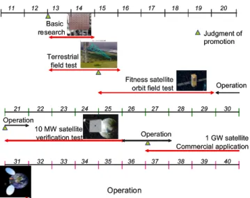
An R&D schedule following the author’s personal idea is shown in Fig. 17, based on the author’s experience in a research and development division [40]. This schedule in- cludes some basic principles that may be applicable to large- scale R&D planning in general.
As a first step, we have to focus on solving critical problems using a limited amount of money. In order to ac- complish this, most appropriate research themes should be selected.
As the second step, we have to demonstrate the fea- sibility of the system on the smallest scale, including the launch of a satellite to orbit. The scale of the satellite is an important issue to be discussed. If we want to show the power transferred from the satellite, the power level should be sufficient to satisfy people. Instead, if we confirm the most critical issue in orbit, which may be sending a beam to a rectenna aperture, the size of the spacetanna is a more important parameter than the power level.
Before starting the commercial phase, we have to demonstrate the system availability with sufficient power level to attract investors. The minimum power level depends on the group in question, and may be around 10 kW with sufficient capability of the beam.
In the final stage of R&D, a commercial satellite will be realized with a sufficient amount of fund, which may be 2 trillion yen. The amount of generated power should result in superior cost competitiveness against conventional power
Fig. 17 An example of the R&D schedule of SPSS development. The year of xy represents 20xy.
generation. It can be considered advantageous that SPSS needs almost no operational cost for providing fuel, different from thermal or atomic power generation.
At the time of judgment in the figure, the results of the former step are evaluated objectively, and their adequacy for the next step should be approved. Through the whole R&D process, the schedule should be consulted or managed by commercial interests who are responsible for the final in- vestment. Otherwise, decisions in the process may be dis- torted by political considerations.
6. Conclusions
In this paper, the outline of SPSS was explained to show its novelty and unusualness. The technical details show the difficult target for each device, and encourage R&D activity with indications of achievement. There are many R&D top- ics including components, subsystems, and the total system that range from electrical engineering, mechanical engineer- ing, and architecture to materials.
In relation to microwave and antenna engineering, it was shown that components in SPSS must handle high power levels. Accordingly, microwave engineering should be innovated to become High Power Microwave Engineer- ing rather than conventional microwave engineering for communications and radar.
Moreover, special designs suitable for mass-production are needed for radiating elements, feed networks and the associated active and passive components. At this stage, an antenna and components should be combined and designed as a whole. Consequently, we have to exploit a new field of microwave and antenna engineering to be called Mass- production Microwave and Antenna Engineering.
Along these new paradigms, many contributions and proposals have been made in Japan, as introduced above.
Some of them are to enhance the component characteristics at high frequency and high power level, and the others are
to promote mass-production of devices.
The process to realize the final SPSS includes over- coming several difficulties. As shown in the author’s idea of the long R&D schedule, it is critically important to have close contact with final investors, and to show fundamental and timely demonstrations.
Note: ISM
This word stands for Industry, Science and Medical.
The ISM frequencies were used mostly as energy sources, but nowadays a part of the frequency band is co-used with communications. For example, 2.45 GHz-band is with Blue- tooth and wireless LAN, and 5.8 GHz-band is with ETC (Electronic Toll Collection) system.
Acknowledgments
I would like to thank relevant SPSS researchers for provid- ing me with data and opportunities for discussion for this paper.
References
[1] M.A. Strom ed., Societal Issues, Scientific Viewpoints, American Institute of Physics, 1987.
[2] H. Matsumoto, “Research on solar power station and microwave power transmission in Japan: Review and perspectives,” IEEE Mi- crow. Mag., pp.36–45, 2002.
[3] “URSI White Paper on Solar Power Satellite (SPS) Systems and Re- port of the URSI Inter-Commission Working Group on SPS,” URSI Inter-commission Working Group on SPS, June 2007.
[4] T. Takano, The Solar Power Satellite for a Future of Energy — Space Electricity to a Home (in Japanese), Ascii Media Works, Tokyo, 2012.
[5] N. Shinohara (supervise.), IEICE (ed.), Solar Power Satellite/Station (in Japanese), Ohmsha, Tokyo, 2012.
[6] J.M. McSpadden and J.C. Mankins, “Space solar power programs and microwave wireless power transmission technology,” IEEE Mi- crow. Mag., vol.3, pp.46–57, Dec. 2002.
[7] P.E. Glaser, “Power from the Sun: Its future,” Science, vol.162, pp.857–866, 1968.
[8] G.M. Hanley, “Satellite power systems (SPS) concept definition study I-executive summary,” NASA, CR-3317, 1980.
[9] U.S. Department of Energy, “The smart grid: An introduction,”
http://energy.gov/sites/prod/files/oeprod/DocumentsandMedia/ DOE SG Book Single Pages%281%29.pdf
[10] M. Nagatomo, S. Sasaki, and Y. Naruo, “Conceptual study of a so- lar power satellite SPS 2000,” 19th International Symp. on Space Technology and Science, ISTS-94-e-04, May 1994.
[11] New Energy and Industrial Technology Development Organization,
“NEDO renewable energy technology white paper,” (in Japanese), 2011.
[12] N. Shinohara, H. Matsumoto, and K. Hashimoto, “Solar power sta- tion/satellite (SPS) with phase controlled magnetrons,” IEICE Trans.
Electron., vol.E86-C, no.8, pp.1550–1555, Aug. 2003.
[13] F.H. Raab, “Class-E, class-C, and class-F power amplifiers based upon a finite number of harmonics,” IEEE Trans. Microw. Theory Tech., vol.49, no.8, pp.1462–1468, Aug. 2001.
[14] T. Takano, A. Ogawa, K. Sakaniwa, H. Kobayashi, N. Toyama, and Y. Arimoto, Space Communications and Satellite Broadcasting, (in Japanese), Space Engineering Series 4, Corona Publishing, 2001.
[15] T. Takano, A. Sugawara, and S. Sasaki, “System considerations of onboard antennas for SSPS,” The Radio Science Bulletin, no.311,
pp.16–20, Dec. 2004.
[16] Y. Murao and T. Takano, “An investigation on the design of a trans- mission antennas and a rectenna with arrayed apertures for mi- crowave power trasmission,” IEICE Trans. Commun. (Japanese Edi- tion), vol.J81-B-II, no.1, pp.46–53, 1998 (in Japanese). Electronics and Communications in Japan, vol.83, no.2, pp.1–9, 2000 (trans- lated to English).
[17] E. Hanayama, K. Asari, and T. Takano, “Investigation on the radi- ation characteristics of a horn antenna with hexagonal beam,” (in Japanese), IEICE Com. Soc. Convention, B-69, 1995.
[18] R. Furuhama and S. Ito, “Effects of high power microwave propa- gation to unionized armospere,” (in Japanese), Review of the Radio Research Laboratories, vol.28, no.148, pp.715–721, 1982.
[19] F.W. Perkins and R.G. Roble, “Ionospheric heating by radio waves:
Predictions for Arecibo and the satellite power station,” J. Geophys.
Res., vol.83, no.A4, pp.1611–1624, 1978.
[20] H. Matsumoto, “Microwave power transmission from space and related nonlinear plasma effects,” Radio Science Bulletin, no.273, pp.11–35, June 1995.
[21] L.C. Van Atta, “Electromagnetic reflector,” U.S. Patent 2908002, Oct. 1959.
[22] J. Lin, “Space solar-power stations, wireless power transmissions, and biological implications,” IEEE Microw. Mag., vol.3, pp.36–42, March 2002.
[23] IEEE Std C95.1, “IEEE standard for safety levels with respect to human exposure to radio frequency electromagnetic fields, 3 kHz to 300 GHz,” 2005.
[24] R.M. Dillon, “Virgin Galactic spaceship makes 1st powered flight,”
Yahoo News, May 1, 2013.
[25] M. Kamiyama, R. Ishikawa, and K. Honjo, “5.65-GHz high- efficiency GaN HEMT power amplifier with harmonics treatment up to fourth order,” IEEE Microw. Wireless Compon. Lett., vol.22, no.6, pp.315–317, June 2012.
[26] D. Yamane, W. Sun, H. Seita, S. Kawasaki, H. Fujita, and H.
Toshiyoshi, “A Ku-band dual-SPDT RF-MEMS switch by double- side SOI bulk-micromachining,” IEEE/ASME J. Microelectromech.
Syst., vol.20, no.5, pp.1211–1221, 2011.
[27] A. Thunvichit, T. Takano, and Y. Kamata, “Ultra low profile dipole antenna with a simplified feeding structure and a parasitic element,”
IEICE Trans. Commun., vol.E89-B, no.2, pp.576–580, Feb. 2006.
[28] T. Takano, K. Saegusa, Y. Tsunemitu, O. Sato, and T. Suda, “Pro- posal of the integrated installation of ULPD antennas in CPW type and feeding devices,” (in Japanese), Proc. 2010 IEICE Society Con- ference, B-1-187, 2010.
[29] M. Okumura, T. Imura, N. Kamo, A. Sugawara, and T. Takano,
“Theoretical and experimental study on a partially driven array an- tenna with simplified dipole elements,” IET Microwaves, Antennas
& Propagation, vol.2, no.7, pp.696–703, March 2008.
[30] T. Takano, T. Imura, M. Okumura, and Y. Kazama, “A partially driven array antenna with parasitic elements of 60% in number,”
Fr1.8.3, EUCAP07, Edinburgh, UK, Nov. 2007.
[31] T. Suda, T. Takano, and Y. Kazama, “Grating lobe suppression in an array antenna with element spacing greater than a half wavelength,”
IEEE AP-S & URSI 2010, Toronto, July 2010.
[32] T. Takano and K. Saegusa, “Analysis of a large phased array antenna in assembly of sub-arrays attached with phase shifters,” IEEE AP-S
& URSI 2013, 127.1, Orlando, USA, July 2013.
[33] T. Takano, H. Hosono, K. Saegusa, Y. Miyazaki, K. Uchiyama, and Y. Araki, “Novel phased array antenna in a multiple folding scheme and its application to a satellite,” ISAP2011, WeG3-1, Jeju, Korea, Oct. 2011.
[34] K. Hashimoto, K. Tsutsumi, H. Matsumoto, and N. Shinohara,
“Space solar power system beam control with spread-spectrum pilot signals,” The Radio Science Bulletin, no.311, pp.31–37, 2004.
[35] T. Takano and K. Saegusa, “Instantaneous expansion of a collimated beam to a wider pattern to cope with system energencies,” IEEE AP- S & URSI 2012, 559.5, Chicago, USA, July 2012.
[36] W.C. Brown, “Electronic and mechanical improvement of the re- ceiving terminal of a free-space microwave power transmission system,” Raytheon Company, Wayland, MA, Tech. Rep. PT-4964, NASA Rep. CR-135194, Aug. 1977.
[37] Y. Fujino, N. Kaya, and T. Saka, “Development of a C band rectenna for microwave power transmission toward a space robot,” Acta As- tronautica, vol.50, no.5, pp.295–300, March 2002.
[38] J. Ao, K. Takahashi, N. Shinohara, N. Niwa, T. Fujiwara, and Y.
Ohno, “S-parameter analysis of GaN Schottky diodes for microwave power rectification,” Compound Semiconductor Integrated Circuit Symposium (CSICS), pp.1–4, 2010.
[39] T. Fujiara, K. Nagano, K. Hasegawa, M. Furukawa, Y. Kobayashi, S.
Mihara, and T. Saito, “An experimental study on failure in 5.8 GHz rectenna-array,” (in Japanese), IEICE Technical Report, SPS 2008- 06, July 2008.
[40] M. Mohri, T. Takano, and M. Hiramatsu, “How are you interested in, and how much will you pay for the large-scale projects of space research,” (in Japanese), Science Coffee Panel, Tokyo, Jan. 25, 2013.
Tadashi Takano received B.S., M.S., and Ph.D. degrees in Electric and Electronic Engi- neering from the University of Tokyo, in 1967, 1969, and 1972, respectively. He joined the Electrical Communication Laboratories of Ni- ppon Telegraph and Telephone (NTT) Public Corporation in 1972. He moved to the Insti- tute of Space and Astronautical Science, Japan, in 1984. In 1991 he became Professor in Elec- tronic Engineering in the Graduate School of the University of Tokyo. From 2008, he works in Electronic Engineering of Nihon University. His current research inter- est includes antenna engineering, radio wave applications to a solar power satellite system and natural hazard detection, and space communications.
Dr. Takano is a member of IEEE (Fellow), Institute of Electrical Engi- neers of Japan, URSI, Seismology Society of Japan, American Geophys- ical Union, Japan Society for Aeronautical and Space Science, and Japan Rocket Society.

![Fig. 4 The system configuration of the SPS 2000 System [10].](https://thumb-ap.123doks.com/thumbv2/123deta/5626238.1500260/2.892.113.387.419.656/fig-configuration-sps.webp)
![Fig. 5 The requirement of the beam configuration [15].](https://thumb-ap.123doks.com/thumbv2/123deta/5626238.1500260/3.892.508.774.118.357/fig-requirement-beam-configuration.webp)
![Fig. 8 The measured response of a class-F amplifier at 5.8 GHz [25].](https://thumb-ap.123doks.com/thumbv2/123deta/5626238.1500260/5.892.478.806.115.371/fig-measured-response-class-f-amplifier-ghz.webp)
![Fig. 10 E ff ectiveness of partial drive technique in a four-element array [29].](https://thumb-ap.123doks.com/thumbv2/123deta/5626238.1500260/6.892.78.429.116.287/fig-ectiveness-partial-drive-technique-four-element-array.webp)
![Fig. 16 The conversion e ffi ciency and reflection ratio of a GaN diode at 2.45 GHz [38].](https://thumb-ap.123doks.com/thumbv2/123deta/5626238.1500260/7.892.97.409.119.347/fig-conversion-ciency-reflection-ratio-gan-diode-ghz.webp)