新世代インターネットと情報流通に関する研究
オスマン, エム, エム, オスマン
https://doi.org/10.15017/1441254
出版情報:Kyushu University, 2013, 博士(工学), 課程博士 バージョン:
権利関係:Fulltext available.
Research on Future Internet and Contents Delivery
Othman Othman M.M.
December 2013
I hereby declare that this thesis entitled "Research on Future Internet and Contents Delivery" is the result of my own research except as cited in the references. This dissertation has not been accepted for any degree and is not concurrently submitted in candidature of any other degree.
Signature :
Student : Othman Othman M.M.
Date : December 2013
Supervisor : Professor Koji OKAMURA
To my family; parents, wife, and children. I would not have done this without you.
Thank you for your endless love, encouragement, and support.
Abstract
Software Defined Networking (SDN) is an emerging topic that tracts attention due to its paradigm, that splits the control plane from data forwarding plane. According to which, the control plane is realized as the network operating system, which is responsible for controlling maintaining the state of the whole network. While the data plane is realized as the network equipment or devices that carry out instructions from the control plane and forwards the data packets. Where, SDN have defined OpenFlow as “key enabler for software-defined networks and currently is the only standardized SDN protocol that allows direct manipulation of the forwarding plane of network devices”.
OpenFlow was first introduced in 2008, as a part of Stanford University’s clean slate project. OpenFlow provides a specially designed way to control flows on the network equipment by the OpenFlow controller (control plane) through using the OpenFlow Protocol, and splits that from the data plane (network equipment). According to OpenFlow; decision making can be done and modified freely by the OpenFlow controller according to layer 2, 3, VLAN, and layer 4 headers while the forwarding is still done by routers or switches, in addition to, their original functionality. Moreover, OpenFlow defines actions to be performed on flows that can be either collection of statistics or usage data, forwarding packets, dropping packets, or manipulating packet’s headers.
Thanks to the flexibility provided by OpenFlow and SDN, many researchers embarked on providing new smart applications like; a virtualized network infrastructure, detection of DDoS attacks, measurement-aware routing, supporting QoS, run-time programming for network to support big data applications, and many others. It is believed that large number of new applications will be proposed to enhance the operation of current technologies and to provide even new applications.
At the beginning of the Internet, it served the role of delivering contents using the simple client server model. But as time passes number of users grew fast. As shown by studies in AKARI project [1]; that the traffic size increases by factor of 1.7 every year. Thus, causing the content serves to overload. Manny efforts were put to solve the server overloading problem; among them the concept of Content Delivery Network (CDN), which was introduced to provide high availability of the contents, and solve the previously mentioned problem by supporting multiple replica servers to serve the same contents. And to enable the CDN many technologies were introduced like, the concept of using DNS resolutions to point to different replica content servers, other way was to use routing based method as in the anycasting to deliver traffic to different replica servers, other way was to construct an overlay delivery network as in the P2P networks to help the server in providing service. However, each of those technologies had some advantages and disadvantages, for example; overlay solutions induced an increase in inter-network connections, because it lacked knowledge of the undelaying network. While, the DNS and routing based solutions lacked the ability to rapidly change the server information due to their stability constraints and delays.
And thus, this study approaches the server overloading problem using SDN, since it provides more flexibility, and deeper ability to control and manipulate traffic. In this study, Content Anycasting is proposed to be built on SDN, to achieve; traffic locality and thus reducing inter-network connections, fine granularity for more accurate redirection, rapid updating to cope demands of some applications, while protecting vital network topology information, and enable a server driven CDN for a more server friendly service.
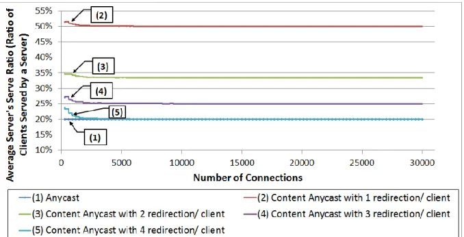
Simulation shows that using content anycasting with only a single content server; load can be reduced to 20% (in case that each client is capable of serving 4 other clients) which is the same load using 5 replica content servers in case of using the regular Anycast. Which means that according to the simulation content anycasting is capable of achieving the same load on content server as the regular anycasting while reducing the number of servers by 80%.
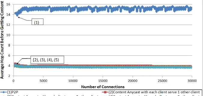
More over content anycasting showed that it is capable of reducing the average hop count
needed prior getting the content by 74%(in the case studied in this simulation), because it makes use of the network to redirect packets and so helps to redirect requests to a peer/server within the same network rather than randomly choosing peers regardless of their location.
Also, content anycasting showed it can be used to take the process of querying about peers/servers one step ahead by pre installing redirections on the network rather than having the server to reply to all of the queries. And thus it improves the availability of the server in many cases and especially in case of flash crowds.
However, the split of control and data planes comes with some cost. For example, there is a probability that the controller would be a source of bottleneck in the whole system.
This can be confirmed by, Michael Jarschel et al. who concluded in his study titled
“Modelling and performance evaluation of an OpenFlow architecture” that “When using OpenFlow in high speed networks with 10 Gbps links, today’s controller implementations are not able to handle the huge number of new flows.”. Moreover, the controller might be assigned more tasks if it has to debug or check to protect the network against malicious flow installations. Also, the controller can be under more burdens if the network has to support some service that produces a huge number of flows like P2PTV or content anycasting. For example, some statistics showed that PPTV – a popular P2PTV application – have 34 million unique daily visitors. Knowing the flow table size on the network equipment (router/switch) is also a limited resource.
Considering the case that the controller is under load to install and maintain huge number of flows; moreover, some of the network equipment are also overloaded (having low space in their flow table). To tackle the problem mentioned previously, this study proposed a hybrid control model that incorporates both centralized and distributed control plane. Where it is intend to keep the main control role to be played by the centralized controller, and provide some distributed control as an aid for the centralized one. This is done by proposing two features of SDN; aiming tackle problem in a different manner by enhancing the behaviour of some flows and by providing an enhanced control model for SDN. This results in giving SDN
more flexibility and more diverse control methods. Those features will help to relieve some load off the controller; also will help to make SDN self-aware and able to react when under heavy loads. Those two features are: Network equipment-to-equipment flow installation, and a new type of flows that are the proactive flows. Also, this study shows the proposed design of the required methods to secure the proposed distributed behaviour of the hybrid control plane.
In order to assess the efficiency of the proposed control model, simulation of a network with some overloaded equipment is implemented, under the assumption that the controller is also overloaded and cannot do any further processing or relocation of the flows to be installed, and thus continuously sends new flows to be installed into network equipment. According to the simulation the proposed hybrid control model was able to limit the growth of the flow table size of the overloaded equipment to, while in case of the original design, the table size of the network equipment kept on growing.
Acknowledgements
All praise is due to Allah almighty God for all the graces, and blessings bestowed upon my family and me during my study in Kyushu University and living at Fukuoka, Japan.
“Those who do not thank people, they do not thank God”. Words may not convey the true feelings of gratitude, and appreciation towards those who stood by my side, and supported me during my study.
First of all, I would like to express my gratitude towards my supervisor Professor Koji OKAMURA, whom without his wisdom and guidance; this work would not be possible. He was always there to show me the path and guide me through the difficulties of my study and research by his wise advice, discussions, and encouragement.
I would like to show my gratitude towards my loving wife, who has always stood by my side, took my hand and encouraged me to do my best. Also not to forget my lovely daughter and son, whose laughs are the joy of my life and have always been giving me strength to go on.
I also would like to show my deep gratitude to my loving parents, who have been my first teachers as they taught me about life, and have always been encouraging me to achieve more and do my best. And also I’m very grateful to my work to my father and mother in law, whose motivation and support has been always helping me.
In addition, I would like to express my gratitude to Professor Akihiro NAKAO, Professor Mutsumi AOYAGI, Professor Hirofumi AMANO, Professor Yasuo OKABE, for their kind support, guidance, and enlightening discussions throughout the meetings along my PhD study. Meetings they attended were really pleasant and fruitful, thanks to their kind comments, and advice that helped a lot to shape my work.
I would like to express my gratitude towards all members of Professor Okamura’s laboratory; Mr Kang Joon Suk, Mr Hiroki Sato, Mr Nakamura Ryo, Mr Keisuke Ookura, Mr Heru Sukoco, Mr Chengming Li, Ms Nan Li, Mr Kentaro Hayashi, Mr Cho, Mr Fuji, Mr Yamato, Mr Ramadhan Praditya Putra, Mr Prasetyan Firdaus, Mr Alaa Allakany, Mr Nor Masri Sahri, Mr Yowaraj Chhetri, Mr Zhaolong Ning, and all others that have their place in memory. Thanks a lot for your kind accompany, comments, encouragement, and support.
Last but not least, I would like to thank the Japanese Ministry of Education, Culture, Sports, Science, and Technology for supporting my study in Japan, through the MEXT scholarship. Also, I would like to thank Kyushu University, and the Graduate School of Information Science and Electrical Engineering, and all their Professors and Officials for their kind support.
Table of Contents
Abstract ... i
Acknowledgements ... v
List of Figures ... x
List of Tables ... xiii
1. Introduction ... 1
1.1. Motivation and Goals ... 4
1.2. Composition of the Thesis ... 6
2. Literature Review ... 7
2.1. Software Defined Network (SDN) ... 7
2.1.1. Evolution of SDNs ... 9
2.1.2. Architecture of SDN ... 10
2.1.3. Brief Introduction to OpenFlow ... 11
2.2. Content Delivery ... 12
2.2.1. Methods for Delivering Contents ... 12
3. Problem Statement ... 24
3.1. Problem Overview ... 24
3.2. Related Works ... 26
3.2.1. SDN Related Works ... 26
3.2.2. CDN Related Works ... 27
3.3. Problem Statement ... 28
4. Content Anycasting ... 31
4.1. Motivation ... 31
4.2. Content Anycasting Design ... 32
4.2.1. Content Anycasting System overview... 32
4.2.2. Requesting Content ... 38
4.3. Steps for Using Content Anycasting ... 43
4.4. Evaluation of Content Anycasting ... 46
4.4.1. Assessment of Reduction in Server Load and Number of Content Servers 46 4.4.2. Assessment of Reduction in Hop Overhead Pre-getting the Content... 48
4.4.3. Assessment of Ability to Serve Flash Crowds ... 49
5. Hybrid Control Model of SDN ... 52
5.1. Motivation ... 52
5.2. Flow Aggregation Algorithm ... 53
5.3. Distributed Behaviour of the Hybrid Control Model ... 55
5.3.1. Protocol of the Distributed Behaviour ... 56
5.3.2. Usage Scenario of the Distributed Behaviour of the Hybrid Control Model 57 5.4. New Type of Flows: Proactive Flows ... 59
5.4.1. Proactive Flows Protocol ... 60
5.4.2. Usage Scenario of the Proactive Flows ... 61
5.5. Evaluation of the Distributed Behaviour of the Hybrid Control Model ... 63
6. Securing Distributed Behaviour in the Hybrid Control Model ... 68
6.1. Threat Model ... 68
6.2. Security Requirements/Goals ... 69
6.3. Building Blocks for the Security Methods ... 69
6.4. Proposed Security Mechanism ... 71
6.5. Proposed Security Algorithms ... 71
6.6. Usage Scenario ... 77
6.7. Attack Resistance ... 79
6.8. Discussion and Evaluation ... 81
7. Conclusion ... 83
References ... 88
Published Papers ... 97
Appendix ... 99
List of Figures
Figure 1: Software-Defined Network Architecture, as appeared in figure 1 of [21]. ... 10
Figure 2: Idealized OpenFlow Switch. The flow table is controlled by a remote controller via the secure channel. As shown in [7]. ... 11
Figure 3: Flow table entry. ... 12
Figure 4: Header fields. ... 12
Figure 5: DNS-based CDN, step 1. ... 14
Figure 6: DNS-based CDN, step 2. ... 14
Figure 7: Example of Anycast Implementation, a Routing-based solution. ... 16
Figure 8: Content Anycasting System overview. ... 32
Figure 9: Content Anycasting redirection request example. ... 33
Figure 10: An example of a redirection system with two autonomous systems and two anycast managers. ... 35
Figure 11: An example of the flow table entry generated by the redirection controller. ... 36
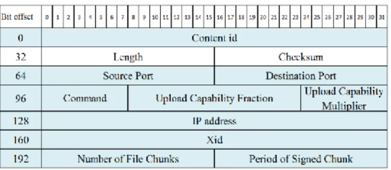
Figure 12: The Probe header (modified UDP), where the highlighting shows the modified fields. ... 39
Figure 13: Content request handshake, in case of redirection. ... 41
Figure 14: Content request handshake, in case of no redirection. ... 42
Figure 15: Steps for Using Content Anycasting: System initiation. ... 43
Figure 16: Steps for Using Content Anycasting: Content requesting. ... 44
Figure 17: Steps for Using Content Anycasting: Getting the content. ... 45
Figure 18: Steps for Using Content Anycasting: Reporting to server about getting content from another client. ... 45
Figure 19: The content server load in case of using current anycast, and content any casting with 4 cases; where each client is capable of serving 1,2,3,4 other clients. ... 47
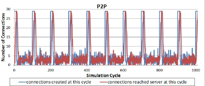
Figure 20: The average distance in hops that the client request have to travel prior to get the content in case of using central management P2P, and content any casting with 4 cases; where each client is capable of serving 1,2,3,4 other clients. ... 49 Figure 21: Connections created by clients and connections served by the server in each cycle
of the simulation in case of regular P2P with central management. ... 50 Figure 22: Connections created by clients and connections served by the server in each cycle
of the simulation in case of content anycasting. ... 50 Figure 23: Main Skeleton of the Flow Aggregation Algorithm (finding flows to be aggregated
and aggregate them). ... 53 Figure 24: Step 2 in Figure 23: aggregating IP src or DST. ... 54 Figure 25: Main skeleton for the network equipment-to-equipment flow installation method.
... 55 Figure 26: Distributed SDN control protocol packets. ... 56 Figure 27: The case of flow installation: Regular flow installation: from controller to each
network equipment. ... 58 Figure 28: The case of flow installation: The flow installation using the proposed network
equipment-to-equipment flow installation. ... 58 Figure 29: The case of flow installation: Provider Edge (PE) router carries out flows that
manipulate headers. ... 58 Figure 30: The case of flow installation: PE router gets overloaded and delegates some flows
to the two adjacent P routers. ... 59 Figure 31: The case of flow installation: PE forwards packets and the two P routers
manipulate the headers. ... 59 Figure 32: Fields added to the flow installation packet in order to support proactive flows. .. 61 Figure 33: Server migration while maintaining IP: a usage scenario of the proactive flows:
Migration and Redirection using regular OpenFlow. ... 61 Figure 34: Server migration while maintaining IP: a usage scenario of the proactive flows:
Figure 35: Server migration while maintaining IP: a usage scenario of the proactive flows:
Migration and Redirection using OpenFlow and Proactive Flows. ... 62
Figure 36: Success Rate of the Flow Aggregation Rate ... 64
Figure 37: Network Used as a case assessment of the simulation. ... 65
Figure 38: Flow table size (y-axis) vs. time (x-axis), for the case of regular SDN control. .... 65
Figure 39: Flow table size (y-axis) vs. time (x-axis), for the case of the hybrid SDN control. 66 Figure 40: Ratio of flow table size on equipment under focus to the reset of network equipment, in both cases of regular SDN control and hybrid SDN control. ... 67
Figure 41: SEND_REQUEST Algorithm. ... 73
Figure 42: RECEIVE_BROADCAST Algorithm... 73
Figure 43: CHECK_INCOMING_REQUEST Algorithm. ... 74
Figure 44: RELAY_BROADCAST Algorithm. ... 75
Figure 45: RECEIVE_REPLY Algorithm. ... 76
Figure 46: Request sending. ... 77
Figure 47: Relaying Request. ... 78
Figure 48: Replying to request. ... 78
Figure 49: Accepting reply. ... 78
List of Tables
Table 1: Comparison of different CDN technologies and the goals they achieve. ... 25 Table 2: Table 1. List of Notations used in the algorithms following in this Section (variables,
and operations). ... 72
1. Introduction
Routing Protocols have played essential role in the operation of the Internet. Since the early beginnings of the Internet and until the time being; finding the best way for a packet to be delivered to its destination, has been one of the most pressing questions to be sought.
Beyond the simple static configuration of routes, many more routing protocols were proposed and deployed on routers to perform automatic configuration of routes. Many examples of routing protocols does exist, among the well-known are the Routing Information Protocol (RIP) [2] [3], Open Shortest Path First (OSPF) [4], Intermediate System to Intermediate System (IS-IS) [5], Border Gateway Protocol (BGP) [6], and many others.
In order to achieve the main target of the routing protocols, that is to find the best way for a packet to be delivered to its destination. Routing protocols tend to exchange route information between different routers, and then calculate within each router the best route for different destinations. This can be viewed from two points of view. First, from a whole network point of view the decision-making is done locally within each router. And in that essence, the decision making for the routing process can be classified under the distributed control model. Second, from the point of view of the place where decision-making is done, that is from the point of view of the control plane (decision-making) and data plane (packet forwarding). According to this point of view routing processed can be classified under a coupled control and data planes model; since the router is one who decides how the packets gets forwarded and does forward it according to that decision.
As explained in the previous paragraph that the current control of networks via routing protocols imposes a tight coupling between control plane and data plane. That is; the decision-making is done on the same device that does the data forwarding. However, it is believed that this tight coupling has led to the so-called “the Internet ossification” [7]. Due to the Internet ossification, it has become extremely difficult to deploy any new functionalities, applications, and protocols. Since, they will need to be implemented directly into the network
equipment (routers or switches). And this would be a very complex task, especially that all of the network equipment vendors does not allow to have direct access to the hardware of their equipment. Not to mention that vendors also tend to close the functionalities of their implementations, making their equipment more like back boxes with limited commands for configuring features of their implementations.
To overcome those difficulties of deploying new functionalities, applications and protocols; many workarounds has been invented. This is done mainly through middle-boxes as in case of firewalls, load balancers, network address translators (NAT), and many others.
Or through the use of overlay networks. This is evident in the workarounds done in case of the Content Delivery Networks (CDNs) [8].
Other ways to overcome those difficulties lies in changing the control model. One of the current research trends in this direction proposes to split the control plane (decision- making) from the data plane (packet forwarding). Where, the control plane is carried out in a separate machine than the data forwarding one. This split in control and data planes is one of the essential ideas that distinguish the Software Defined Networks (SDN). However, both the split of control and data planes, as well as the naming of SDN are not new, one of the earliest descriptions of both the naming and the split control concept was done in 1985 in [9] for voice and circuit-switched data services on the switched network.
Software Defined Networking (SDN) is an emerging topic that tracts attention due to its paradigm, that splits the control plane from data forwarding plane. According to which, the control plane is realized as the network operating system, which is responsible for controlling maintaining the state of the whole network. And the data plane is realized as the network equipment or devices that carry out instructions from the control plane and forwards the data packets. Where, SDN have defined OpenFlow as “key enabler for software-defined networks and currently is the only standardized SDN protocol that allows direct manipulation of the forwarding plane of network devices”.
OpenFlow was first introduced in 2008, as a part of Stanford University’s clean slate project. OpenFlow provides a specially designed way to control flows on the network equipment by the OpenFlow controller (control plane) through using the OpenFlow Protocol, and splits that from the data plane (network equipment). According to OpenFlow; decision making can be done and modified freely by the OpenFlow controller according to layer 2, 3, VLAN, and layer 4 headers while the forwarding is still done by routers or switches, in addition to, their original functionality. Moreover, OpenFlow defines actions to be performed on flows that can be either collection of statistics or usage data, forwarding packets, dropping packets, or manipulating packet’s headers.
Thanks to the flexibility provided by OpenFlow and SDN, many researchers embarked on providing new smart applications like; a virtualized network infrastructure in [10], detection of DDoS attacks [11], virtual network migration [12], for wireless mesh networks [13], measurement-aware routing [14], supporting QoS [15], multicasting in overlay networks [16], server load balancing [17], run-time programming for network to support big data applications [18], and many others. It is believed that large number of new applications will be proposed to enhance the operation of current technologies and to provide even new applications.
On another hand, since the beginning of the Internet, it served the role of delivering contents using the simple client server model. But as time passes number of users grew fast.
As shown by studies in AKARI project; that the traffic size increases by factor of 1.7 every year. Thus, causing the content serves to overload. Manny efforts were put to solve the server overloading problem; among them the concept of Content Delivery Network (CDN), which was introduced to provide high availability of the contents, and solve the previously mentioned problem by supporting multiple replica servers to serve the same contents. And to enable the CDN many technologies were introduced like, the concept of using DNS resolutions to point to different replica content servers, other way was to use routing based
construct an overlay delivery network as in the P2P networks to help the server in providing service. However, each of those technologies had some advantages and disadvantages, for example; overlay solutions induced an increase in inter-network connections, because it lacked knowledge of the undelaying network. While, the DNS and routing based solutions lacked the ability to rapidly change the server information due to their stability constraints and delays.
However, another issue rises with the architecture of SDNs; that is the split of control and data planes, which comes with some cost. For example, there is a probability that the controller would be a source of bottleneck in the whole system. This can be confirmed by, Michael Jarschel et al. who concluded in his study titled “Modelling and performance evaluation of an OpenFlow architecture” [19] that “When using OpenFlow in high speed networks with 10 Gbps links, today’s controller implementations are not able to handle the huge number of new flows.”. Moreover, the controller might be assigned more tasks if it has to debug or check to protect the network against malicious flow installations. Also, the controller can be under more burdens if the network has to support some service that produces a huge number of flows like P2PTV or content anycasting. For example, some statistics [20]
showed that PPTV – a popular P2PTV application – have 34 million unique daily visitors.
Knowing the flow table size on the network equipment (router/switch) is also a limited resource.
1.1. Motivation and Goals
Software Defined Networking (SDN) and its enabler technologies like OpenFlow provide unparalleled abilities for future applications to innovate and achieve smart functionalities that were not possible on the so-called “ossified Internet”; this can be done by enabling and simplifying network programmability for the future applications. The idea of enabling innovation of smarter future application, have been advocated by research and standardization bodies as in [21]; furthermore, SDN is often referred to as “A Radical New
One of the applications that can make a great advantage of the flexibility of SDN is the Content Delivery Networks (CDN), since the increase in the number of clients and contents sizes, as well as the increase in complexity of such solutions. And thus, this study aims to design a solution for CDN based on SDN, in a way that can achieve many advantages in the proposed solution, compared to achieving a sub-set of those advantages as done by other solutions.
Thus, this study tries to achieve a CDN with the following qualities. First, improving traffic locality and reducing inter-network traffic. Second, providing high level of granularity for the operation of the CDN and enabling it to work for a combination of specific contents and or server, rather than servers. Third, enabling rapid updates and changes to the structure of the CDN. Forth, protecting the underlying network’s vital information; like the topology of the network and its connections. Fifth, enabling the content servers to have a driving role in the CDN, this helps the CDN to coop with the needs of the servers as well as the other components of the CDN. Sixth, enabling the redirections’ (forwarding) decision-making to be done by the underlying network, along with enforcing the redirections to be carried out by the underlying network; this is helpful since, the underlying network knows its topology and is capable of making efficient decisions.
However, there are many debates related to the scalability of SDNs technologies. For example, some researchers concluded that the current OpenFlow’s controllers might not be able to handle a huge number of flows. Things can become more complicated if the controller is assigned more tasks like having to debug or check to protect the network against malicious flow installations. This would make it more difficult for SDN to support applications that can generate large number of flows, as in the case of some Content Delivery applications.
And thus, this study aims to give SDN more flexibility and more diverse control methods; which in turn, will help to make SDN self-aware and able to react when under heavy loads without incorporating the controller. It also, aims to keep the main control role to
be played by the centralized controller, and provide some distributed control as an aid for the centralized one. This can be helpful as an aid for the controller, or as a fail-safe mechanism that enables the controller and equipment to still handle huge number of flows while carrying other tasks without putting extra burden on the controller.
1.2. Composition of the Thesis
First, this study begins by providing explanation and background review of Software Defined Networks (SDNs), and methods of Content Delivery; in Chapter 2. Next, Chapter 3 explains about the problems under consideration in this work, and discusses related works.
Then, Chapter 4 explained the motivation, design, and evaluation of Content Anycasting.
After that, the motivation of the hybrid control model of SDNs, along with its design, usage scenario, and the design of proposed new type of flows (the proactive flows); are discussed in Chapter 5. Then, the proposed security methods for the SDN’s hybrid control model are discussed in Chapter 6. Finally, in Chapter 7 concludes this work.
2. Literature Review
This Chapter sheds more light on the major topics touched in this study that are; the Software Defined Networks and Content Delivery over networks. Through which, it intends to provide bases for better understanding for the later parts of this study.
2.1. Software Defined Network (SDN)
Routing Protocols have played essential role in the operation of the Internet. Since the early beginnings of the Internet and until the time being; finding the best way for a packet to be delivered to its destination, has been one of the most pressing questions to be sought.
Beyond the simple static configuration of routes, many more routing protocols were proposed and deployed on routers to perform automatic configuration of routes. Many examples of routing protocols does exist, among the well-known are the Routing Information Protocol (RIP) [2] [3], Open Shortest Path First (OSPF) [4], Intermediate System to Intermediate System (IS-IS) [5], Border Gateway Protocol (BGP) [6], and many others.
In order to achieve the main target of the routing protocols, that is to find the best way for a packet to be delivered to its destination. Routing protocols tend to exchange route information between different routers, and then calculate within each router the best route for different destinations. This can be viewed from two points of view. First, from a whole network point of view the decision-making is done locally within each router. And in that essence, the decision making for the routing process can be classified under the distributed control model. Second, from the point of view of the place where decision-making is done, that is from the point of view of the control plane (decision-making) and data plane (packet forwarding). According to this point of view routing processed can be classified under a coupled control and data planes model; since the router is one who decides how the packets gets forwarded and does forward it according to that decision.
As explained in the previous paragraph that the current control of networks via
decision-making is done on the same device that does the data forwarding. However, it is believed that this tight coupling has led to the so-called “the Internet ossification” [7]. Due to the Internet ossification, it has become extremely difficult to deploy any new functionalities, applications, and protocols. Since, they will need to be implemented directly into the network equipment (routers or switches). And this would be a very complex task, especially that all of the network equipment vendors does not allow to have direct access to the hardware of their equipment. Not to mention that vendors also tend to close the functionalities of their implementations, making their equipment more like back boxes with limited commands for configuring features of their implementations.
To overcome those difficulties of deploying new functionalities, applications and protocols; many workarounds has been invented. This is done mainly through middle-boxes as in case of firewalls, load balancers, network address translators (NAT), and many others.
Or through the use of overlay networks. This is evident in the workarounds done in case of the Content Delivery Networks (CDNs) [8].
Other ways to overcome those difficulties lies in changing the control model. One of the current research trends in this direction proposes to split the control plane (decision making) from the data plane (packet forwarding). Where, the control plane is carried out in a separate machine than the data forwarding one. This split in control and data planes is one of the essential ideas that distinguish the Software Defined Networks (SDN). However, both the split of control and data planes, as well as the naming of SDN are not new, one of the earliest descriptions of both the naming and the split control concept was done in 1985 in [9] for voice and circuit-switched data services on the switched network.
The next Subsection (2.1.1) discusses the evolution of the concepts of the SDNs in more recent studies. While, Subsection 2.1.2 discusses the architecture of SDNs, and elaborate its different parts.
2.1.1. Evolution of SDNs
In 1995 a series of workshops were held by the Open Signaling working group (OPENSIG), with the aim of “making ATM, Internet and mobile networks more open, extensible, and programmable” [23]. Their studies mainly focused on creating an open programmable interface in order to access the network equipment (hardware). Following those efforts, the General Switch Management Protocol (GSMP) working group was created under IETF. GSMP protocol [24] provides switch configuration control and reporting, port management, connection control, QoS and traffic engineering control and the reporting of statistics and asynchronous events for MPLS label switch devices, all either from or to a third party controller.
Another trend started in middle 1990s that is the Active Networking [25] [26].
According to Active networking two ways have been proposed to achieve their goals that are;
first, user-programmable switches, with in- band data transfer and out-of-band management channels. Second, capsules, which were program fragments that could be carried in user messages; program fragments would then be interpreted and executed by routers.
Since 2003, IETF’s Forwarding and Control Element Separation Working Group (ForCES) [27], has been working on defining an architectural framework and associated protocols to standardize information exchange between the control plane and the forwarding plane.
While on 2004 the 4D project [28], which is a clean slate project targeting the separation between the routing decision logic and the protocols governing the interaction between network elements. Moreover the 4D project, proposed giving the control plane a global view of the network, serviced by a dissemination and discovery plane. Some of those proposed principles later inspired the design on NOX [29]; which is an OpenFlow controller that is described as an “Operating System for networks”.
On 2006, Network Configuration Working Group of IETF proposed NETCONF [30].
NETCONF provides mechanisms to install, manipulate, and delete the configuration of network devices, in a manner that is identical to APIs. However, it does not state anything related to the separation of control and data planes.
In the same year 2006, Ethane [31], which is the immediate predecessor of OpenFlow, was proposed. Ethane represented new network architecture for enterprise networks. Ethane’s focus was on using a centralized controller to manage policy and security in a network.
2.1.2. Architecture of SDN
According to the Open Networking Foundation [21], SDN network consists of an Infrastructure Layer; that is formed by network devices (network equipment) interconnected to each other. This infrastructure layer communicates to the Control Layer through the use of the Control Data Plane Interface. One example of the Control Data Plane Interface is the OpenFlow protocol. And, the Control Layer consists of the controller that makes decisions for the network devices in the Infrastructure Layer. On top of the Control Layer, one or more applications operate in the Application Layer. Also, those applications of the Application Layer communicate with the Control Layer through a set of APIs.
Figure 1: Software-Defined Network Architecture, as appeared in figure 1 of [21].
2.1.3. Brief Introduction to OpenFlow
In order to elaborate the proposed contents anycasting design and the hybrid control model of SDN of this study, it is important to shed more light on OpenFlow which is part of Stanford University’s clean slate project originally aims to enable researchers to run their experiments on their actual production network giving them better chance of getting more realistic results than that of the simulation.
According to OpenFlow, modern switches or routers contains flow tables to implement firewalls, NAT, QoS and to collect statistics. While each vendor implements the flow table differently, OpenFlow identifies and exploits a common set of functions to enable its flow table and also provides the OpenFlow protocol to enable programming the flow table.
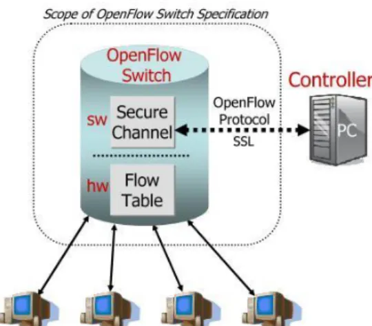
Any OpenFlow system as shown in [7] (see Figure 2) consists of the controller where the decision-making or routing takes place and the OpenFlow router or switch where the packet forwarding takes place.
Figure 2: Idealized OpenFlow Switch. The flow table is controlled by a remote controller via the secure channel. As shown in [7].
This provides more freedom and flexibility in the decision-making without overloading the routers or switches with this task. This freedom is gained by having a special controller that can be designed by developers or researchers according to their own needs and running their own code to implement or test new ideas without having to modify or change the existing networking infrastructure.
And in more details, any switch or router that supports OpenFlow must have all of the following OpenFlow components; a flow table, a secure channel to connect the switch or router to the OpenFlow controller and an OpenFlow protocol which is used as a protocol of communication between the switch or router and the controller over the secure channel. First of all, the flow table, which consists of flow entries (see Figure 3).
Figure 3: Flow table entry.
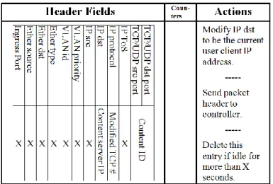
Where each flow entry consists of header fields to which the header of the incoming packet is matched against (see Figure 4), counters to provide statistics about the flow entry and actions to be performed to the matched incoming packet. The actions can be either forwarding the packet to physical port or ports, enqueue the packet in a queue attached to a physical port, dropping the packet or modifying incoming packet’s header fields, which include modifying fields shown in Figure 4.
Figure 4: Header fields.
2.2. Content Delivery
2.2.1. Methods for Delivering Contents
1) Client/Server
Client/Server model is the most basic model that was used to build the applications on the Internet like the web. According to [32] the client is the program that initiates communication to the other part, while the serve is the program that responds to the initiation.
Also the server is a program that provides a service while the client is a program that receives it.
If the pure client/server model was used as, the case of the usual content serves. This would mean that all of the client’s connections will be directed to the server. However, this would be the main weak point of the client/server model since the server will be the bottleneck and the single point of failure.
2) DNS-Based Solutions
As the Internet grew and the number of users increased, some issues relating to the operation of the servers on the Internet have raised to concern. One of them is server overloading, caused by the limited capabilities of the server and the increase of the clients in a way that exceeds the server’s capabilities. Therefore, one solution for the server-overloading problem is to increase the number of servers available to provide the same service by having multiple replica servers. However, in this solution a vital question had to be studied carefully which is; “how can a client determine to which replica server it should send its request?”.
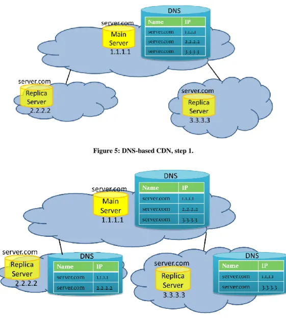
Many efforts have been done to answer this question, one the first was to use the DNS, as in [33], [34]. This is done by storing multiple entries to map the same server name to multiple IP addresses, as shown in Figure 5. A second DNS solution is to store different mappings in different DNS serves depending on their location for the same server name to the IP addresses of the servers that are located in the same autonomous system as the DNS server, as shown in Figure 6. The second DNS solution aims to direct clients to the server that is located within the same autonomous system, while the first DNS anycast solution aims to only to direct clients to more than one server. However all of the DNS based anycast solutions suffered from limitations that where inherited from the DNS system itself, like the slow of change and inaccurate resolutions of names because of DNS cashing.
Figure 5: DNS-based CDN, step 1.
Figure 6: DNS-based CDN, step 2.
3) Routing-Based Solutions
As a result, researchers sought alternative ways to implement anycasting rather than depending on DNS systems. This led them to implement anycasting system that depends on the network itself to divert the packets to the appropriate server, as in [35] and [36]. This means that the clients do not have to carry out any role in the process of finding out which replica server to send to, instead it sends packets to one IP address and the network itself (using the routers) will deliver those packets to the appropriate replica server.
This is done by assigning one IP address on all of the replica servers, so that all of the replica serves will have the same IP address. The next step will be to advertise this address to the routers in the network and those routers will propagate this advertisement through the network. As a result, each router will have multiple entries in its routing table for the same IP address (anycasting address) and will treat this as if it knows multiple paths to one node that has the anycasting address and will choose the path according to its routing decision measures like the choosing the path with the shortest path length or choosing the path with the least cost or other measures.
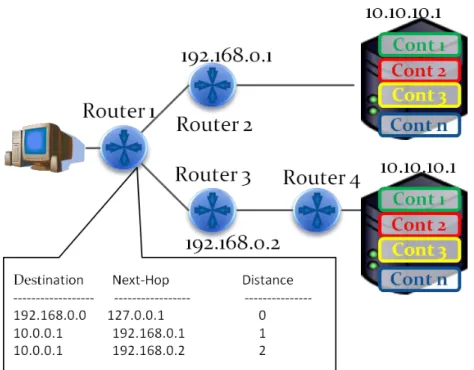
And to show that in a more detail, see Figure 7. In this figure there are two replica servers that have the same IP address (anycast address) that is “10.10.10.1”, both servers have advertised this address to the network and this advertisement have been propagated through the whole network. As a result, routers will have two entries in their routing table for the address “10.10.10.1” with different information like the next hop and distance, this means that each router will think that there is one node with the IP address “10.10.10.1” and it knows two routes to this node. This leads the router to choose the best rout depending on its routing protocol.
Figure 7: Example of Anycast Implementation, a Routing-based solution.
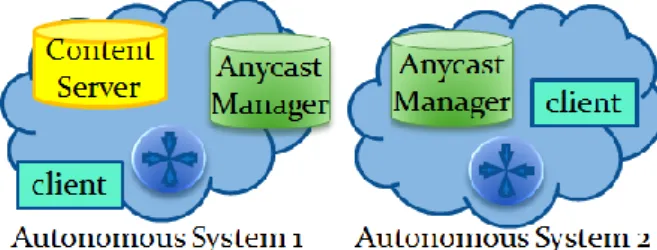
Network based anycast has many advantages, like having an accurate decision making (to choose to which replica server to deliver the packet to) this is due to depending on the routers to divert the packets since the routers have accurate knowledge about the topology of the network. This was explained in [35]; “When a service is anycast between two or more nodes, the routing system makes the node selection decision on behalf of a client.”. And that network-based anycast does not rely on the client in the process of finding the appropriate replica server; instead, it depends totally on the network the thing that makes it more effective and less prone to errors and attacks made by malicious clients. Another advantage is that anycast can be used achieve locality in service providing; that is to place a replica server within one network (e.g. in an autonomous system or a local network) and then advertise anycast redirections within this network which means that this server will be a local anycast server. The advantages of the locality achieved by anycast was described in [35] as; “to improve service response times by hosting a service close to other users of the network” , “to improve service reliability by providing automatic fail-over to backup nodes” and “to keep service traffic local in order to avoid congesting wide area links”.
While on the other hand, network based anycast have some limitations that are mostly inherited from the routing protocols. For example, network based anycasting have to comply to the rules of the routing protocol, like some safety hold backs done by the routers in order to avoid oscillation of modifying paths (as described in [35]), and the like the propagation delay that is the time needed for an advertisement (that has the redirection information) to propagate or reach all of the networks (this also was mentioned in [35]). The thing that limits the frequency in which anycasting can dynamically changes; “Rapid advertisement/withdrawal oscillations can cause operational problems, and nodes should be configured such that rapid oscillations are avoided (e.g., by implementing a minimum delay following a withdrawal before the service can be re-advertised)” as stated in [35] . Another limitation that the network based anycasting has is that it is stateless same as the routers that it depends on to provide the anycasting service, this is because routers do not care about the state of a state-full session like TCP, instead it deals with each packet individually rather than a part of a session.
And so network-based anycast is also stateless, which might cause it to deliver one packet in a state-full session to one replica server and then deliver the next packet in the same session to another replica server the thing that will cause the state-full session to fail. McPherson et al.
described this in [37] by “Stateful transport protocols (TCP, DCCP, SCTP), without modification, do not understand the properties of anycast and hence will fail probabilistically, but possibly catastrophically, when using anycast addresses in the presence of "normal"
routing dynamics”. This is the reason that also limits the use of anycast to some specific applications that does not depend on state-full protocols to provide service like DNS that depends on the UDP, which is a stateless protocol to resolve names. And the last limitation is that anycasting does not provide a method to have a selective redirection of packets, which means that packets can be forwarded to any replica server, and this forces all of the replica servers to have exactly all of the contents and prohibits using cases where the contents are distributed among many servers. Which was stated in [35]; “For a service distributed using anycast, that implies that different Anycast Nodes must operate in a consistent manner and,
where that consistent behaviour is based on a data set, the data concerned be synchronised between nodes”.
4) Overlay-Based Solutions
Another trend in solving the server-overloading problem is to use parts of the client’s resources (bandwidth, processing power, storage, etc.) in order to provide service to other clients. This is done by constructing an overlay network over the physical underlay network in order to have a new virtual network that is independent of the physical network. P2P delivery model have been used widely for delivering contents like in case of file sharing P2P networks, where many types of P2P file sharing applications have been produced each has its own protocols, applications, overlay network structure, and many other design specific characters. Examples for P2P file sharing networks include Gnutella, Kontiki, BitTorrent [38], Kazaa, and many others.
P2P networks can be classified into many different categories depending one of many characterising aspects. For example if P2P applications are classified based on their overlay network topology then they can be either structured (peers in the overlay network are structured to form a specific topology) or unstructured (peers are randomly scattered with no special topology), also P2P applications can be classified based on the way that they organize themselves so they can be either centralized (having a central entity like a special server or peer to organise and manage the overlay network) or decentralized (does not have a centralized entity to organize or manage the overlay network, it is fully distributed function).
Moreover, P2P applications can have many classifications based on many different characteristics they have. But this study will be focusing on the centralized and decentralized classifications because they are concerning about the management and maintenance of the P2P network, which is also the main focus in this study and so using this classification makes it easier to compare the proposed content anycasting against P2P applications.
To shed more light about P2P networks and to provide a better understanding of them it is important to show how P2P networks works. In order for a P2P network to be constructed, it must deal with two essential points:
Management of Peers: This means that a P2P system must be able to manage a list of peers that are currently using the system, inform new users that want to join the P2P system about other peers, and to be able to command the peers to form a specific desired topology.
Management of Contents: This means that a P2P system must know about the data or content that is exchanged within its network (for Content Delivery or File sharing), and must be able to provide information about the contents to any requesting peer.
Due to the nature of the proposed content anycasting, more focus will be given to the management of peers along the classification of the P2P networks according to the organising method (centralised management and decentralized management); where the details of each will be show as follows.
1. Centralized Management:
In this type of P2P network, a central entity is responsible for managing peer information and for providing information about the peers to other peers. This means that this entity is also responsible for managing the topology of the overlay.
In order to have a deeper understanding of this method of management, one of the most popular P2P file sharing networks will be studied closely, which is BitTorrent [38]. According to BitTorrent, files are exchanged in groups where each group represents one or more files and each group is represented by a Torrent file, which will be described later. And each group is divided in to a large number of fixed size pieces, which represents the unit that the group will be transferred according to.
BitTorrent architecture depends on using three main contents. Firs, a special protocol called the “BitTorrent protocol” that is used to transfer the files between peers and to communicate with the tracker that will be explained next.
Second, is the “Tracker”, that is a special server that carries out the role of management. The tracker is responsible for keeping track of all of the peers that are downloading a file that it tracks. Also the tracker is responsible for keeping track of the pieces of file that each peer has, and finally it is responsible to provide information about some peers to new clients that want to join the downloading session (it is called a swarm according to BitTorrent). Third content of the BitTorrent architecture is the “Torrent File” (.torrent) which is a file that describes a list of files and their Meta data, and also it provides information about the tracker that is responsible for this torrent file.
And to gain more understanding about how BitTorrent works; the main steps for using BitTorrent will be described as follows.
The first step, when a peer wants to share some files it will create a torrent file to describe those files and to assign a tracker for this torrent. Then this peer will provide this torrent file to other peers through sending this torrent file to other people or by posting this torrent file on some web server or by and other means.
In this case this peer (the one who wants to share the files) is called a “seed or a seeder”. According to BitTorrent, the seed is a peer who only provides all of the pieces of the files for some torrent file, which means that it has all of pieces of the files, and it uploads pieces of the file to other peer but it does not download any pieces.
The second step is when a new peer that does not have any piece of the files and wants to download them gets the torrent file for the desired files through getting it from a web page or any other mean. Then this new peer starts by contacting the tracker that is specified in the torrent file. After that, the tracker replies with
The third step takes place when the new peer gets the random list of peers it starts to communicate with the peers from this list in order to get pieces of the files. Special mechanisms are carried out in order to have fair transfer between peers and to assure good availability for rare pieces of the files, which will not be discuss because they are out of scope of this research.
The forth step is any further communication between the new peer and the tracker. This can be either to order a new random list of peers in case that all of the tries that the new peer has made to contact the peers in the first list have failed.
Or to keep the tracker informed about the pieces of the files that the new peer has.
This is done by sending update periodically to show which parts that the new peer obtained.
Such approaches of P2P have many advantages like providing contents without overloading a single node in contrast to the server overloading in the client/server approach. Also the centralized management of P2P networks has other important advantage is the ease of management and peer lookup, because any queries or peer lookups are done through a single entity (server, or tracker in case of BitTorrent) rather than flooding the query or sending the query to many responsible entities as in other approaches.
On the other hand, the central managed P2P networks have also some disadvantages. For example, higher overhead compared to the regular client/server model due to two reasons first the new peer have to contact the tracker first to get the random list of peers and then start downloading pieces of the file from other peer rather than directly downloading the file from the server in the regular client/server model. The second reason for the overhead is that peers does not know about the location of the other peers that it will contact to download pieces of the files from which means that those other peers might be within the same network and thus have high speed communication between them but also they might be located very far
centralized management entity will be a single point of failure, many studies have shown that most of BitTorrent failures where due to failure of the tracker caused by overloading it by a large number of peers. As an example [39] shows that tracker availability can be a significant problem; since half of the trackers in that study had an average up time of 1.5 days or more. Also [40] confirms that by stating that 45%
of the trackers appears to have an average uptime smaller than 1.5 days. Moreover [40] also studies the case of having multiple tracers tracking the same torrent and found that “Multiple trackers improve availability, but the improvement largely comes from a single highly available tracker”, “The potential improvement from multi-tracker is reduced due to the presence of correlated failures”, and “The use of multiple trackers can significantly reduce the connectivity of BitTorrent overlay”.
2. Decentralized Management:
In this approach, P2P network does not rely on a central entity for the role of managing the peers and keeping track of them. Instead, this role is distributed among the peers themselves in a way that makes the P2P network survive even with frequent joins and leaves of peers. This is implemented in many file-sharing networks like the Tracker-less BitTorrent that uses an extension to the BitTorrent protocol to enable it to use a decentralized tracker [41].
This approach is mainly dependent on the Distributed Hash Table or DHT [42], which is a service that is very similar to hash tables but is performed in a decentralized distributed system manner. For example, BitTorrent have adopted the DHT to provide a tracker less service as described in [41].
The advantages of decentralized P2P network is that it also provides high availability to content as described in [40]. Moreover, it does not have a single point of failure like the centralized P2P, and so it has a higher availability than the centralized approach. But on the other hand, it has the disadvantage of having to
communication before reaching the content. Neglia et al. in [40] stated that “DHT improves information availability, but induces a higher response latency.” and
“Usually tracker can respond with valid peers faster than DHT, in less than one second”.
3. Problem Statement
3.1. Problem Overview
Many efforts has been put to solve the difficulties related to delivering contents in CDNs, however, each of those solutions managed to improve one or more of the following aspects related to the CDNs. First, improving traffic locality and reducing inter-network traffic. Second, providing high level of granularity for the operation of the CDN and enabling it achieve more specific redirections, rather than depending on destination. Third, enabling rapid updates and changes to the structure of the CDN. Forth, protecting the underlying network’s vital information; like the topology of the network and its connections. Fifth, enabling the content servers to have a driving role in the CDN, this helps the CDN to coop with the needs of the servers as well as the other components of the CDN. Sixth, enabling the redirections’ (forwarding) decision-making to be done by the underlying network, along with enforcing the redirections to be carried out by the underlying network; this is helpful since, the underlying network knows its topology and is capable of making efficient decisions.
However, none of the proposed solutions could provide the aggregate advantages of the previously mentioned six aspects. Table 1, on the next paragraph shows a comparison between different CDN technologies on bases of their achievement of the six previously mentioned aspects.
Table 1: Comparison of different CDN technologies and the goals they achieve.
Technology Goals
Improve Locality
Fine Granularity
Rapid Updating
Protecting Network Vital Info
Server Driven
Forwarding by Network
DNS based
[33], [34] Achieved Achieved Achieved
Routing Based
[35] Achieved Achieved Limited Achieved
Overlay
[38], [41] Achieved Achieved Achieved Achieved
Network- aided Overlay [43], [44], [45]
Achieved Achieved Achieved Achieved
Proposed Content Anycasting
Achieved
See component 2 Subsection 4.2.1, Subsection 4.4.2,
and Subsection 4.4.3
Achieved
See point 2 Subsection 4.2.2
Achieved
See component 2 Subsection 4.2.1
and Subsection 4.4.3
Achieved
See component 3 Subsection 4.2.1
Achieved
See component 1 Subsection 4.2.1
Achieved
See component 2, 3 Subsection 4.2.1
Meanwhile, another network paradigm tract a lot of attention; that is the Software Defined Networks (SDNs), it enables smarter applications to be implemented by making use of the great flexibility that SDN provide. One of the applications that can make a great advantage of the flexibility of SDN is the Content Delivery Networks (CDN), since the increase in the number of clients and contents sizes, as well as the increase in complexity of such solutions.
However, the flexibility of SDNs due to their split of control and data planes comes with some cost. For example, there is a probability that the controller would be a source of bottleneck in the whole system. This can be confirmed by, Michael Jarschel et al. who concluded in his study titled “Modelling and performance evaluation of an OpenFlow architecture” that “When using OpenFlow in high speed networks with 10 Gbps links, today’s controller implementations are not able to handle the huge number of new flows.”. Moreover,
the controller might be assigned more tasks if it has to debug or check to protect the network against malicious flow installations. Also, the controller can be under more burdens if the network has to support some service that produces a huge number of flows like P2PTV or content anycasting. For example, some statistics showed that PPTV – a popular P2PTV application – have 34 million unique daily visitors. Knowing the flow table size on the network equipment (router/switch) is also a limited resource.
3.2. Related Works
3.2.1. SDN Related Works
As mentioned earlier in the Chapter 1, that flexibility, and fine-grained control of SDN comes with some costs. One of those costs has been identified by researchers, as the lack of enough scalability due to limitations of the centralized controller design. This might cause the controller to be a possible bottleneck in the SDN network. The controller scalability have been identified by Michael Jarschel et al in [19], and found that the today’s controller implementations are not able to handle the huge number of new flows.
Many efforts have been put to overcome the controller scalability problem, by focusing on the design of the controller. This is done by achieving the centralized control using a physically distributed logically centralized controller. Physically distributed logically centralized controller design principle has been implemented in many studies [46], [47], [48], and my others.
However, the physically distributed, logically centralized controller design has some potential downside as pointed in [49]. This can be realized as trade-off between the control plane consistency and the optimality of the objectives of control plane or its applications.
Where, the performance of the control plane or its applications in relation to their goals might suffer from any inconsistent or stale in control plane’s network view.
Other approaches to overcome the scalability problem where proposed, by focusing on
![Figure 1: Software-Defined Network Architecture, as appeared in figure 1 of [21].](https://thumb-ap.123doks.com/thumbv2/123deta/9920135.1920512/27.892.212.681.757.1055/figure-software-defined-network-architecture-appeared-figure.webp)