IEICE TRANS. ELECTRON., VOL.E92–C, NO.3 MARCH 2009
323
INVITED PAPER
Special Section on Recent Progress in Superconducting Analog Devices and Their ApplicationsHigh T
c
SQUID Detector for Magnetic Metallic Particles in
Products
Saburo TANAKA†a), Member, Tomonori AKAI†, Yoshimi HATSUKADE†, and Shuichi SUZUKI††, Nonmembers
SUMMARY High-Tc superconducting quantum interference device
(SQUID) is an ultra-sensitive magnetic sensor. After the discovery of the high-Tcsuperconducting materials, the performance of the high-TcSQUID
has been improved and stabilized. One strong candidate for application is a detection system of magnetic foreign matters in industrial products. There is a possibility that ultra-small metallic foreign matter has been accidentally mixed with industrial products such as lithium ion batteries. If this happens, the manufacturer of the product suffers a great loss recalling products. The outer dimension of metallic particles less than 100 micron cannot be de-tected using X-ray imaging, which is commonly used for the inspection. Therefore a highly sensitive system for small foreign matters is required. We developed detection systems based on high-TcSQUID for industrial
products. We could successfully detect small iron particles of less than 50 micron on a belt conveyer. These detection levels were hard to be achieved using conventional X-ray detection or other methods.
key words: SQUID, superconductor, detection, inspection, metallic
con-taminant
1. Introduction
There is a possibility that ultra-small metallic foreign matter could be accidentally mixed with industrial products. If this happens, the manufacturer of the product suffers a great loss recalling products. The outer dimension of metallic particles less than 100 micron cannot be detected by conventional X-ray imaging. Some X-ray imaging devices designed for scientific research can detect it. However, it can not be ap-plied to the actual detection in a production process, because the object must not be in motion but stated to obtain such a high resolution. Therefore, a highly sensitive detection sys-tem for small contaminants in motion is required. Use of sensitive magnetometer such as MI (magneto Impedance) or SQUID magnetometer is a strong candidate. A SQUID magnetometer has a magnetic sensitivity of less than 1 pT, while a MI magnetometer has that of 10 nT [1]. Recently, we developed and started to sell the High-TcSQUID-based
detection system for food, such as cheese or meat [2], [3]. However, the system for food cannot be directly applied to industrial products since the size of a metallic particle which should be detected is less than 100 microns. Therefore, for this application, we have developed a SQUID microscope with a 0.5 mm-thick vacuum window which separates the
Manuscript received June 29, 2008. Manuscript revised August 30, 2008.
†The authors are with Toyohashi University of Technology,
Toyohashi-shi, 441-8580 Japan.
††The author is with Advance Food Technology Co., Ltd.,
Toyohashi-shi, 441-8113 Japan. a) E-mail: [email protected]
DOI: 10.1587/transele.E92.C.323
SQUID and atmosphere. This design enables the SQUID to approach an object to be measured as close as 1 mm. The detection technique of the system is based on recording the remanent magnetic field of the contaminant by SQUID sen-sors [4]–[8]. Here we describe the contaminant detection system for industrial products and its improvement.
2. System Design
2.1 Principle
A block diagram of the detection system is shown in Fig. 1. It consists of a permanent magnet, a conveyor, a magneti-cally shielded cylinder and SQUIDs. All of the objects move from right to left and pass through the magnet tunnel before the detection. The remanent magnetic field from a metallic contaminant in products is detected by the SQUID magne-tometers when it passes below the sensor. The SQUID is installed in a specially designed Dewar. This Dewar makes the SQUID closer to an object to be inspected. The distance between the SQUID and the object is as low as 1 or 2 mm. 2.2 Specification
The size of the whole system is 1500 L mm× 680 W mm ×
1350 H mm. The magnet is made of Nd-Fe-B alloy and its magnetic field is 0.1 T. The LN2 cryostat used for
main-taining the temperature of the SQUIDs at 77 K was spe-cially designed. The size of each cryostat is O.D. 64 mm× I.D. 30 mm×250 mm. The total volume of the cryostat is 0.1 liters and the liquid nitrogen can be maintained for 3 hours without filling. The cryostat is generally called a “SQUID microscope.” The SQUID was located inside a vacuum
Fig. 1 Block diagram of a contaminant detection system for industrial products.
324
IEICE TRANS. ELECTRON., VOL.E92–C, NO.3 MARCH 2009
Fig. 2 Model of cylindrical magnetic shield with sleeves for Finite Element Method (FEM) simulation.
face up and separated by a 0.5 mm thick sapphire window. Therefore an object to be inspected can be placed as close as 1 to 2 mm from the SQUID sensor. A more detailed de-scription can be found elsewhere [9]. Two high Tc SQUIDs are installed in this system. The SQUID is manufactured by Sumitomo Electric System Solution and its driving elec-tronics are PCI-1000 manufactured by Star Cryoelectron-ics. The size of the SQUID pickup loop is 10 mm× 10 mm square and of high-Tcdirectly coupled type. The sensitivity
of the SQUID is nominally less than 300 fT/Hz1/2at 10 Hz.
The SQUID driving electronics is of modulation type with a bandwidth of 25 kHz. The signal is passed through a low-pass filter (LPF) at a cutoff frequency of 20 Hz. The system is totally controlled by a PC.
2.3 Optimization of Magnetically Shielded Cylinder
The design of a magnetically shielded cylinder is important for increasing the total sensitivity of the system. A Finite Element Model (FEM) simulation was performed on a PC. The 3D simulation software Maxwell (Ansoft Corporation, Japan) was used. The thickness and the relative permeabil-ityμs of the material was 2 mm and 20000, respectively.
We considered introduction of sleeves at the opening of the cylinders to obtain higher shielding factor. The model of the calculation is shown in Fig. 2. The model dimensions
wereφ300 mm × 418 H mm and φ464 mm × 582 H mm. The
thickness of the material was 2 mm. The length of the sleeve was changed from 0 to 60 mm and optimized. The position of the connection for sleeves was also considered. That is, four cases were considered: case 1) no sleeves, case 2) at the opening of the outer cylinder, case 3) at the opening of the inner cylinder, and case 4) at the opening of both the inner and outer cylinders. Figure 2 shows the model for case 4. A DC magnetic field of 5μT was given along the Z-direction and the field distribution inside was calculated as a function of the length of the sleeve. The shielding factor (SF) was calculated as a ratio of the imposed external magnetic induc-tion to the value of the magnetic inducinduc-tion at the center of the internal region of the shield. Figure 3 shows the shield-ing factor calculated as the ratio between the Z-component of the magnetic field outside and at the calculation points in the shield as shown in Fig. 2. The SF is increased with the
Fig. 3 The model of the calculation. The dimensions wereφ300 mm × 418 L mm andφ464 mm×582 L mm. The length of the sleeve was changed from 0 to 60 mm and optimized.
Fig. 4 The magnetic field distributions for the two cases. (a): case 1 (no sleeves) and (b) case 4 (both sleeves with length of 40 mm). It is clear that the lower field area shown by light hue at the center of the cylinder in case 4 is wider than that in case 1.
increase of the length of the sleeve and shows the plateau
region at around 40 to 60 mm of the sleeve length. The
highest shielding factor (SF=2808) at the length of 40 mm was obtained in case 4, which sleeves were connected to both of the openings of the inner and outer cylinders. This SF of 2808 is 2.3 times larger than that in case 1 (no sleeve). The magnetic field distributions for the two cases are shown in Fig. 4 for comparison. It is clear that the lower field area shown by light hue at the center of the cylinder in case 4 (b) is wider than that in case 1 (a). Therefore the optimal length
TANAKA et al.: HIGH TCSQUID DETECTOR FOR MAGNETIC METALLIC PARTICLES IN PRODUCTS
325
of the sleeve is about 40 mm.
Then the actual shielding factor of the shield box was evaluated by applying an ac magnetic field of 0.1 Hz and SF was calculated as same as previous simulation; SF of 3850 was obtained and it was 40% larger than the calculated value. This suggests that the relative permeability of the shield materials is better than the value we expected because it is dependent on the annealing conditions.
3. Evaluation of System
The performance of the system was tested. Small iron ob-jects with a diameter of 80–100μm were prepared as test samples. In this test one of the two SQUIDs was used for the measurement. The samples were put on the conveyer via a glass slide and magnetized with intensity of 0.1 T. Then they were passed below the SQUIDs with a speed of 15 m/min. The spacing between the object and the SQUID was 2 mm. The signal was not affected by either electromagnetic radia-tion of a nearby mobile phone or the moradia-tion of a bulky steel cart near the system. Figure 5 shows the time trace of the SQUID output signal for iron test objects. The peak-to-peak value corresponds to 210 pT. Signal noise ratio becomes 15. This value is large enough to apply this system for practical use.
4. Improvement of System
We considered double transformer coupling to improve the signal-to-noise ratio [10]. Figure 6 shows the scheme of the coupling. Originally one RT transformer with ratio of 1:25 was used in our system. Here, we put a 77 K transformer with ratio of 1:5 at the first stage and reduced the ratio of the second RT transformer from 1:25 to 1:5 so that the total ratio was kept at 1:25. The 77 K transformer, which consists of an
amorphous bead (Toshibaφ4 × φ2 × 6 L mm), is homemade.
The RT transformer is part of the electronics of PFL-100 manufactured by Star Cryoelectronics.
The transformer at first stage must be kept at 77 K to obtain a good result. We bear aφ8 mm hole with depth of 10 mm at the copper block of the liquid nitrogen reservoir
Fig. 5 Time trace of the SQUID output signal for an iron object with diameter of 80–100μm. Distance between object and SQUID is 2 mm.
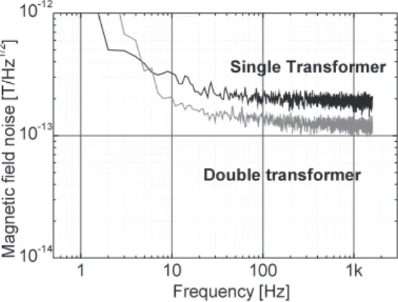
and put the transformer in the hole with vacuum grease. Af-ter the electric wiring, the SQUID was cooled down and the magnetic field noise was evaluated. The spectra of the mag-netic field noise are shown in Fig. 7. The spectra in the case of conventional single transformer are also shown for the comparison. The filed noise is dramatically reduced by a factor of 2/3 and is 200 fT/Hz1/2at 10 Hz.
Then small iron object with a diameter of 30–40μm
were prepared and tested. The samples were put on the con-veyer via a glass slide and magnetized. They were then passed below the SQUIDs with a speed of 15 m/min. The spacing between the object and the SQUID was 2 mm. Fig-ure 8 shows the time trace of the SQUID output signal for
Fig. 6 Double transformer scheme. A liquid 77 K transformer with ra-tion of 1:5 and a second RT transformer of 1:5 were employed so that the total ratio was kept at 1:25.
Fig. 7 Magnetic field spectra of SQUID. In case of double transformer scheme, the filed noise is reduced by a factor of 2/3 and is 200 fT/Hz1/2at 10 Hz as compared with case of single transformer.
Fig. 8 Time trace of the SQUID output signal for iron object with diam-eter of 30–40μm. Distance between object and SQUID is 2 mm.
326
IEICE TRANS. ELECTRON., VOL.E92–C, NO.3 MARCH 2009
an iron test object. The peak-to-peak value corresponds to 30 pT. The noise level is lower than that shown in Fig. 5 and the signal-to-noise ratio S/N is 3, which is allowed lower limit of the actual use in a factory.
5. Conclusion
A contaminant detection system based on high-Tc SQUID
for industrial products was developed. The target foreign particle size for the system was less than 100 micron. A double layered magnetically shielded cylinder with higher shielding factor SF was designed and constructed. The SF of 3850 was achieved by considering the configuration of sleeves at the opening of the cylinders. As a result, we could successfully detect small iron particles of 100 micron in di-ameter with distance of 2 mm. This detection level is diffi-cult to achieve using conventional X-ray detection or other methods. Finally, employing a double transformer scheme at the input circuit, the SQUID noise was reduced by factor of 2/3. Signal from a small iron object with 30–40 μm in diameter was successfully detected with S/N of 3.
Acknowledgments
This work was supported in part by Knowledge Cluster Ini-tiative from Ministry of Education, Culture, Sports, Sci-ence and Technology. The authors are grateful Dr. Tatsuoki
Nagaishi for helpful discussions. The authors thank
Mr. Takeyoshi Ohtani for measurements and helpful discus-sions.
References
[1] M. Uehara and N. Nakamura, “Identification of stable remanence carriers through a magneto-impedance scanning magnetic micro-scope,” Studia Geophysica et Geodaetica, vol.52, p.3, 2008. [2] S. Tanaka, S. Kudo, Y. Hatsukade, T. Nagaishi, K. Nishi, H. Ota, and
S. Suzuki, “High-Tc SQUID metal detection system for food and
pharmaceutical contaminants,” IEICE Trans. Electron., vol.E88-C, no.2, pp.175–179, Feb. 2005.
[3] S. Tanaka, M. Natsume, M. Uchida, N. Hotta, T. Matsuda, Z.A. Spanut, and Y. Hatsukade, “Measurement of a metallic contami-nant in food by high-TcSQUID,” Supercond. Sci. Technol., vol.17,
pp.620–623, 2004.
[4] M. Bick, P. Sullivan, D.L. Tilbrook, J. Du, B. Thorn, R. Binks, C. Sharman, K.E. Leslie, A. Hinsch, K. Macrae, and C.P. Foley, “Metal in food detection: HTS SQUID versus conventional technology,” Extended Abstract of 9th International Superconductive Electronics Conf. (ISEC03), 2003.
[5] G.B. Donaldson, A. Cochran, and D. McKirdy, Fundamentals and Applications, p.599, Kluwer Academic Publishers, 1996.
[6] H.J. Krause, G.I. Panaitov, N. Wolter, D. Lomparski, W. Zander, Y. Zhang, E. Oberdoerffer, D. Wollersheim, and W. Wilke, “Detec-tion of magnetic contamina“Detec-tions in industrial products using HTS SQUIDs,” IEEE Trans. Appl. Supercond., vol.15, no.2, pp.729–732, 2005.
[7] S. Tanaka, H. Fujita, Y. Hatsukade, T. Otani, S. Suzuki, and T. Na-gaishi, “A high TcSQUID micro-detector with a high performance
magnetic shield for industrial products,” Supercond. Sci. Technol., vol.20, pp.S385–S388, 2007.
[8] S. Tanaka, H. Fujita, Y. Hatsukade, T. Nagaishi, K. Nishi, H. Ota, T.
Otani, and S. Suzuki, “A food contaminant detection system based on high-TcSQUIDs,” Supercond. Sci. Technol., vol.19, pp.S280–
S283, 2006.
[9] S. Tanaka, O. Yamazaki, R. Shimizu, and Y. Saito,
“High-Tc SQUID microscope with sample chamber,” Supercond. Sci.
Technol., vol.12, pp.809–812, 1999.
[10] B. Muhlfelder, W. Johnson, and M.W. Cromar, “Double trans-former coupling to a very low noise SQUID,” IEEE Trans. Magn., vol.MAG-19, no.3, pp.303–307, 1983.
Saburo Tanaka received his B.E. and M.E. from Toyohashi University of Technology in 1981, and 1983, respectively. He received his Doctoral Degree in engineering from Osaka University in 1991. Since 1987 he has been in-volved in the research of high-temperature su-perconductors at Sumitomo Electric Itami Re-search Lab. He was engaged in the development of multichannel high-TcSQUID systems at the
Superconducting Sensor Laboratory from 1991 to 1995. He was a visiting research associate at the Department of Physics, University of California at Berkeley from 1996 to 1997. Currently, he is a professor, a presidential advisor and a director of the Research Center for Future Technology at Toyohashi University of Technology. He is a member of the Japan Society of Applied Physics, the Institute of Electrical Engineers of Japan, and the Institute of Electrostatics Japan.
Tomonori Akai received the B.E. degree in Ecological Engineering from Toyohashi Uni-versity of Technology in 2008. At present, he is studying toward M.E. degree at the graduate school. His research interest is a detection sys-tem using high TcSQUID. He is a member of
the Japan Society of Applied Physics.
Yoshimi Hatsukade received his B.E. and M.E. from Waseda University in 1998 and 2000, respectively. He received his Doctoral De-gree in engineering from Waseda University in 2003. Since 1998 he has been engaged in the research of nondestructive evaluation technique using SQUIDs for conductive materials. Cur-rently he is an assistant professor at Toyohashi University of Technology. He is a member of the Japan Society of Applied Physics, and the Cryogenic Association of Japan.
Shuichi Suzuki received the B.S. degree in Mechanical Engineering from Shinshu Uni-versity in 1964. He joined Mitsubishi Rayon Co., Ltd. in 1964. Then he moved to Mitsubishi Rayon Engineering Co., Ltd. in 1975. Since 1964, he has been involved in a plant construc-tion projects. He established Japan Intercool Co., Ltd. in 1995 and Advance Food Technol-ogy Co., Ltd. in 1997 respectively. Currently he is a president of Advance Food Technology Co., Ltd.