Rarefied
gas
flows induced
by temperature
fields and their
applications
京大・工・航空宇宙 杉元 宏 (HiroshiSugimoto)
Departmentof Aeronautics andAstronautics,
Graduate School ofengineering, Kyoto University
Thispaper consistsoftwo parts. Inthefirst$P^{aI}t$wepresent theresult of the numerical simulation
onthe steadygasflowinapump driven by thermal edgeflow, whichi8proposed inRarefiedGas Dynmics,AIP,NewYork, 138-141 (2002). Anewfindingof thisanalysisisthepossibility ofthe
alternativedesign of the flow channelofthepump. According to thenewdesign ofthechannel, a rarefied gasflow is inducedthroughapair of parallel wire meshes with differenttemperatures. In
the secondpartofthispaper,weconflrmthuis phenomena by simpleexperiments.
1
Introduction
In
a
rarefiedgas,
where themean
ftee path of thegas
molecule is not negligible com-paredwith the scale ofthe system, the temperature field ofthegas
is deeply relatedto thegas
motion. The flow of therarefiedgas
is induced by the temperature flelds ofthegas
even
ifthereisno
extemal force. The thermal transpiration flow1,2) whichisa
flowinducedin
a
pipewitha
temperature gradient alongit, isawell known example, andnow
it is known that various flows with different properties
are
induced by the temperaturefields.3)Thethermaltranspiration flowin
a
pipesuggestsa
possibility ofa
Pumpwithout moving parts. That is, ifwe
connect two tanks of different temperatures bya
thin pipe ofa
uniforncross
section, the thernaltranspiration flowis inducedin thepipe and thuswe
can
maintaina pressure
difference between these tanks. However the difference ofthe pressure between the tanks is proportional to the temperature difference. Thus this
simple idea isnot practical since the variations of temperature of material is rather
lim-ited than that of
pressure
of thegas.
In 1910, Knudsen camied outan
experiment bya
single pipewith periodic variations of diameter and$temperatu\infty$ (Fig. 1), and succeededto obtain the
pressuoe
ratio 10, which is fairly larger than the temperature ratio in the system.4) Recently this type ofpumps
driven by temperature field attracts researchersagain, since it does not require moving parts and has
a
possibility of the applicationas
microdevices.5-14)
Theauthor andSone havebeen camied out twoexperimentsofthe
pumps
driven by the flows induced by the temperature field. Thefirstone
is thepump
driven by thethermaltranspiration flow.10) (This type of
pump
is called “Knudsen compressor’‘ now.) The experiment showedthatitcan
reduce thepressure
ofa
tank of8 litertoa
half in300 $sec$,butits
energy
efficiencyislower thanstandard commercialpump
byfar. Thispump
isvery
primitiveand
many
improvementsare
required. Oneof thereason
of the low efficiency ofthe Knudsen
compressor
isthe temperaturegradientofthepipe wall whichis essentialtothe thermal transpiration flow. Thatis,
a
heatfluxthrougha
pipewall,whichis theloss ofthe
energy,
isrequired tomaintainthe temperature gradient. Inordertoreducethis loss ofchannelofthe
pump
isrequired. As for the Knudsencompressor,
thereare some
amountsof works. The corresponding analysis for the thermal edge
compressor
is
recentlypublished inJapanese13). Inthe presentPaper, themain resultsofthe Paperandthe
new
results
on
the altemative design of the thermal edgecompressor
are
presented in Sec. 3.The result
on
thealtemativedesignis uniquesinceitshowsthata new
typeofrarefiedgas
flow is induced through
a
pairof parallel wire meshes with differenttemperature. Inthenext partof this
paper,
Sec. 4, theresultsof twopreliminaryexperimentson
theexistenceofthe flow through
a
pair ofwiremeshesare
reported.2
Thermal Edge Compressor
Thethermal edge
compressor
consistsofa
number ofdrivingunitsconnectedinseries,as
wellas
the Knudsencompressor.
Figure 3showsan
$2D$model of theunit
of the thermaledge
compressor
devised in Ref. 12. The channel is equipped witha
pair oftwoarrays
of plates,
one
isheated (temperature $T_{h}$) and the otherisunheated(temperature$T_{c}$). Thesize ofthe unit in$X_{1}$ direction$D_{w}$ is largerthan the totalwidthofthe setof
arrays
oftheplates, thus
some
space
is left around the set ofarrays
ofthe plates. The mechanism ofthisunitis
as
follows. In theoverlapping regionofthetwo arraysof plates,a
temperaturegradient in $X_{1}$ direction is induced. This temperature gradient induces the thermal edge
flow in $X_{1}$ direction. In the
gas
region around other edges of each plate, the temperatureofthegas isroughly uniform since there arelots of plates of identicaltemperature in$X_{2}$
direction in
a space
left aroundthearray.
Therefore the thermal edgeflow induced thereis weaker than those induced in the overlapping region. In the
narrow
regions betweentheplates of each
array,
the flow isnotinducedsincethe temperatureof thegas
isroughlyFlg.1: Theexperimental apparatus by Knudsen(Ref. 4). The diameter of the thin partis0.$4mm$
and that of thicker part is $10mm$, and the temperature difference between the heated part and unheatedpartisabout$500K$
.
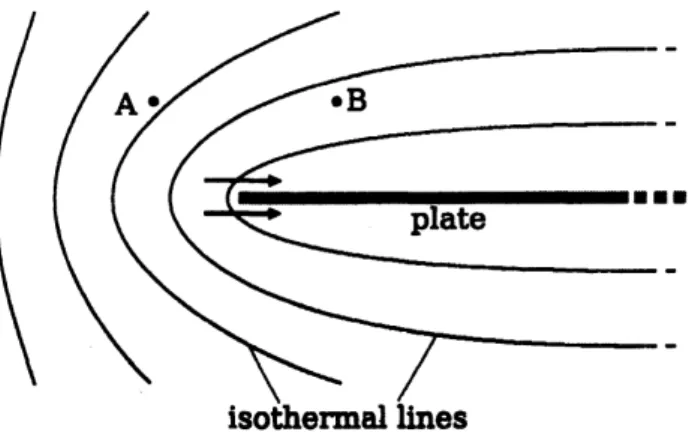
Fig. 2: Thernal edge flow. The points A and $B$ are about
one mean
free path away from theedgeof the plate. Near the edge, the isothermal linesaresharplycurved,and thusthe temperature
is non-uniform along the plate. The molecules impinging
on
the edge region from theleft sideareroughlyrepresented bythosefrom A and the molecules from the right side bythosefrom$B$,
wherethegas ishotter than at A when the plateisheated. The situationis similartothat
over
a non-unifornly heatedplate, where the thernalcreepflow1)is induced. Thus,aflowis inducedinthe directionofthearrowsaround theedgeofaheated plate.
Fig.3: Aunit ofthermaledgecompressor.
uniformthere. In
summary,
theflowismainly inducedinthe overlapping regionbetweentheheated
array
and unheatedarray.
Thusthis unitinducesa gas
flowin$X_{1}$ direction.3
Numerical
simulation
Wecarryout two
cases
ofnumerical simulationon
theflows in the thermal edgecom-pressor,
following thenumerical analysison
thegas
flowsin theKnudsencompressor
inRefs.
6
and7.
Problem-I: Investigatethe maximumflow rateobtained by thethermal edge
compressor.
The maximum flow rate here is the flow rate obtained when the
pressures
of thegas
atthebothendsof the system
are
closed by the walls.The shape of the flow channel of thermal edge
compressor
israther complicated, thusthere
are
many
parameterson
it. Thepurpose
of thispaper
isnotthe optimization of these parameters, buttoshow the basic properties ofthethermal edgecompressor.
Furthermore the resultsgivenin Sec.3.$3B$will showthat the design of theflow channelis not restrictedtothe
one
shownin Fig.3. Thereforewe
firstrestrictourselvestothechannelshape shownin Fig. 3, and omit the explanation ofdetailed shape
on
it. Weuse
only the followingparameters ofthe
compressor
unit in thispaper.
$T_{h},$ $T_{c}$:
the temperatuoe of twoarrays
ofplates (the temperature of side wall is also $T_{c}$)$;D_{h}$
:
thedistance berweenthe plates ina
array;
$n$:
the number of plates with temperature$T_{h}$ (orthe number of small flowchannelsof height$D_{h}$),$D_{w}$; thelengthof
a
unitin$X_{1}$ direction.3.1
Basic Equation
The analysis is carried out
on
the basis of the Boltzmann equation for hard sphere molecules:17)$\xi_{1}\frac{\partial f}{\partial X_{1}}+\xi_{2}\frac{\partial f}{\partial X_{2}}=J(f.f)$, (1)
$J(f,f)= \frac{d_{m}^{2}}{2m}\int_{\kappa.|<\infty.\psi|--1}[f(f_{*})g(\xi’)-f(\xi.)g(\xi)]|V\cdot a|d\Omega(a)oe_{*\prime}$ (2) $\xi’=\xi+(V\cdot a)a$, $\xi_{*}’=\xi$
.
$-(V\cdot a)a$.
$V=\xi$.
$-\xi$.
(3)The notation is
as
follows. $d_{m}$:
the diameter ofa
molecule; $m$; themass
ofa
molecule;$\xi_{i}$
:
the molecular velocity; $f$:
velocity distribution function ofgas
molecules; $dg$.
$=$ $d\xi_{1}d\xi_{2}d\xi_{3};d\Omega(a)$:
solid angle elementinthe direction ofunit vector$a$.
Theboundarycondition
on
solid walls isthediffusereflection:$f( \xi\cdot n>0)=\frac{\sigma_{w}}{(2\pi RT_{w})^{3/2}}\exp(-\frac{|\xi|^{2}}{2RT_{w}})$, (4)
where$T_{w}$and $n$are,respectively, the temperatureandtheunit normalvectortothe
bound-$a\iota\gamma$, pointed to the
gas.
$R$ is the specificgas
constant ($R=k_{B}/m,$ $k_{\beta}$:
the Boltzmannconstant). Inthe numerical simulationthe specular reflectioncondition
$f(\xi\cdot n>0)=f(\xi-2(\xi\cdot n)n)$, (6)
is alsousedto represent
a
symmetric surface.The macroscopic quantities
are
defined by the moments of the velocity distributionfunction$f$
as
follows:$\rho=\int fdg$, $\nu=\frac{1}{\rho}\int\xi foe$, $T= \frac{1}{3w}\int g_{-\nu|^{2}foe}$
.
$p=R\rho T$, (7)where$\rho,$ $\nu,$ $T$, and$p$
are
the density, flowvelocity, temperatureandpressure
ofthegas,
respecuvely. The
integrations
are
camiedoutover
thewholespace
of$\xi$.
An important length of scalein the Boltzmann equation is the
mean
free path ofthegas
molecule. Forhard spheremolecules, its sizeat equilibriumstate at rest$de\mu nds$on
$d_{m},$ $m$, and density of the
gas.
Thuswe
deflne the referencemean
free path $\ell_{a\nu}$ by usingthe
average
densityover
a
period (Problem-l,or average
densityover
thepump
system (Pmblem-Il).Thatis,$\ell_{av}=m/(\sqrt{2}\pi d_{m}^{2}\rho_{av})$
.
(8)TheKnudsennumberKnisdefined by
$Kn=t_{a\nu}/D_{h}$
.
(9)For theconvenienceof thedescription
we
introduce referencepressure
$Po$by$p_{0}=R\rho_{a\nu}T_{c}$
.
(10)3.2
Method of solution
The system ofequation(1)$-(6)$isanalyzed numerically by theDirectSimulationMonte
Carlo (DSMC) method18) where the gas molecules
are
replaced bya
numbers ofsimu-lation particles, and the behaviorof the particles
over a
small time step is simulated bytwo separate
processes,
theprocess
ofmotionof the particles withoutcollisions andtheprocess
ofchanging their velocities bycollisionsbetween particles. Thus the method is$ume$-dependent. We obtained the steady solution of Pmblem-I
or
Problem-IIby chasinga
long time behavior of the results. The DSMC method is widely used in the studies of rarefiedgas
flows, and the numerical procedureused here is just thesame
as
theone
describedin Ref.6.
What is specialin thispaper
is only thatthe shape of the flow fieldis rather complicated by
many
pieces of plates. The DSMC method is convenient forthis type ofthe problems since
we
can
divide the flow fieldintomany
small rectangular domainsbyintroducingvirtualboundariesin thegasregion. Wecarry
outthenumerical simulation in each rectangular domain by using additional boundary conditionson
the(a) (b)
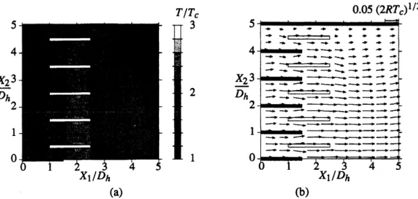
Fig. 4: One way flow in thethermal edge compressorI (Problem I). $T_{h}/T_{c}=3.n=10$, and
Kn $=1$
.
$(a)$Temperature fieldand (b): flow velocity field. The temperature field in(a)isshownbytheshadeof thedarkness, and itsscaleisshown intheright end ofthepanel. The
arrows
in(b)indicate the flow velocity attheir starting points,whose scaleisshown
on
the rightshoulderof thepanel.
from the virtual boundary ofcorresponding adjacent domain. This methodis also effec-tive for parallel computers since
we
can
carry
out the simulationforeach domainalmostindependentlyexcept small amount of information
on
the molecules thatpass thevirtualboundaries ineachtimestep ofnumerical simulation.
3.3
Results
A One
way
flowfor basic channelHere
we
explainthe result forProblem-I, themaximumflow rateobtainedby the ther-mal edgecompressor.
Figure4showsthe temperature and flow velocity fields for thecase
of$T_{h}/T_{c}=3$, Kn $=1$, and$n=10$
.
Onlythepart$X_{2}>0$ is analyzed sincethe system issymmetricwithrespect to$X_{2}=0$, andthecyclic boundary condition isappliedto$X_{1}=0$
and $5D_{h}$
.
The temperature gradiem is large in the gas at the overlappingregion oftwoarrays
of plates $(D_{h}\leq X_{1}\leq 1.5D_{h})$.
On theotherhand, the temperature gradient issmallaround the other ends ofplates($X_{1}\sim 0,2.5D_{h}$
or
$5D_{h}$). As theresult, theone-way
flowis induced in$X_{1}$ direction. The flow spoed$v_{1}$ decreases
near
the side wall at$X_{2}=5D_{h}$.
This isbecause ofthe temperature betweenthe sidewall and the nearest plate (theplate
at$X_{2}=4.5D_{h}$) isroughly symmetric withrespectto$X_{1}$ direction, andonly
a
small size ofnetflow$v_{1}$ is inducedthere.
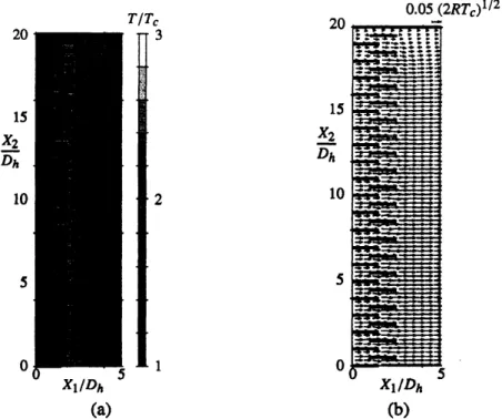
Figure 5 shows theone-way flow for the
case
of$T_{h}/T_{c}=3$, Kn $=1$, and$n=W$.
Theeffect of side wall at$X_{2}=nD_{h}/2$ is confined in several small channels (or several $D_{h}$in
$X_{2}$ direction)
near
the side wall, anda
periodic structure oftheflow fieldin $X_{2}$ direction(a) (b)
Fig.5: One way flow in the thermal edge compressorII (Problem$I$). $T_{h}/T_{c}=3,n=40$, and
Kn$=1$
.
$(a)$Temperaturefield and(b): flow velocity field. (Seethecaptionof Fig.4).fig. 6: A simpler model ofa unit of the thermal edge compressor. $X_{2}=0$ and $D_{h}/2$ are the
symmetric surface. The part-Crepresentstheunheated plate, and pan-H does the heated wall.
This resultleads
a
simplified model ofthethermal edgecompressor
depicted in Fig.6.Consider
a
rectangular domain$0<X_{1}<D_{w}$and$0<X_{2}<D_{h}/2$.
The boundary conditionat
a
part of the lower boundary $X_{2}=0$ (say, part-C in Fig. 6) is the diffuse reflection (4) attemperature $T_{c}$, anda
part oftheupper
boundary$X_{2}=D_{h}/2$ (part-Hin Fig. 6) isthe diffuse reflection at temperature $T_{h}$
.
The boundary condition at other partofupper
and lower boundary is the specular reflection (6). The condition for boundaries normal
to$X_{1}$ direction will bedefined depending
on
thepurpose
of the problems; In this section(P’vblem-b),
we
apply the cyclic boundary condition. This modelis denoted by$narrow\infty$fortheconvenience ofexpression.
Flg. 7: Nondimensional
mass
flow rate percross
sectionalarea
$m_{f}/\rho_{av}(2RT_{c})^{1/2}$vs
KnudsennumberKnof the thermaledgePump (Problem-l). $T_{h}/T_{c}=3$
.
$x:n=10,2:n=20,$ $\theta:n=40$,$\bullet;narrow\infty$
.
flux
per
unittimeandper
unitarea
ofthecross
sectionofthecompressor
unit$m_{f}=\{\begin{array}{ll}\frac{2}{nD_{h}}\int_{0}^{D_{h}/2}\rho v_{1}dX_{2} (n<\infty),\frac{2}{D_{h}}\int_{0}^{D_{h}/2}\rho v_{1}dX_{2}1 (narrow\infty),\end{array}$ (11)
are
plotted forKnudsennumberKn $=0.01,0.5,0.2,0.5,1,5$, and 10for$n=10$and $\infty$,and Kn $=1$ for $n=20$ and
40.
The nondimensionalmass
flux $m_{f}/\rho_{0}(2RT_{c})^{1\prime 2}$ takes itsmaximum value around Kn – 0.5, and it decreases
as
$Knarrow 0$or
$\infty$.
The effect oftheside wall is clearly
seen
in thecases
for $n=10.20,40$, and $\infty$ at Kn $=1$.
Themass
flux approaches to that for$narrow\infty$
as
$n$ increases and the deviation of$m_{f}$ fromthecase
of$narrow\infty$ is roughly proportional to $1/n$
.
This supports the previous discussion that theeffectof sidewall isconfined in
a
smallregionnear
the sidewall.B Alternativedesignofflow channel
The preceding result shows that the velocity ofthe
one-way
flow (which is roughly representedby $m_{f}/\rho_{av}$) in the thermal edgecompressor
takes its maximumvalue whenthe scaleof thesmall flow channel$(D_{h})$iscomparableto the
mean
freepath$\ell_{a\nu}$ of thegas
molecules. The $p_{a\nu}$ athigh
pressure
is, however, quite small [cf. Eq. (8). $\ell_{av}\sim 0.07\mu m$ under the atnosphericpressure
and the standardtemperature], and itcan
be difficulttorealize
a
complicated flow channels by the usualengineering process. Herewe
investigate the possibility of altemative design of flow channel of the thermal edgecompressor.
In the following numerical analysis,
we
arrange
objects ofvarious $sha\mu$ in the flowchannel, and the
gas
region is not represenoed only by $X_{1}=$ Constor
$X_{2}=$ Const. Inthis
paper
such shapes ofgas
region is also approximately represented by the union ofincrease of computational time, since, in
some
cases,we
have toprepare
large number of rectangularregionsto represent the shape of the boundary. Thereforewe
carryout thenumerical simulation onlyfor thelimiting
case
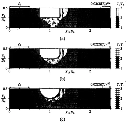
formany smallflowchannels ($narrow\infty$ in Sec.A).Some of the results
are
shown in Fig.8.
Inthe figures, the temperature fieldis shown by the shade of the darkness and flow velocity is represented byarrows.
In thecase
ofFig.8(a), two
squares
withone
side$\ell_{av}$ in lengthare
put in thechannel. Thetemperatureof square at smaller$X_{1}$ is $T_{c}$, and that of larger $X_{1}$ is $T_{h}$
.
In thiscase
the temperaturefield around each
square
is slightlyasymmetricwith respect to$X_{1}$ direction,andone-way
flowis inducedin$X_{1}$ direction. The
mass
flux$m_{f}$per
unitarea
ofthecross
sectionof thecompressor unitl
is$m_{f}/\rho_{av}(2RT_{c})^{1/2}=0.\omega 32$.
Themass
flux$m_{f}$ increases ifwe
roundoff the edges of thesesquares. In the
case
ofFig. 8(b), the radius ofthe curvatureis$l_{av}/4$ and$m_{f}/\rho_{0}(2RT_{c})^{1/2}=0.\alpha)43$.
In Fig. 8(c), the objectis cylinder with radius$\ell_{a\nu}/2$, and$m_{f}/\rho_{0}(2RT_{c})^{1/2}=0.\infty 53$
.
In Fig. 8(c), the objects put in the channel
are
the circular cylinders, and thus there isno
“sharp edge” ofa
solid body which is usuallyrequiredto induce the thermal edgeflow. Of
course
thereisno
thermaledgeflow arounda
circular cylinder put isolatedfromotherboundaries. Inthe
case
ofFig. 8(c),we
are
considering thebehaviorofthegas ina
compressor
unit whichconsistsoftwoparallelmeshes withdifferent$tem_{K^{ratu\infty S}}$, sincethe boundaries$X_{2}=0$ and$D_{h}/2$
are
the symmetric surface. Thesetwo meshesinducea
temperature gradient ofthegas in$X_{1}$ direction between these meshes. This temperature
gradient induces
a
one
way
flow similar to thoseseen
in the thermal edgecompressor,
because the size of the wires and distancebetween the meshes
are
ofthe order of themean
free pathofthegas
molecules$\ell_{av}$ ($=D_{h}/2$inFig. 8).Asis discussed inSec.$A$,thewidth of the smallchannelofthethermaledge
compressor
would be of the order of the
mean
freepath of thegas
molecules$\ell_{av}$.
Fromthe resultinthis section, it is possible to infer that
one-way
flowsare
induced byany
object witha
radius ofcurvature of the order of$\ell_{av}$
.
These two informationsmeans
thatone can use
various $\mu rous$ materials with pole size of$t_{av}$ to constructthe thermal edge
compressor
unit. From theviewpoint ofengineering, it is importantresult whichenablesthethermal
edge
compressors
withmicrochannels worksathigherpressure
ofgases.
CPump effect
Next
we
considerProblem-lI, the steadypressure
distribution ina pump
systemcon-sisting of
a
number ofcompressor
units connected in series with their two ends ofthePumpsystem beingclosedbythe walls. The number of the
compressor
units$N$islimitedin the DSMC simulation. The accuracy and computational speed of DSMC dcpend
on
thenumberdensity of simulation particles, whichshow unbalanced distributionas
$N$in-creases
inthis problem. Thisresultsinthe lowaccuracy
atlowdensityregions andalow1Amodiflcationofthedomainof integrationinthedefinition of$m_{f}$in(11)isrequiredsincesomepart
of the domain of integrationcanbeinsidethe solidbody. Theintegrationhereiscarriedoutonlyinthegas region.
(c)
Fig.8: Oneway flow inthe thermal edgecompressor$b$ (Problem 7). $T_{h}/T_{c}=3$
.
$(a)$ Thecasewhere theplates arereplaced with squareboxes with temperature $T_{c}$ (shownby
a
darkbox) and$T_{h}$ (shown by blight box); (b) Thecase with square boxes with the round off(theradius of the
curvature is $D_{h}/4$); and (c) The
case
with a cylinder with diameter $D_{h}/2$.
(See thecapuon
ofFig.4.) Thesizeof the reference
mean
freepath$t_{av}$isshownonthe leftshoulderofeach panel.computational speed athigh densityregions. In Ref. 6, itis shown that thecompression
ratio ofa
compressor
unit isa
functionof the local Knudsen number$Kn_{L}$ defined bytheaverage
density of thegas
in each unit in the system, and theirrelation is determinedas
follows: (i) Carry out the numerical simulation with $N=10$ for Knudsen number Kn defined by the density$\rho_{av}$ of the
gas
averagedover
wholePump system;(ii) Obtaina
partoftherelation between thecompression ratio and $Kn_{L}$ from the result of(i); (iii)Repeat
(i) and(ii)forvarious Kn. In thisPaper,
we
follow this method. We also considera
pumpsystem of 10
compressor
units of basictype shown inFigs. 3or
6, and theboth ends of thePump systemare
closed by the walls with temperature$T_{c}$.
Wefirst define thepressure
averaged
over
thecross
sectionofthepump
$p(X_{1})$by$K_{1}\Phi_{i}$
(a) (b)
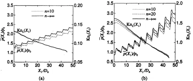
Fig.9: Thedistribution of theaverage poessure$\overline{p}(X_{1})$ and local Knudsen number$Kn_{L}(X_{1})$in the
steady state of
a
closed system of10 compressorunits(Problem II).$T_{h}/T_{c}=3$.
$\cdots\cdots\cdots$ :$n=10$,–$\cdot$ –: $n=20$,–: $narrow\infty$
.
$(a)Kn=0.1,$$(b)Kn=1$.
(a) (b)
Fig.10: Thecompression ratioofacompressorunit$P(X_{1})$vsthe local Knudsen number$Kn_{L}(X_{1})$
(Problem II. $T_{h}/T_{c}=3$
.
$(a)n=10,$ $O$: Kn $=$ 0.1,0.4, 2, 5; $\bullet$: 0.2, 1,3.5. (b) $narrow\infty,$ $O$:Kn $=0.05,0.1$,0.3,0.75, 1.5, 2.75, 4; $\bullet$: 0.075,0.2, 0.4, 1, 2,3.5. Theranges oflocal Knudsen
number $Kn_{L}(X_{1})$ for each value of Kn are shown in the bottom of the figure. The white line
representstheapproximationcurveEq. (15).
Thecompressionratio$P(X_{1})$of
a
compressor
unitbetween$X_{1}$ and$X_{1}+D_{w}$isdefinedby$P(X_{1})=\overline{p}(X_{1}+D_{w})/\overline{p}(X_{1})$, (13)
and the local Knudsennumber$Kn_{L}(X_{1})$by
$Kn_{L}(X_{1})=\frac{m}{\sqrt{2}\pi d_{m}^{2}\overline{\rho}(X_{1})D_{h}}=\frac{\rho_{av}}{\overline{\rho}(X_{1})}Kn$, (14)
where$\overline{\rho}(X_{1})$ isthe
average
densitybetween$X_{1}$ and$X_{1}+D_{w}$.
The examples of the distribution ofthe
average
pressure
$\overline{p}(X_{1})$ and thelocal KnudsenFlg.11: Thecompressionratio$\Pi_{N}$obtained by$Ncomp\infty ssor$units (Problem II).$T_{h}/T_{c}=3.narrow$
$\infty,$$Kn_{L(1)}=5.7$
.
The marks $\bullet$ show the points$(i,\Pi_{i})$where$Kn_{I4^{i)}}\sim 0.05$,0.1,0.2,0.5, 1, 2,3.5.pressure
$\overline{p}(X_{1})$ increases showingsome
vibrationsas
$X_{1}$ increases. The profile of localKnudsen number $Kn_{L}(X_{1})$ is smoother than that of$\overline{p}(X_{1})$
.
Itis because $Kn_{L}$ is definedby the
average
densityover
a
unit length $D_{w}$ and $\overline{p}(X_{1})$ by the values ata
cross
sectionat$X_{1}$
.
The profile of$Kn_{L}$ shows local variations atboth endsof thepump
system. Thiscorresponds totheeffect of end walls of the
pump
systemwhichis alsoseen
inRef. 6.The sets of$(Kn_{L}(X_{1}),P(X_{1}))$ for various Knudsen numbers Kn
are
plotted in $Kn_{L}-P$ plane for thecase
$T_{h}/T_{c}=3$ and $n=10$ and $\infty$ in Fig. 10. Thepoints $(Kn_{L},P)$ forma
curve
$P’(Kn_{L})$ in the $Kn_{L}-P$plane. The data for$X_{1}$near
the ends of the Pump systemdeviate from the above
curve
$P’(Kn_{L})$due tothe effect of the end walls ofthe system. An $aPproXimanon$of$P(Kn_{L})$:
$P’(x)\sim$
exp
$[C_{0}+C_{1}\ln x+C_{2}(\ln x)^{2}]+1$, $C_{i}$ : Constant, (15)is also shown in the figure, where $C_{i}$
are
determined by the leastsquare
method fromthe data $(Kn_{L},P)$ except those close to the ends of the Pump system. The values of$C_{l}$
are
$(C_{0}, C_{1},C_{2})=(-2.24, -0.276, - 0.244)$ for $n=10$ and $(-2.11, -0.221. - 0.238)$ for $narrow\infty$.
The compression ratio $\Pi_{N}$ of
a
Pump system consists of$N$unitscan
be estimatedbyusingEq. (15). Thatis,
we
estimatethe local Knudsen number$Kn_{I40}$ ofi-thunit and the total compressionratioof thesystem $\Pi_{N}$ froma
initiallocal Knudsen numberati-thunitby
$Kn_{L\langle i+1)}=Kn_{L(i)}/P(Kn_{L\langle l)})$, $\Pi_{N}=\prod_{i\overline{-}1}^{N}P(Kn_{L(l)})$
.
(16)An example of the resultis shown in Fig. 11,for the
case
of$T_{h}/T_{c}=3$ and$n\cdotarrow\infty$ with(a) (b) (c)
Fig. 12: The device that forns a flow channel ofthe scale of lmm. (a) Unheated part. It is a
rectangular copperplate (thickness lmm) of200mm in height and 200mm in width. There isa rectangularhole of80mm in widthand 100mmin height. A large numberofcopper wires with diameter lmmisattached in thehorizontal directiontothe hole with the solder. (b)Heatedpart.
An aluminum frame forms a square flow channel of side 100mmin length. A large number of Kanthal heater wires with diameter lmm invertical direction areattached by alumina adhesive
on
onesideof theframe. (c)The assembled device. The wires aroundtheheatedpartsupply the electric current totheheaterwire.4
Experiment
In the
course
ofthenumericalsimulationin Sec.3,a one-way
flowunder thecondition ofperiodic flow along thepump
system (Pmblem-I) is induced by the newly designedunit,whichconsistsof
a
pair of parallelwiremeshes with differenttemperatures. Itmeans
that there will bea
rarefiedgas
flow througha
pair of parallel wire meshes withdifferent temperatures. The flow is, however,notfoundinliterature. Therefore,we
wincarry
outa
preliminaryexperiment inthissectiontoobserve this phenomenaina
rarefiedgas.
4.1
Experinent
on
the channel width of
lmm
A Experimentalapparatus
Here
we
presentthe setup for theexperimentof the channel width of lmm. The device consistsoftwoparts:one
isthe unheated part, and the other is the heated part. Thefomeris
a
rectangularcoPperplate (thickness lmm) of$200m\iota n$inheightand 190mm in width.This plate has
a
hole of 100mm
in height and 80mm in width [Fig. 1$2(a)$], andmany
copper
wires with diameter lmm in horizontal directionare
arranged in the hole. The latterisa
aluminum frame[Fig. $12(b)$]whichformsa
square
flow channel of side $1\infty\iota nm$in length, and
many
Kanthal heater wires with diameter lmm in vertical directionare
attached by alumina adhesive. Thegap
between eachof thesewires,$cop\mu r$andKhantal,is about lmm.
The aluminum frameishung
on
thecopper
plate by several Nylonsuppon
partsso
that the side ofthe mesh of heater wire faceto the wire meshon
thecopper
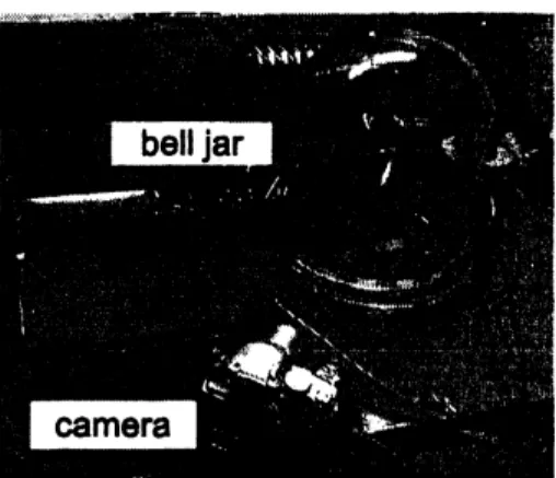
plate. Thedis-Fig. 13: The overviewofthe experimental apparatus. The deviceis setinside the glass belljar. Themotionof the filmorwindmillisobserved by thecamerapositioned appropriately.
(a) (b)
Flg. 14: (a) Wlndmill to detect the vertical gas flow. The
vane
is made of mica. Thevane
is supported byabearing oftinyglasscupandasteelneedle. (b)The aluminum duct andahole forthewindmmill, attached to the unheated side ofthe device. Thewindmilldetects upward flow ifa
gasflowsthrough the device from unheated side to heated side.
tance between thesewiremeshes is kept
as
closeas
possible, while thereisa
smallspace
between them. (We
can
detect thecontactbetween them by measuningthe electricresis-tance.) Then thewhole systemisputin
a
glassbelljar, whoseinnerpressure
iscontrolledfromthe atnospheric
pressure
($1.01\cross 10^{5}$Pa)down to about0.5 Pa byextemal oil-sealedvacuum pump
(Fig. 13). The coPperplate ofthe unheatedpan
is connected to the steelbase of the
vacuum
chamber to keepthetemperatureclose to theroom
temperature.We supply the electric current to the heater wire with the
gas pressure
$p$ in the belljar being kept at
some
constant value. Thenthegas
flow through thispair ofwiresare
detected by two separate experiments: (A) A thin aluminum film (thickness $4\mu m$) of
width
60mm
andheight80mm ishungon
the flowchannel inthe side of theheatedwire.We observe the motion ofthe film by
a
camera
(Fig. 13); (B) Preparea
windmill whichdetects
a
flow in the vertical direction[Fig. $14(a)$]. The windmill is set inan
aluminum ductattachedtothe hole ofunheatedcopper
platein the opposite sideofthe heatedmesh(a) (b) (c)
Fig. 15: The movement ofthe film in experiment (A) for the case ofchannel width of lmm. I: The results forconstantpressure$p=1Pa$ and variousenergysupply $E$to the heater. (a) $E=OW$,
(b)5.$2W,$ $(c)12W$,and(d)$21W$
.
after the heaterisput
on
in ordertowaitthe steadytemperature of the device. B Res\omega 籾Two series of experiments
are
camied out for experiment (A). In the first serieswe
observe the film forvarious
energy
to the heater $E=0,5.2,12$, and 21W with keepingconstant
gas pressure
$p=$ 1Pa. The result is shown in Fig.15.
The film is graduallyinclined
as
theenergy
$E$ to the heater increases, and keeps atsome
angleas
longas
$E$and$p$
are
kept atconstant value. The temperatures of the frame ofthe heated part andthat ofthe
copper
plate of the unheatedpartare
measuredina
separateexperiment. Thetemperature difference between themis 0.OK at $E=OW,$ $6.6K$ at2.$0W,$ $11.4K$ at4.$0W$,
and
19.
$8K$ at8.
$5W$.
In the second series theenergy
to the heater $E$ is fixedto $21W$, and theobservationiscamiedoutforvarious $p$intherange
from 1Pato$2\ovalbox{\tt\small REJECT} Pa$.
Some oftheresults
are
shown inFig.16.
Themovementof thefilmtakes maximumvalue ataround$5Pa$,where the
mean
free pathoftheairisabout lmm. Themovementofthefilm vanishesas
pressure
increases. In this preliminary experiment it is difficult toconclude that this shows that the flow vanishesas
Knudsen number decreases; We will discuss about theproblem laterin Sec.4.3.
The experiment (B) is camied out for the
case
with $(E,p)=(0W, 5Pa),$ $(2W, 5Pa)$,$(18W, 5Pa),$ $(18W, 20Pa)$, and($18W,$ lmpa). There is
no
rotationof thewindmill for thecase
of(OW,$5Pa$)or
$(18W. 100Pa)$.
For othercases,thewindmill rotates andthedirectionof therotationshows that the
gas
flowisupward. Fromthepositionof the windmill showninFig. 14(b), it
means
thatthegas
flows through thepair ofwire meshes from unheated wiremeshtoheatedwiremesh. Therotationspeed of the windmillis 95rpmat$(2W, 5Pa)$,667rpmat$(18W, 5Pa)$, and 176rpmat $(18W, 20Pa)$
.
4.2
Experiment
on
the
channel width
of
$100\mu m$A Experimentalapparatus
In order to confirmthe applicability ofthe flows induced through thewire meshes to
(a) $\zeta b$)
Mg. 17: Experimental setup for the exporiment of flow channel of $1\infty\mu m$ in width. (a) The
stainless mesh. The scale of 100pm is shown at theright bottom
comer
of the figure. (b) The schematic figure (not to scale) of the device for the experiment. This figure shows thecross
sectionalongtheflow channel to explain the layered sbuctureof thedevice.
mesh size is about $10\mu m$ [Fig. $17(a)$]. Inthis
case we
have tosuPpontwo wire mesheswith differenttemperaturesin
a
smalldistance. For thispurpose we
constructed alayeredstructure
as
shown inFig. 17(b). Thebaseisa
copperplate A (thickness$20mn$) witha
circular hole whichis
one
end oftheflow channel [Fig. $17(b)$]. The diameter oftheholeis 10mm
on
one
side andit is enlargedto20mmon
theother side. This plateisconnected toa
biggercopper
basewhichisconnectedtothesteelbaseofa
vacuum
chamberto$k\infty p$the$tem\mu rature$ closeto the
room
temprature[the coPperbase is omitted in Fig. $17(b)$]. In order to support two wire meshes, the following material is layeredon
thiscopper
plate: (i) A stainless wire mesh B. (ii) Several mica plates $C$ (thickness $20\mu m$). whichforms
a space
around the hole ofthecopper
plate A. (iii) Another stainless wire mesh $D$, to whichtwoof electricalleads, shown bya
dotted lines inFig. 17(b),are
attachedtosuPply
an
electric currentto the mesh. (iv) A mica plate $E$ (thickness $2\ovalbox{\tt\small REJECT}\mu m$). $(v)$ Aaluminum plate $F$(thickness $10mm$) with
a
hole whose size is similarto thaton
$\bm{m}p\mu r$plate A. The main
purpose
ofmicaplates$C$ is to keepa space
between theheated wire mesh$B$ andtheunheatedwire meshD. Another$pu\iota pose$ ofmicaplates $C$ istomaintain(a) (b) (c)
(d) (e) (f)
Fig. 18: The movement of the film forthe caseof the channel width of $100\mu m$
.
Theresults forconstantenergy supply$E=1.5W$ and variouspressure$p$ in the bell jar. (a) $p=5Pa,$ $(b)20Pa,$ $(c)$
$40Pa,$ $(d)100Pa,$$(e)600Pa$,and$(D1000Pa$
.
the electrical insulation between them. The electrical insulationisrequiredtopreventthe
electriccurrent through wiremesh$D$ fromheating the wire mesh B. The mica plate $E$is
alsoinserted tokeep theelectrical isolation betweenmesh$D$andplate F.
Theselayers
are
fastened tightly by severalbolts, and the electrical isolation (includingthe space between meshes $B$ and D) is confirmed by measuring the electrical resistance
between mesh $B$ and other metallic materials. Then the hole systemis put in the
same
vacuum
chamberas in section 4.1. In this system, the flow is detectedbythe movementofathinfilm ofmicaoraluminum hung in thehole of thealuminum plateF. B Results
We supply theelectriccurrent to
a
wiremesh(mesh$D$in Fig. 17)andobservethetilting ofthefilm. Twoseries ofexperimentsare
camiedout;Thefirstone
isthecase
forvariousenergy
supply $E=0,0.06,0.23$, and 0.$53W$for$p=10Pa$, and the second is thecase
for variouspressure
$p=5$,10,20,40,100,600, and 1000Pafora
fixedenergy
supply$E=1.5W$.
Inany case
the film is constant if $E$ and $p$are
kept constant. Some of the results forof thethin fllm of windmill put channel of the flow shows that
a
flow is inducedfromthe colder sideto hotter side, and these phenomenaisseen
only in the rarefiedgas
regime. This flow is attributed to the flow induced by thetemperaturedifference oftwowiremeshes. These experiments,however,
are
preliminaryones, and there should be several discussions
on
the results.Apointin questionoftheexperimentsgiven in thissectionis thatthe
energy
supply tothe heater$E$ is kept constant in the experiments fordifferent
pressure
of thegas
$p$.
Thiswill give
some
effecton
thepressure
dependence of the flow obtained by theseexperi-ments. The temperature of heated wire isdetermined by the given
energy
supply $E$and theloss of theenergy.
The lossconsistsof the radiation and heat flow through thesupport parts of the heated wire mesh and the loss of theenergy
camied by thegas
molecules. The laterenergy
lossis roughly proportionalto$p$and the temperaturedifference betweenthewiremeshes. Therefore,in theseexperiments,thetemperaturedifferencebetween the
wire meshes decreases
as
$p$ increases.
(Atthesame
timethe temperature of theunheatedwire mesh increases because the heat conduction between the unheated wire mesh and extemal environmentis rather limitedin
a
vacuum
chamber.) Thus inthese experiments, the flow through the pair of wire meshesmay
vanish in higherpressures
by following tworeasons:
(1)thegas
flow induced by rarefied effect vanishessincethemean
free pathbecomessmaller; (2)the temperaturedifferencebetween twowire meshesvanishes. Thus
thedependence of the strength of theflow
on
pressure
$p$isnotclearbythese experiments.The difficulty will be solved by the experiments with the temperature difference between
two wire meshesbeing kept constant. It ispossibleforthe system givenin Sec. 4.1, and theresult will bereported inthe futurework. In the systemgiven in Sec.4.2,it isdifficult
to
measure
the temperature ofwire meshes since the wiresare
thin and total size ofthe heatedarea
israthersmall. Amore
sophisUcatedversionof the devicemay
berequiredto obtain thepressuredependence ofthegasflow.Inthe results for lower
pressure,
themotionsofthefilmshow that theeffectofthe flow decreasesas
thepressure
decreases. This isbecause thegas
molecule thatamivesto thesurfaceofwireexperienceslastmolecularcollisioninthe
gas
farfrom thepairofmeshes,wherethetemperatureof the
gas
isclosetotheroom
temperature.Wehaveto examinewhat
we
observe with the tilting of the filmin these experiments.The weight of the aluminumfilm
per
unitarea
used in Sec. 4.1 is about$0.01kym^{2}$, andbythemomentumtransfer through theflowchannel
per
unit time. The momentumtrans-fer(perunit
area
andperunittime) througha
channelcross
sectionconsists of two parts,the contribution of themomentumcamiedby the
gas
motion$(\rho\#_{1})$and thecontribution ofthe stress. In the experiments shown in this section, the density of the
gas
isvery
small ($\rho\sim 10^{-5}kym^{3}$ at$p=1Pa$). Therefore, it is impossible to support the film only by thecontribution of$\rho v_{1}^{2}$, since the flow speed
may
not beso
large by the temperaturediffer-ence
given in these experiment. The contribution of the stressor pressure
is important.That is, the motion ofthe gas in the flow channel is blocked bythe film, and it induces
pressure
differencebetween both sides of the film. Thereisno
analytical informationon
the
pressure
difference obtained by blocking thegas
flow induced through wire mesheswithdifferenttemperature. Instead,
we
estimatethepressure
gradientobtained byblock-ing the thermal transpiration flow betweentwoparallel plates with
a
temperaturegradient$dT/dX$
.
Accordingto the result of linearized Boltzmannequation,themass
flux throughthe twoparallelplates isProportionalto
$( \frac{1}{p_{0}}\frac{dp}{dX})M_{P}(Kn)+(\frac{1}{T_{0}}\frac{dT}{dX})M_{T}(Kn)$,
where $p_{0},$ $T_{0}$
are
the referencepressure
and temperature, respectively.17) Thenwe can
obtain the relation between the
pressure
and temperature differences$\Delta p$and$\Delta T$ insome
range
of$X$whenthere isno mass
flux,byusingthenumerical values for$M_{P}$ and$M_{T}$.
Forexample, $\Delta p\sim 0.3p_{0}\Delta T/T_{0}$ (Kn $=1$) for hardsphere molecules, whichis, forexample,
0.1Pawhen$p_{0}=5Pa$and$\Delta T/T_{0}=0.07$
.
5
Concluding Remarks
In this
paper, we
camied out the numerical simulation ofthe rarefiedgas
flows inthe thermal edgecompressor,
and clarified the maximummass
flow (Problem-I in Sec. 3)and
pressure
ratio (Problem-IIin Sec. 3). In thecourse
ofthe analysiswe
also tried todevelop the altemative design of the thermal edge
compressor
adequateto highpressure
range
or
compressor for micro channels, and it is shown that there isa
wide variety ofthe design of the compressor. The result
on
the altemative design of the unit is alsoimportant
as
the fundamental studyof the rarefiedgas
flows induced by the temperaturefields, since it shows the
presence
ofa
rarefiedgas
flow througha
pair ofwire mesheswith differenttemperatures. The flow,
a
new
type ofthe flow which is not pointed outbefore, is demonstratedby simple experiments in Sec.
4.
The experiment succeeded inshowing that the flow is actuallyinduced, but its dependence
on
thegas
pressure
or
the Knudsen numberisnotstillclear bythese preliminary experiments.Acknowledgment
The author express his thanks to Mr. T. Yamada for his help in the experiments in Sec.4.
[6] Y Sone,Y. Waniguchi, and K. Aoki: Phys. Fluids 8(1996)
2227-2235.
[7] K.Aoki,Y. Sone,S. Takata,K. Takahashi,andG.A. Bird: in
Rarefied
Gas$\infty nam-$ics(T.J. BartelandM. A.Gallis),(AIP,NewYork,2001)
940-947.
[8] K. Aoki and P. Degond: Multiscale Model. Simul.
1
(2003)304-334.
[9] C. J. T. Laneryd, K.Aoki, P. Degond, andL.Mieussens: in
Rarefied
Gas$\emptyset mmics$(M. S. Ivanov and A. K. Rebrov), (Severian Branch of the Russian Academy of
Scineces, Novosibirsk,207)
1111-1116.
[10] Y Sone and H.Sugimoto: in
Rarefied
Gas Dynamics(A.KetsdeverandE.P.Muntz), (AP, New York, 2003) lUl-l$M8$; H. Sugimoto andY. Sone: J. Vac. Soc. Jpn.45
(2002) 138-141.[11] S.Takata, H. Sugimoto, and S. Kosuge: Eur J. Mech$B/Fluids2l(2m7)155- 181$
.
[12] H. Sugimoto and Y. Sone: in
Rarefied
Gas $\infty namics$, (A. Ketsdever and E. P.Muntz), (AIP,NewYork, 2005) 168-173;
[13] H. Sugimoto: J. Vac. Soc. $Jpn$,
49
(2006)481487.
[14] H.Sugimoto, S.Takata,andS.Kosuge: in
Rarefied
GasDynamics(M.S.Ivanov andA. K.Rebrov),(SeverianBranchof theRussianAcademyof Scineces,Novosibirsk,
2007)
1158-1163.
[15] Y. Sone and M. Yoshimoto: Phys. Fluids
19
(1997)3530-3534.
[16] K. Aoki, Y. Sone, and N. Masukawa: in
Rarefied
Gas Dynamics(J. Harvey andG.Lord), (OxfordU.P., Oxford, 1995) 35-41.
[171 Y. Sone: Molecular GasDynamics, (Birkhauser,Boston, 2007).
[18] G. A. Bird: Molecular Gas Dynmics and the Direct Simulation