TUMSAT-OACIS Repository - Tokyo University of Marine Science and Technology (東京海洋大学)
Ice Thermal Storage System of a Falling Film
Type
journal or
publication title
東京商船大学研究報告. 自然科学
volume
47
page range
63-70
year
1997
URL
http://id.nii.ac.jp/1342/00000547/
ICE
THERMAL
STORAGE
SYSTEM
OF A FALLING
FILM
TYPE
T. FUJITA
Tokyo University of Mercantile Marine, Japan
INTRODUCTION
For most electric utilities in Japan, it is a serious problem to control peak demands due to air-conditioning on hot, summer afternoons. Ice thermal storage, which is very contributive to load shifting and leveling, is being applied increasingly. However, most of the now-available ice storage systems should be still more improved in efficiency, reliability, control and
management. Ice-on-coil, ice harvesting, and ice slurry systems are of the type that ice is melted in a storage tank filled with water, and hence they are required to enhance heat transfer from water to ice in some way in order to meet high cooling loads. For instance, conventional ice-on-coil systems, of which coils are submerged, are usually equipped with stirrers or air bubblers to agitate the water. These extra devices are likely to cause not only trouble in management but an increase in energy consumption.
This paper proposes a new type of ice thermal storage system, which has brine or refrigerant coils above a water tank and takes advantage of thin water films flowing down the outside of the coils. In order to investigate the ice making and melting characteristics of this system and to compare them to those of the conventional ice-on-coil system, numerical analyses are made based on the simple models. Experiments are also carried out to
investigate the characteristics through observations and by measurements. OUTLINE OF THE SYSTEM
As illustrated in Figure 1, the basic configuration of the system is simple. The heat exchanger is a tubular serpentine coil bundle, above which a water distributor is arranged. A separator such as a wire net, grid, or
perforated plate is placed just above the highest level of tank water. During the charging mode of operation, water is pumped from the tank directly to the water distributor. The water distributed uniformly over the
Refrigerator Water distributor
Ice storage chamber & Heat exchanger coils Water tank
Circulating water pump(s) Secondary equipment
Piping for return water Control valve
Control valve Separator
Figure 1. Configuration of the ice thermal storage system of a falling film type
(64) T.Fujita
coils steps down the coils by gravity, forming thin films on the outside of the coils. At the same time a chilled brine solution or refrigerant circulates through the inside of the coils to cool and freeze the water. The formation of ice is initiated on the lower steps of each coil where the water films have been cooled to 0*C, and finally the outside surfaces of the
coils are entirely covered by thick layers of ice.
During the discharging mode of operation, water is pumped from the tank into the secondary circuit of an air-conditioning system and then it is led to the water distributor as warmed return water. The ice is melted from the top of the formation in contact with the falling thin films of the return water, while the water is cooled again. If the lower portions of the ice
layers have been separated from the coil surfaces as the result of partial melting, they are held on the separator until just before melting out.
In the case of a load-leveling partial storage system, or in the case where an ice inventory comes short of immediate future cooling needs, the refrigerator also operates during discharge to fill up the shortage.
In addition, this system is available for the live-load chilling mode of operation against relatively low cooling loads, when necessary.
In this system, an ice inventory is indirectly proportional to the water level in the tank, and the amount of change in the water level is about ll times as large as that in the water/ice storage tank having the same cross-sectional area. This makes inventory measurement easier than any othe"r system. When compared to the conventional ice-on-coil system, the installa-tion height may increase a little, but the needed volume of water decreases owing to the dense arrangement of the coils separated from the tank.
FORMULATION OF MODELS Assumptions
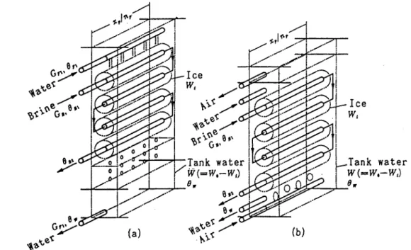
As illustrated in Figure 2, a single-row brine-circuit arrangement is selected for both (a)"a falling film system and (b) a submerged coil system,
Gf*
}z&
^1
&
-Ice ..!*'\p
-K.&sp-^G>
Tank »ator S HiiirI ll/ _l«\ it \=rr,-rrt) J-%* .* å v> e«*A
\* t<3yj&
Ice Tank water W(~W.-W,) 6*and the followings are also assumed to formulate reasonable models: 1. Physical properties such as A,P, cB, cw, L, p, X are constants. 2. Heat loss or gain through tank walls and others is negligible.
3. The supercooling of water does not occur.
4. Ice grows or melts concentrically around the tube, and the temperature profiles across the ice layer satisfy 6=6oln(R/r)/ln(R/ro).
5. Sensible heat capacities of the tube and the ice layer are negligible. 6. The water tank is sufficiently agitated and hence the water temperature
is uniform under the water surface.
7. In the falling film system, the brine circuit is, in the overall sence parallel to the water film flow.
Equations for the falling film system
On the above assumptions, equations for the falling film system are written as follows:
(a) for heat transfer at the position where ice has not been formed
1 1 r. 1 / /~ 1 ^
-=--+
x txnyx o/ x ll x t (1) u h rohFcdGb-t^-JL=
2tcr,Uo(fl»-6.)=-c,Gp-f-^
(2)
eo=e,-^(fl,-9,)
rohF(3)
(b) for heat transfer at the position where ice has been formed
_L_J jrtin(r,/ri) rtln(R/r ) ,» U hb ^p & c,GB4^i=-2itr1U8B (5) d x C w 9^r6r=-2icRhrdr (6) 3 x W TT-PL=-2u(nU0B+Rhr0P)=-L-|-^J: (7) 3 t 3x
and (c) for the changes in the quantity and temperature of tank water and in ice inventory
dW. dWi fXp dR2,
ir=-^r=-
pos *7i-dx=Gp2~Gri
(8)
Qll=CBGb(0B2-0Bl) (9)
cw ^7^-?=-QB+L4T-L=cw(Gp20r2-GP10F1) (10)
dt dt
6F1=0w+Qa/cwGpt (ll)
In the dischargingmode where QB=0 and GB=0, Eqs.(1), (3) to (5),
and (9) are useless; Eqs. (2) are expressed simply as d 6?/dx=0; and
6B=0 in Eqs.(7).
Equations for the submerged coil system
(66 ) T.Fujita
InEqs.(1) to (3) and (6) to (8), erase the terras including Gf, Gfi or
Gp2. and replace hf and 6F with h« and 6w, respectively. Instead of
Eqs.(10) and (ll), use the following Eq.(12):
d
we*
r \ dW C w å =-UBt Wat l-dt dt (12) NUMERICAL ANALYSES Method of calculationApproximate solutions of the above two systems of simultaneous equations are obtained by replacing the derivatives with finite differences. The inde-pendent variables are the distance from the upper end of the coil, x and the time,t. In this paper, each step of the coil is devided into 10 seg-ments at regular intervals, and the time intervals of 30 seconds are adopted for performing calculations under the condition of a pseudo-steady state.
The values of hB are given by Sellars et al./Ref.1/. The values of hr are estimated from Mizushina et al./Ref.2/, which are given by the equation in Table 1. In addition, the values of hw have been estimated to be 0.35 to 0.47 kW/(m2-K) by Fukunaga et al./Ref.3/.
Results on the charging and the dischaging modes
Figures 3 and 4 show examples of the results, calculated under the conditions listed in Table 1. The curves in the figures show the variations in ice inventory, Wi, inlet brine temperature, 6bi and tank water
temperature, 9», The outlet brine temperature, 0B2 has been assumed to be always 2.5T3 higher than 6bi, though it is not shown in the figures.
Figures 5 and 6 correspond to Figures 3 and 4, respectively, showing the
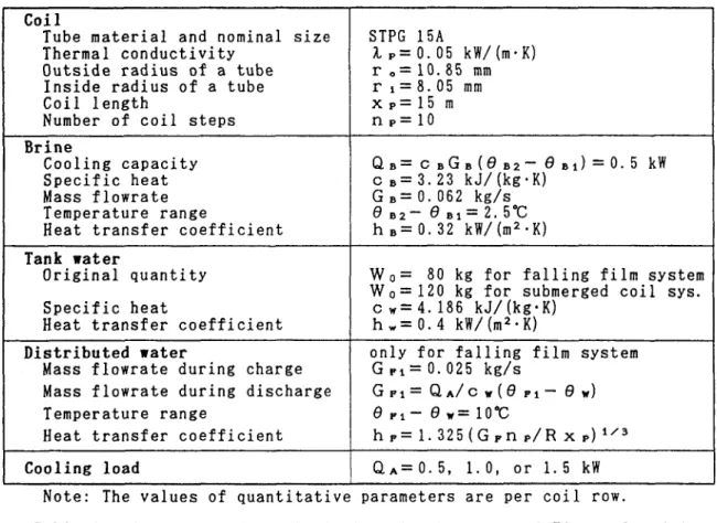
C o i l T u b e m a t e r i a l a n d n o m i n a l s i z e S T P G 1 5 A T h e r m a l c o n d u c t i v i t y I p = 0 . 0 5 k W / (m - K ) O u t s i d e r a d i u s o f a t u b e r o = 1 0 . 8 5 m m I n s i d e r a d i u s o f a t u b e r i = 8 . 0 5 m m C o i l l e n g t h x p = 1 5 m N u m b e r o f c o i l s t e p s n p = 1 0 B r i n e C o o l i n g c a p a c i t y Q b = c b G b ( O b 2 - O b i ) = 0 . 5 k W S p e c i f i c h e a t c b = 3 . 2 3 k J / (k g -K ) M a s s f l o w r a t e G B = 0 . 0 6 2 k g / s T e m p e r a t u r e r a n g e e B 2 - e b i = 2 . 5 -c H e a t t r a n s f e r c o e f f i c i e n t h B = 0 . 3 2 k W / (m 2 -K ) T a n k w a t e r O r i g i n a l q u a n t i t y S p e c i f i c h e a t W o = 8 0 k g f o r f a l l i n g f i l m s y s t e m W o = 1 2 0 k g f o r s u b m e r g e d c o i l s y s . c w = 4 . 1 8 6 k J / (k g -K ) H e a t t r a n s f e r c o e f f i c i e n t h w = 0 . 4 k W / (m 2 -K ) D i s t r i b u t e d w a t e r o n l y f o r f a l l i n g f i l m s y s t e m M a s s f l o w r a t e d u r i n g c h a r g e G r i = 0 . 0 2 5 k g / s M a s s f l o w r a t e d u r i n g d i s c h a r g e G p i = Q a / c サ ( 9 r i - 9 y ) T e m p e r a t u r e r a n g e e p l - 9 w = i o ic H e a t t r a n s f e r c o e f f i c i e n t h p = 1 . 3 2 5 ( G F n P / R x p ) 1 / 3 C o o l i n g l o a d Q a = 0 . 5 , 1 . 0 , o r 1 . 5 k W
Note: The values of quantitative parameters are per coil row.
variations in the apparent outside radius of the ice layer, R. The solid and the dotted lines show the variations in the charging and the discharging nodes, respectively.
In the charging mode, the tank water temperature of the falling film system lowers faster than that of the submerged coil system because of the smaller quantity of tank water, which is followed by the earlier initiation of ice and then the larger quantity of ice or latent heat storage.
In the discharging mode, there are remarkable differences in character-istics between the two systems. The tank water temperature of the submerged coil system has a tendency to rise with the cooling load, which tendency is quite unfavorable to meet higher cooling loads. On the other hand, that of the falling film system is kept stably at 0°C until just before the ice inventory reaches zero even when the cooling load is considerably high. This is due to the high heat transfer coefficient of the film flow. Moreover, in the case of the submerged coil system, the melting of ice proceeds
-81
- Q.-0.5kWI I I I I I I I I I I I I I I
22- 0 8 10 12 14 16 18
Time [o'clock]
Figure 3. Charging and discharging
of a falling film system
40 30| W 3 « 10.85| 0>
i$y\
1st 2nd 3rd 4th 5th 6th 7th 8th 9th 10th| I I I [ I I I I T 0 3 6 9 12 15Distance from top * [m] Figure 5. Variation in ice radius
with time and position; QA=0.5 kW in Figure 3 14 12 E10 4! Ih 2 <O 0, u 93
a-2
(- -4
-6
-8|[I Q,=0.5kW I I I I I I I I I I I I I I I I I I 60 T3 50 -, 30 >> 20 -PioI
0> u 22 0 2 4 6 8 10 12 14 16 18 Time [o'clock] •EFigure 4. Charging and discharging of a submerged coil system
40, K, 30| 20! t/J 3 110.85| O 1st 2nd 3rd 4th 5th 6th 7th 8th 9th 10th| I [ I I I I I I I .0 3 6 9 12 15
Distance from top * [m]
Figure 6. Variation in ice radius
with time and position;
(68) T.Fujita
simultaneously on every step of the coil, whereas in the falling film system, it proceeds step by step from the upper end of the coil.
Results on the compressor-aided dischaging mode
Figure 7 and 8 show examples of the results on the mode that the refrig-erator operates during discharge. An assumed load profile, QA is shown in the figures. The cooling capacity, Qb is assumed to be constant throughout the operation. The conditions of calculations for the charging mode before 8 o'clock are the same as in Table 1, except that Gpi=0.03 kg. The curve ® in Figure 7 is calculated on the assumption that ice is melted from both outside and inside of its layer, while the curve ® only from the outside.
Figure 9 corresponds to Figure 7, showing the variations in the local temperatures of brine and distributed water, 6b and 8p, respecively, and
~ 910i
4 6 10 12 14 16 18 20 22
Time [o'clock] Figure 7. Compressor-aided
discharging mode of a falling film system
22 0 2 4 6 8 10 12 14 16 18 20 22
Time [o'clock]
Figure 8. Compressor-aided
discharging mode of a submerged coil system
3 6 9 12 15
Distance from top x [m] 9. Variations in ice radius,
brine temperature and water temperature with time and position; in the case of® inFigure 7
the outside radius of the ice layer, R.
Even in this compressor-aided discharging mode of operation, the tank water temperature show much the same tendencies as described above. In the
falling film system, the brine temperature rises rapidly in accordance with the enlargement of the coil surface exposed to warmed return water. Such a tendency is favorable because it somewhat improves the COPs of refrigerators. Evaluation of power and energy consumption
The falling film system needs the assistance of a pump for ice making, as in the case of the ice harvesting system. It is estimated that the power required for the pump is about 1 to 2 % of the refrigerator power input and is smaller than that for the air bubbler. It is expected that the falling film system can save the power and energy for the circulating pump more than the submerged coil system, because it can reduce the water flowrate by the extended temperature range available for the secondary air-conditioning
equipment and it does not need an additional power for agitation. EXPERIMENTS
Some experiments were carried out with a single-row brine-circuit coil of 6 steps. Each step of the coil consisted of a carbon steel straight
tube of 21.7 mm o.d., 15.1 mm i.d. and 600 mm length. The spacing between adjacent steps was 100 mm. A tube with a number of holes in line was used as a water distributor. An aqueous solution of ethylene glycol was circulated between the coil and a brine chiller via a brine tank. An electric heater was installed on the way to the water distributor to put heat loads.
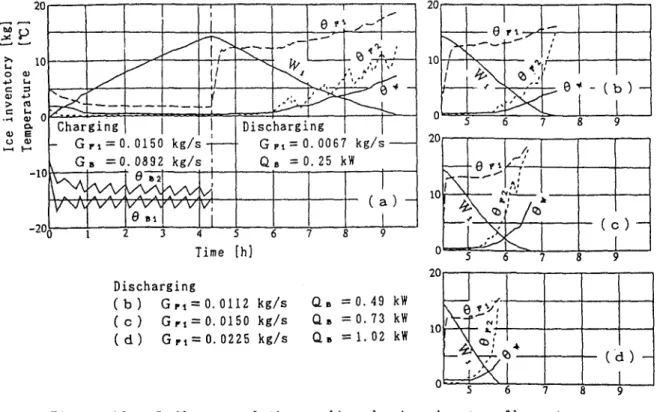
Figure 10 shows an example of the results on the charging and the dischaging modes of operation. As shown in this figure, The falling of ice from the coil did not exert an serious effect on the melting rate.
20, 10 u O <1> C 3 > n i- l a> 0 o. 0) E O 0) *-<I--101 -20,
S3
ChargingJ
- Gn=0.0150 kg/s G» =0.0892 kg/s 6T3KWivi
^7I
w
0Bl v^v Discharging Gpi=0.0067 kg/s QB =0.25 kW "2" 3 4" 5" ~6~" Time [h] Discharging (b) Gn=0.0112kg/s (c) Grt=0.0l50kg/s QB =0.49 kW QB =0.73 kW (d) GP1=0.0225kg/s CU=1.02kWFigure 10. Influence of the cooling load and water flowrate on discharging in the experimental falling film system
(70)
T.Fujita
CONCLUSIONS
Judging from the results of the numerical calculations and the experi-ments, the ice thermal storage system of a falling film type is promising for air-conditioning use. Refer to the SUMMARY.
NOMENCLATURE
c specific heat, kJ/(kg-K) G flowrate per coil row, kg/s
h heat transfer coefficient, kW/(m2*K) L latent heat of fusion of ice,
334 kJ/kg
np number of coil steps
Q.a cooling load shared by a coil, kW QB cooling capacity of a brine coil, kW
t time, s
R outside radius of an ice layer, m r radial coordinate, m
ri inside radius of a tube, m ro outside radius of a tube, m W quantity of water in a tank, kg Wi quantity of ice (ice inventory), kg Wo original quantity of water in a tank,
W0=W+Wi, kg
x axial coordinate, m Xp coil length, m 6 temperature, °C
Qo temperature of the outside surface of a coil, °C X thermal conductivity of ice, 0.00221 kW/(m-K) XP thermal conductivity of tubing, kW/dn-K) p dencityof ice, 917 kg/m3 Subscripts
1 upper end of a coil 2 lower end of a coil B brine
F distributed water W tank water
REFERENCES
/I/J. R. Sellars et al., TransASME (1956), Vol.78, No.2, p.441.
ll/ A. Mizushina et al., Kagaku Kogaku (1967), Vol.31, No.5, pp.469-473.
/3/ K. Fukunaga et al., Proc SHASE National Meeting (1987), pp.653-656.
SUMMARY
Water and ice thermal storage air-conditioning systems are being applied increasingly for load shifting and levelling. Proposed is a new type of ice thermal storage system. It takes advantage of falling thin water films, consisting of a water distributor, brine or refrigerant coils inside an insulated chamber, a water tank under the chamber, and a circulating water pump(s). Ice is formed on the outside of the coils through recirculation of tank water. Ice is melted from the top of the formation in direct contact with return water from the secondary circuit of an air-conditioning system.
The results of theoretical and experimental works have shown that the system has the following features in comparison with currently-used ice-on-coil systems, of which coils are submerged:
1. The needed volume of water decreases and any agitators are unneeded. 2. In the charging mode of operation, the rate of water chilling increases
and hence the rate of ice making also increases.
3. In the discharging mode of operation, supply water temperature can be kept stably near 0°C even at high cooling loads.
4. The coefficient of performance is improved in the compressor-aided discharging mode of operation.