21st International Conference on Composite Materials Xi'an, 20-25th August 2017
TENSILE PROPERTIES OF FRP PLY SPLICE STRUCTURES
Dingding Chen
1, Manyi Wang
1, Yueyao Shen
2and Kazuo Arakawa
31 College of Basic Education, National University of Defense Technology, China.
Keywords: fiber reinforced composites, Ply splice, Tensile property
ABSTRACT
When the FRP structure becomes large, it is required to splice two or more plies to meet the size
requirement. In order to understand the mechanical property of the FRP ply splice structure and get
strong ply splice structures, the tensile properties of three kinds of unidirectional CFRP ply splice
structures have been tested in the previous work in [1]. In this paper, another two structures were
designed based on the S 1 structure in [ 1], in order to improve the strength of this type of the ply splice
structure. Compared with the S 1 structure, the difference of the S 1-1 structure was that the spliced
point of each ply was optimized to extend the distance between the nearest spliced points. In the S 1-2
structure, additional two carbon fiber fabrics were attached on each side of the S 1-1 structure to
restrain the bending of the specimen under a tensile load to improve the tensile strength. The results
show that there is no big difference of the tensile strength between S 1 and S 1-1 structures, however,
S 1-2 really performs much higher tensile strength.
1 INTRODUCTION
Due to high strength and low density, fiber reinforced plastics (FRP) have been used widely, and
FRP structures with large size are required by more and more applications. When the FRP structure
becomes large, only one reinforcement ply may not large enough. In the previous work [1], the tensile
properties of three kinds of unidirectional CFRP ply splice structures were studied. The results show
that, inducing ply splices into CFRP materials, the tensile strength decreases evidently. Due to the ply
splice, stress concentrations occur, and the initial fracture happen�in the ply splice position, leading to
the final fracture on the interfaces between different plies. The interlaminar shear stress and the tensile
stress in the through-thickness direction near the ply splice position are the key factors leading to the
initial failure. In this paper, some improvements were made based on one of the three ply splice
structures, expecting to get higher strength.
2 EXPERIMENTS
Two kinds of CFRP plates with ply splice structures were made through vacuum assisted resin
transfer molding (VaRTM) process. As shown in Figure 1, the black line represents the unidirectional
carbon fiber fabric, TENAX STS from Saeertex GmbH. The matrix was XNR/H6815 epoxy resin
from Nagase. Four fabrics were adopted in each kind of specimens. The thickness of all the specimens
is about 2 mm. The fiber volume content is about 55%.
The S 1 specimen is the structure in [ 1]. S 1-1 was modified from S 1. The splice points on the first
and the fourth ply were changed, in order to extend the distance between the splice points on the first
(or the second) and the third ply (or the fourth). Based on S 1-1, additional two carbon fiber fabrics
were attached on each side of it, getting S 1-2 specimens.
Static tensile tests were performed to evaluate the four joints. The dimensions of the specimens are
shown in Figure 2; the length was 250 mm and the width was 10 mm. Two pairs of tabs made with
glass fibre-reinforced plastic (GFRP) were used for each specimen to reduce stress concentrations. The
length of the tab was 50 mm. The crosshead speed was 1 mm/min. The tensile stress was along the
Initial status 80. ls
21st International Conference on Composite Materials Xi'an, 20-25th August 2017
97.7s 98.6s
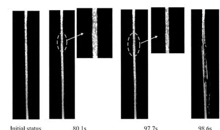
Figure 5. Fracture evolution of S 1-1 structure
Initial status l 02:0s I 02.9s Figure 6. Fracture evolution of Sl-2 structure
Compared with the S 1 structure, the difference of S 1-1 structure is that the spliced point of each ply is optimized to extend the distance between the nearest spliced points. This modification may have obvious positive effect on reducing the fiber direction tensile stress component of the stress concentration in the vicinity of the spliced point, however, have almost no effect on the other components. The previous work has shown that the tensile stress along the fiber direction is not the key factor deciding the final strength, coinciding with the strength of the Sl-1 structure. In the Sl-2 structure, additional two carbon fiber fabrics were attached on each side of S 1-1 structure to restrain the bending of the specimen under a tensile load to improve the tensile strength. The results show that this modification really can make the structure stronger.
4 CONCLUSIONS
In this paper, two structures were designed based on the Sl structure in [1] in order to improve the strength of this type of the ply splice structure. Compared with the S 1 structure, the difference of S 1-1 structure was that the spliced point of each ply was optimized to extend the distance between the nearest spliced points. In S 1-2 structure, additional two carbon fiber fabrics were attached on each side of S 1-1 structure to restrain the bending of the specimen under a tensile load to improve the tensile strength. The results show that there is no big difference of the tensile strength between S 1 and S 1-1 structures, however, S 1-2 really performs much higher tensile strength, coinciding with the analysis and conclusions in [1].
First A. Author, Second B. Author and Third C. Author
ACKNOWLEDGEMENTS
This work was supported by the Natural Science Foundation of China (NSFC) [grant numbers
51503223] and the Collaborative Research Program of the Research Institute for Applied Mechanics,
Kyushu University.
REFERENCES
[1]
D. Chen, M. Wang, K. Arakawa, S. Jiang, K. Wu and Q. Hu, Tensile properties of FRP ply
splice structures, Acta Materiae Compositae Sinica, pp. 1-6.
Bending strength of CFRP laminated adhesive joints
fabricated by vacuum-assisted resin transfer molding
MahmoudR. Abusrea
a,b, Seung-Wook Hane, Kazuo Arakawa叫 Nak-Sam Choic* a Faculty of Engineering, Cairo University, Giza 12613, Egyptb Interdisciplinary Graduate School of Engineering Sciences, Kyushu University, Fukuoka 816-8580, Japan c Department of Mechanical Engineering, Hanyang University, Ansan 426-791, South Korea
d Research Institute for Applied Mechanics, Kyushu University, Fukuoka 816-8580, Japan
Abstract
The laminated joints in this work were an adhesive joint constructed using two dry carbon fiber halves. For the joints, some improvements were introduced to enhance the bending strength performance: Stitching of the two halves together by fiber bundles, and inserting extra carbon fiber covers in the joint connection. We studied three adhesive joints: conventional basic laminated joint and the two improved laminated joints. All joint specimens were fabricated in our laboratory using vacuum-assisted resin transfer molding (V ARTM) process. The joint performance was evaluated with a bending test, and was compared to the bending strength of jointless carbon fiber reinforced plastic (CFRP) laminate. Two acoustic emission (AE) sensors were placed on a specimen to monitor the fracture progresses during the test. The improved laminated joints, stitched joint and multiple-covers-overlapped joint, showed enhanced bending strength and joint efficiency as well. The improvement depended significantly on the number of carbon fiber layers. The maximum increase in comparison to the jointless CFRP was 24% for stitched laminated joint of 5 layer laminates and 58% for multiple-overlapped joint of 6 layer laminates, respectively. Such high joint efficiency was due to carbon fiber reinforcement effects in the joints that many carbon fibers supported the strength in advance ofreaching the maximum load point as indicated by AE detection analysis.
Keywords- CFRP joints, vacuum-assisted resin transfer molding, bending strength, joint efficiency
1. Introduction
The use of carbon fiber remforced plastic (CFRP) composites in engineering structures has many advantages because of their high mechanical performances such as high strength-to-weight and stiffness-to-weight ratios [ 1]. For this reason, they have applied to heavy duty structures in aviation, space [2, 4], automotive [3], shipbuilding [4], and wind turbine [5]. These applications generally involve large-scale manufacturing, and the parts are made from smaller components and are joined together. In this case the mechanical performance of such CFRP structures is highly dependent on the properties of the joint parts.
Since composite joints work as crucial load-carrying elements their design and analysis is a key process in the large scale applications to accomplish light weight, low-cost and efficient composite structure integration [6]. There are conventional mechanical fasteners such as bolts, pins, and rivets to join CFRP structures [7]. These mechanical joints are often prefe汀ed due to the conveniences that such fastening joints can be disassembled for repair and/or recycling [8]. However, drilling holes made for parts joining may induce localized damage in the composite due to stress concentration when the joint is loaded. In contrast, adhesively bonded joints may have mechanical advantages better than bolted joints because the reinforcing fibers are not cut, and thus the stresses are transmitted more homogeneously [9]. Besides, bonded joints can provide good structural integrity, low weight and high strength-to-weight ratios [ 10-12]. Nowadays adhesive composite joints are applied widely in many composite structures for aerospace, turbine, and ship designs [13]. These engineering struc血res are subjected to combinations of static, fatigue and impact loadings. Not only conventional single-lap [9], double-lap [14] and stepped [15] adhesive joints, but also improved adhesive joints have been studied to improve the mechanical performance of adhesive composite joints. For instance, Lobel et al. [ 16] enhanced tensile strength by introducing z-pinning into CFRP double-lap joints. Another approach for adhesive joint improvement was reported by Mouritz et al. [17] who placed spiked metal sheets in the bond-line to facilitate mechanical load transfer. Furthermore, stitching was a technique for reinforcing the laminated joint. Dransfield et al. [ 18] and HeB et al. [ 19] clarified that the stitching enhanced the fracture toughness of laminated composites under peel loading. Kim et al. [20] made some stepped-lap joints as a function of the number of steps, joint length, and edge angle of the adherends, and showed a considerable improvement in the fatigue performance by increasing the number of steps
Table 1. Detailed information of the carbon fabric [30]
Tensile Tensile
Weight Density Thickness Elongation
Carbon fiber No of strength modulus
Style designation filaments g/m2 g/cm3 mm MPa GPa % TRK976PQ UD 12,000 317 1.82 0.33 4,900 253 1.9 RW IM
The laminated joints proposed in this work are a composite adhesive joint constructed of two mating dry carbon halves which were stacked in a pre-determined order prior to the VARTM process [10-12] schematically shown in Fig.I. Three joint types were adopted in this work. The adhesive joint constructed of only two mating dry carbon halves
was a basic original type (see BLJ of Fig. 2a). The joint length was 40 mm in the total specimen length of 80 mm. The fiber volume fraction measured for the joints was approximately 62%. One improvement to this joint was made by applying a stitching technique. Fig. 2b shows a stitched laminate joint (SLJ). We conducted stitching with carbon bundles of the same carbon fiber type, which were applied perpendicular to the plane of the laminate [ 18-19]. Abusrea and Arakawa [ 11] showed a weakened stepped joint in which stitching was applied; the tensile strength of the stitched stepped joint was 26% lower. However, it showed improved tensile strength when the stitching was applied to the dry carbon-to-dry carbon joint state. The other improvement was made by adding carbon fiber covers of 40 mm in length which had been prepared beforehand by sectioning the carbon fiber layers. Each carbon fiber cover was put on the contact region between the end parts of two mating d
_ry carbon fiber layers. After finishing the V ARTM process [10,11] the inserted carbon fiber covers may reinforce the mterphase layer between the two overlapping carbon halves, and may alleviate stress concentration at the fiber ends of carbon halves. This joint type is named as a multiple-covers overlapped laminate joint (MCLJ) (see Fig. 2c). We applied four different numbers of carbon fiber layers for all joints. We chose 5, 6, 7 and 10 carbon fiber layers as these numbers were common in industry use. On the other hand for the basic type of a laminated joint, two different cases were made: a normal .BLJ and a'shifted'basic laminated joint (S BLJ). For the normal BLJ, the six and ten carbon fiber layers were stacked'co汀ectly'at their right positions; that is, there was no gap between the fiber ends (Fig. 2a). For S-BLJ, the five and seven carbon fiber layers were a bit shifted to form a gap between the fiber ends (Fig. 2b). Because a shifted placement of carbon fiber layer may be conducted during mold preparation for this kind of adhesive joint fabrication, the S-BLJ was used to examine the effects of such shifting on the final product quality in terms of thickness variation, and on the mechanical performance in terms of bending strength.
�
Before molding
1
匹匹
I
(a)
After molding
□
三
王号
→
If
,--4士0.5 mm;c�
Before molding
(b)
Local thinning
Figure 3. Schematic drawing before and after molding for the (a) normal basic laminated joint (BLJ) and (b) shifted laminated joint (S-BLJ).
2.2. Mechanical testing with AE measurement
The nominal bending strength was measured [24] to evaluate the joints'mechanical performances. The cured CFRP joints were sectioned to form specimens for the three-point bending tests, with the geometry shown in Fig. 4. Five specimens were prepared for each test condition. The span (L) and the width (W) of the test specimens were 50mm and 12.7mm, respectively. The thickness (t) of the joints was varied according to the joint types of Fig. I, and thus measured for the individual joint type in advance of the tests. The thickness (to) of the unjointed part of the test specimens was also measured. During the test, each specimen was monitored with AE measurement. The bending test was carried out at room temperature with a universal testing machine (Zwick 250, Test Xpert, version 11) with a crosshead rate of 3 mm/min. Fracture processes were examined in real time using two AE sensors (micro30, Physical Acoustic Corp.), marked as S 1 and S2, which were attached to the bending specimen using vacuum grease and mechanical fixture. The two AE sensors were put 46 mm apart, each one is 23mm distant from the specimen center. They were placed in such positions close to the joint ends. A two-channel AE detection system (MSTRAS 2001, Physical Acoustic Corp.) was used to record the AE data, and the AE measurement conditions were a pre-amp of 40dB, a threshold level of 40 dB, and a sampling rate of 4 MHz. The threshold was positioned at a comparatively high level so as to filter the noisy sounds coming from other emission sources. A band-pass filter under software control (pass range frorp 1 kHz to 1 MHz) was used for signal gain at specific frequencies. Three AE parameters were investigated: amplitude, energy, and frequency spectrum of AE signals. AE analysis may provide a way to identify and differentiate fracture sources [24,25]. Consistent with Yoon et al. [24], we ascertained that the distance between the sensor and the crack location was close enough to measure the AE characteristics. Considering the attenuation problems at high frequencies, we focused primarily on frequency bands below 400 kHz for verification of the fracture mechanisms. Fractographic analysis was also performed on damaged specimen surface and/or the fracture surface through observation by optical and scanning electron microscopy (SEM).
80 L. N
tM
ご
一
ー
p
― .
に
し
*All d1mens1ons 1n mmFigure 14. Illustration of an adhesive joint specimen under the three-point bending test with acoustic emission (AE) monitoring.
2.3. Data reduction of the adhesive joints under the bending test
The maximum load taken during the bending test of Fig.4 is used to evaluate the mechanical performance of the composite adhesive joints. It is reasonable that the joint performance should be compared with the bending strength of jointless original composite laminates. In this respect, the'nominal'bending strength cr1 for every joint type can be calculated using
CJJ = 3PL/2Wt訊, (1)
where P is the maximum load value obtained from the load-deflection curve of the respective joint types , L the span length, W the specimen width, and to the thickness of the unjointed ligament part. The nominal bending strength assumes that the adhesive joint has a thickness equal to the unjointed ligament part. However, the thicknesses of the composite adhesive joints are varied according to the adhesive joint types, and can bring about a large variety of actual bending strength. Thus a joint efficiency (TJ) for the various joint types is evaluated with reference to the bending strength (era) of the jointless original composite laminate and can be determined by a simple equation
1} = (Jj/0:
。
(2)For S-BLJ, the nominal bending stress (cr2) on the surface at the thinned section of a joint specimen is given by
び2 = 3Pb/Wtc2, (3)
where b is the distance between the support roller and the thinned section, and tc the thickness of the thinned part.
3. Results and discussion
3.1. Thickness profile behaviors of the joint specimens
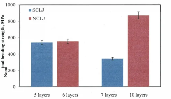
Table 2 shows thickness measurement data obtained for the normal BLJ. The average thicknesses were 1.83 and 3.04 mm for 6 and 10 layers, respectively. The minimum thickness and the maximum deviation were also measured for evaluating the product quality. The thickness deviation ranged to 2.8% for 6 layers and to 3.5% for 10 layers. For the S-BLJ, the average thicknesses for 5 and 7 and layers were 1.46 and 2.02 mm, respectively as shown in Table 3. The thickness deviation was as high as 23 %. The low minimum thickness and the large deviation indicate a bad quality that may lead to a weaker strength for the thinned part of the S-BLJ specimens. Several previous papers mentioned that the thickness variation was one of the geometrical parameters that exerted a bad influence on the performance of the adhesively bonded joints [41]. For example, a local thinning due to the thickness variation could affect the stress concentration, the strain inhomogeneity as well as the crack initiation. Ribeiro et al. [42] calculated the stress distributions along single lap adhesive joint to show a rapid increase in stress gradients around the overlap edges. Jensen et al. [ 43] showed a strain inhomogeneity reaching nearly 20% of the mean strain value in composite laminates under a transverse load.
Figure 5 compares the specimen thickness profiles along the specimen lengthwise direction for the three kind of joints ( normal BLJ, stitched BLJ and MCLJ) with the same 6 fabric layers, and also for an'ideal'6-layer jointless CFRP. The stitched joints showed higher thickness deviation especially at the stitched sites. The thickness deviation was about士0.45 mm. Much greater thickness increase at the joint part was observed for the MCLJ. The thickness at the joint part along the joint length of 40 mm was measured to be 3 .3 mm on average, which was almost twice the thickness of the jointless CFRP. This was because the number of carbon fiber covers made additional thickness exceeding the initial thickness of the adherend constructed of the original number of carbon fiber layers. This big variation in the thickness appeared along the upper surface profile of the joint part because all carbon fiber layers including the additional covers were placed on a rigid flat surface of the mold as illustrated in Figure 1 c.
1000
■
SCLJ
�� 800
■
NCLJ
i
ぢビ 600
i
且
=
400
頁
』
200
゜
5 layers
6 layers
7 layers
10 layers
Figure 6. Bending strength results for normal basic laminated joint (BLJ) and shifted BLJ specimens
Such bending strength behaviors may be clarified on the basis of AE analysis in combination with microscopic fractography. Figure 7 shows a typical bending stress curve versus time for normal BLJ specimen of 6 layers which was recorded together with accompanying AE amplitudes. With increasing displacement the load began to increase and then dropped down largely just after reaching the peak, and finally decreased very slowly. Low amplitude emission occurred from the low level of load, whereas big amplitude emission began to be generated around 65% of the peak load, and then appeared intermittently until the peak load. High amplitudes may correspond to fiber breakages while low amplitudes may arise from crackings in the resin and/or interface between fiber and matrix, as ascertained in ref. [ 24,25]. In this sense it was confirmed that for normal BLJ some amount of reinforcing fibers were broken before reaching the bending strength. However only low amplitudes arose with the rapid load drop just after the peak. After finishing the large load drop, very high amplitudes were generated again, following a mild AE behavior.
Typical bending stress behavior for 5 layers S-BLJ specimens with accompanying AE amplitudes is shown in Fig.8. Clear differences from the normal BLJ appeared in this figure. The peak load level for S-BLJ was a bit lower, and the load drop proceeded in several steps and times. �ig amplitude emissions began to occur at quite high level of 90% peak load prior to the peak, and sustained for a considerably long time with a slow decrease of load after the peak load. This behavior shows that around the peak load the reinforcing fibers were broken in a very different process from the normal BLJ. After passing such strong emission period, the load dropped down to around 50% of the peak load
1400 1200 尽Iwoooooog# s�u!puaa 1000 800 600 400 200
゜ ゜
―Bending stress―
Amplitude 100 90 80 70 60 HP 'apn:mdmy 50 40 20 40 60 Time, s 80 100Figure 7. Typical bending stress curve versus time with accompanying AE amplitudes for normal BLJ specimen constructed of 6 fiber layers.
1200 1000 SIKぶSa.lJS�ll!PUa9 800 600 400 200
―
Bending stress ―Amplitude 100 90 gp 'apnindmv 0 0 0 8 7 6 50゜ ゜
20 40 60 80 Time, s 100 120 140 160 40Figure 8. Typical bending stress-time curve with accompanying AE amplitude for a S-BLJ specimen of 5 fiber layers.
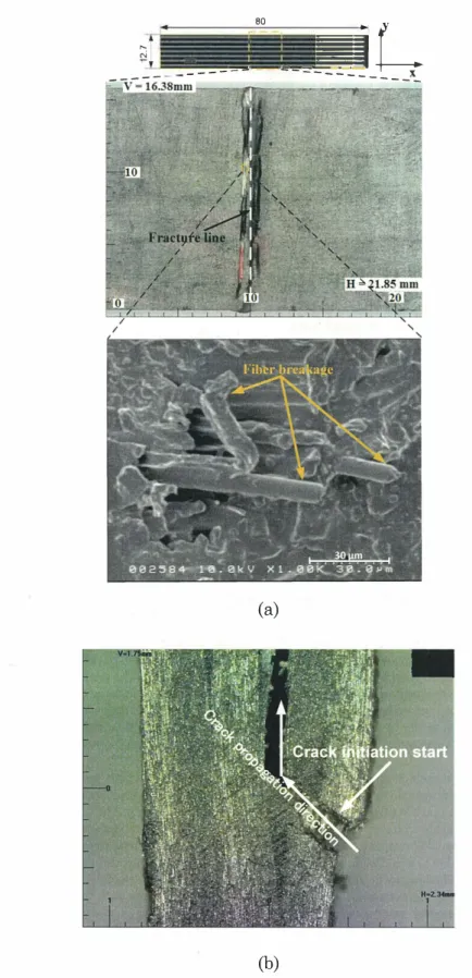
Fractographs taken for the normal BLJ and S-BLJ were analyzed as shown in Figure 9. For the normal BLJ
specimen, a tensile bending fracture occurred along the center line of the specimen 20mm distant from the joint ends, and it induced many fiber breakages as revealed in SEM observation (see Fig.9a). It is to be noted that the tensile bending stress at the joint end of this specimen calculated by equation (3) approached only about 80% of the peak stress at the middle of the specimen. Shorter the distance of the joint end from the specimen center, larger the tensile stress arising at the joint end should be. Thus short joints can cause a fracture at the joint end because the joint ends have a weaker strength by lack ofreinforcing fibers, which may lead to a lower joint strength than the long joints used in this study. In contrast, the S-BLJ showed a different failure behavior as confirmed by optical microscopic observation
(see Fig. 9b). A resin crack initiated at the joint end where the local thinning had been formed as exhibited in Table 3, and proceeded in the loading period without observed fiber breakages along the laminate interface. This phenomenon was also confirmed in accordance with the low amplitude distribution until about 90% the peak load as shown in Fig.8. The S-BLJ can arouse a peak tensile stress at the bottom of the concaved part where the local thinned section was located. For this stress analysis, a stress concentration effect should be considered on the basis of the measured notch length a and the measured notch tip radius Pt by the equation:
Stress concentration factor (Kt) = ;:9::i::l s;;;;;
s (���= [ 1 + 2
*長]
(4)The values ofK1 for S-BLJ specimens of 5 and 7 layers may be estimated as 1.34 and 1.45, respectively. The high stress values beyond the stress at the center of the joint specimen must have caused such crack initiation at the local thinned position leading to a low bending strength of S-BLJ specimens. However many fiber breakages seemed to occur just around the peak load in the process .of macroscopic delamination in the joint part, as indicated by the strong amplitude emissions shown in Fig.8. It is thought that the collapse mechanism of S-BLJ specimens was significantly associated with not only the resin cracking and delamination in the loading stage but also the fractures of reinforcing fibers in the joint.
Fracture mode detection using AE frequency analysis was performed in the entire loading stage. We classified the AE features according to the fracture mode on the basis of the previous study results in which low spectral features below 160 kHz corresponded to the resin fractures, intermediate spectral features in the range of 160-240 kHz corresponded to the matrix-fiber mixed fractures, while high spectral features above 240 kHz were associated with the fiber fractures [24,25].
Figures 10 shows percentage data of AE energy accumulated until just after the peak load point according to the above mentioned frequency bands for all specimens. Different fracture behaviors were identified for the normal BLJ and S BLJ. It was found that for the normal BLJ the AE energy spectra occurred very mostly (85 ~ 90%) in the high frequency band (f > 240 kHz). Thus, the dominant fracture mode was obviously the fiber breakages. On the other hand, the S-BLJ showed that the resin crackings were in a considerable majority in the overall loading stage, because a high fraction (50 ~ 65%) of the AE energy spectrum occurred in the low frequency band (f <160 kHz). A significant portion (20~30%) of the fiber breakages was also shown in this joint, which should have arisen through the delamination process in the joint part as confirmed with the strong emissions in Fig.8.
L. N
.
一
国目
----
= 80 •: y―
-
-
�
―
�-'
-
-
ー
_
—
-
三
(a)
(b)
Figure 9. Typical optical microscopy and SEM micro graphs for the fracture of (a) normal BLJ with 6 layers and (b) S-BLJ with 5 layers
3.4. Bending strength and fracture processes of multiple-covers laminated joints
MCLJ achieved much higher nominal bending strength than the basic laminated joint. As shown in Fig.13 the MCLJ with 6 layers had a bending strength of2.33 GPa, which represented the maximum bending performance among all the tested MCLJ types. The strength value indicated a drastic increase by 321 % than the normal BLJ and a considerable increase by 66% than the stitched BLJ. The other MCLJ with 10 layers showed a decreasing value of 1.29 MPa, still larger than the stitched BLJ. The increase in the bending strength for the MCLJ can be explained by simple stress analysis: The insertion of seven extra carbon fiber covers as illustrated in Fig.2c made a thick laminated joint which could work as a multiple-bonded double lap joint (DLJ). Because the MCLJ specimen was manufactured with the VAR TM method, the joint part smoothly changed to the thin ligament adherend by filling the resin to the comer between the thick joint part and the thin adherend. The thickness of the joint part was almost twice as large as that of the adherend. In this case the tensile stress at the bottom surface of the joint part is calculated to be one-fourth of that for the corresponding BLJ according to equation (1) under the same bending load. The macroscopic fracture shown in Fig.14 proceeded at the center line of the joint part, which was similarly observed also for the normal BLJ specimen (Fig.9). When the same material strength is assumed for both the BLJ and MCLJ, bending strength ofMCLJ should be four times as large as that for BLJ, which agreed well with the above bending strength result about 4.21 times larger than the BLJ. The small mismatch of the bending strength data between measurement and calculation might be considered due to the fluctuated deviation in the thickness of the joint part (see Fig.5).On the other hand, the thickness change from the adherend to the joint part was measured as shown in Fig.5, which should induce a peak stress concentrated at the local site just where the joint began from the adherend. However all the fracture events only occurred in the middle of the joint part, which indicates that the peak stress at the boundary site of the joint part did not reach the tensile strength of the MCLJ specimens. The peak stress site and the fracture initiation might occur probably at the end of the joint part with decreasing the length ofMCLJ part in comparison to the test span. In this case the bending strength mechanisms should be different on account of the fracture process arising at the joint ends.
The macroscopic fracture along the center line of the joint part was similar for all the MCLJ specimens with various layers adopted in this study. The MCLJs with 5, 7 and 10 layers showed lower bending strengths than the MCLJ with 6 layers. The low bending strength for the 5 layers joint might be predicted with the simple stress theory of equation (1) stated above for the 6 layers joint, in that the 5 layers joint had an average thickness larger by about 10% than that expected from the normal layup thickness. The rather thicker 5 layers joint was due to the more resin infiltration in the V ARTM process than the 6 layers joint. However the decreasing bending strength of MCLJs with 7 and 10 layers could not be clarified with the simple stress theory, but be attributed to a large defect formation in the thick layup joints. For the 7 and 10 layers joint, extra fiber covers were inserted between the layers causing much thicker joint part which could contain bigger voids during the VAR TM process. The existence of critical large voids might induce an easy fracture of the thick MCLJ. Figure 15 shows typical percentages of AE energy in the three frequency bands for MCLJs with 5, 6, 7 and 10 layers. Most MCLJ specimens emitted a high percentage (60~ 98%) of AE energy in the high frequency band (>240 kHz). This represents that fiber breakages were very dominant in the fracture process until the peak load as confirmed again in the SEM observation of Fig.I 4. The bending strength behaviors of Fig.13 which largely depended on the thicknesses of MCLJs are considered to have been associated mainly with a fracture procedure of the carbon fabric during the loading stage.
Joint efficiencies for all the types of laminated adhesive joints were calculated using equation (2) in comparison to the jointless CFRP laminates as summarized in Fig.16. The average bending strength of the jointless CFRP was measured to be around !1500 MPc1;[Cl]. For normal BLJ, joints efficiencies were distributed in the range of 24% ~ 58%. For stitched LJ, the joint efficiency was the largest (124%) at the 5 layers joint, however the increasing layers over 5 layers reduced significantly. Excellent joint efficiency exceeding 100% was also shown for the MCLJs with 5 ~ 7 layers. The best efficiency among all the joint types was obtained at the 6 layers MCLJ.
4. Conclusions
The laminated adhesive joints were made using VARTM process. Three types of laminated joints were studied: conventional basic laminated joint (BLJ), stitched laminated joint (S�J), and multiple-covers overlapped laminated joint (MCLJ). All joint specimens were tested under the three-pomts bending load to evaluate their strength performances in terms of the nominal bending strength. For normal BLJ, increasing layers improved the bending strength while a shifted layup formed a concave notch where larger number of layers caused weaker bending strength. Acoustic emission analysis and fractographic observation confirmed that the fracture mode for the normal BLJ was mainly fiber breakages prior to the maximum load point which dominated the bending strength mechanisms of normal BLJ. The shifted layup in the joint caused the fracture initiation mode to be the resin cracking at the notch site. On the other hand, stitched laminated joints (SLJs) showed much improved bending strength compared to the BLJ. The SLJ with 5 layers showed excellent joint efficiency around 124%. The MCLJ achieved superior bending strength in which the joint efficiency for 5 ~ 7 layers joints exceeded 120%. The best efficiency among all the joint types was obtained at the 6 layers MCLJ. It was confirmed by combined AE and microscopic analysis that fiber breakages were very dominant, i.e. fiber reinforcement caused the superior bending strength for the two joint types of SLJ and MCLJ. Consequently, stitching and multiple covers insertion reinforced clearly the adhesive joints, in which some optimal layup thickness and surface profile perfectness formed by the VAR TM were required to show the be·st bending strength.
ACKNOWLEDGMENT
This work was partly supported by a research grant from the Japan Society for Promotion of Science (#JP26630496), and by the Collaborative Research Program of Research Institute for Applied Mechanics, Kyushu University.
References
[1]. T. Keller, T. Vallee. Adhesively bonded lap joints from pultruded GFRP profiles. Part I: stress-strain analysis and failure modes. Composites: Part B 36 (2005), pp. 331-340
[2]. L. B_ums, AP. Mouritz, D. Pook , S. Feih . Strengthening of composite T-joints using novel ply design approaches.
Composites: Part B 88 (2016), pp. 73-84.
[3]. Shufeng L , Xiaoquan C , Qian Z, Jie Z, Jianwen B, and Xin G. An investigation of hygrothermal effects on adhesive materials and double lap shear joints of CFRP composite laminates. Composites: Part B 91 (2016), pp. 431--440
[4]. Akderya, T., Kemiklioglu, U., & Sayman, 0. (2016). Effects of thermal ageing and impact loading on tensile properties of adhesively bonded fibre/epoxy composite joints. Composites Part B: Engineering, 95, 117-122 https://doi.org/10.1016/j.compositesb.2016.03.073
[5]. Abusrea, M. R., & Arakawa, K. (2016). Improvement of an adhesive joint constructed from carbon fiber reinforced plastic and dry carbon fiber laminates. Composites Part B: Engineering, 97, 368-373 doi: 10.1016/j.compositesb.2016.05.005
[6]. Xiang, J., Zhao, S., Li, D., & Wu, Y. (2017). An improved spring method for calculating the load distribution in multi-bolt composite Jomts. C ompos1tes Part B: Engmeermg, 117, 1-8.
https://doi.org/10.1016/j.compositesb.2017.02.024
[7]. Friedrich, C., & Hubbertz, H. (2014). Friction behavior and preload relaxation of fastening systems with composite structures. Composite Structures, 110, 335-341. doi: 10.1016/j.compstruct.2013.11.024
[8]. Lee, Y.-H., Lim, D.-W., Choi, J.-H., Kweon, J.-H., & Yoon, M.-K. (2010). Failure load evaluation and prediction
of hybrid composite double lap joints. Composite Structures, 92(12), 2916-2926. doi: 10.1016/j.compstruct.2010.05.002
[9]. Oplinger JW. Mechanical fastening and adhesive bonding. In: Peters ST, editor. Handbook of composites. New York: Springer; 1998
[10]. Abusrea, M., R., Jiang, S., Chen, D., Arakawa, K., . Novel CFRP Adhesive Joints and Structures for Offshore Application. International Journal of Chemical, Molecular, Nuclear, Materials and Metallurgical Engineering 9 (9),2015
[11]. Abusrea, M., R., and Arakawa, K., Evaluation of the strength of CFRP adhesive joints manufactured using VAR TM. Advanced Experimental Mechanics, Vol.I (2016) 111-114.
[12]. Chen, D., Arakawa, K., Jiang, S., . Novel joints developed from partially un-moulded carbon-fibre-reinforced laminates. Journal of Composite Materials, 2015, Vol. 49(14) 1777-1786.
[13]. Ascione, F. (2016). The influence of adhesion defects on the collapse ofFRP adhesive joints. Composites Part B: Engineering, 87, 291ー298. doi:10.1016/j.compositesb.2015.10.033
[14]. Heim, D., Hartmann, M., Neumayer, J., Klotz, C., Ahmet-Tsaous, 6., Zaremba, S., & Drechsler, K. (2013). Novel method for determination of critical fiber length in short fiber carbon/carbon composites by double lap joint. Composites Part B: Engineering, 54, 365-370. doi:10.1016/j.compositesb.2013.05.026
[15] Salih A沖inar. The strength of the adhesively bonded step-lap joints for different step numbers. Composites: Part B 67 (2014) 170-178 doi:10.1016/j.compositesb.2014.06.023
[16] Lobel, T., Kolesnikov, B., Scheffler, S., Stahl, a., & Htihne, C. (2013). Enhanced tensile strength of composite joints by using staple-like pins: Working principles and experimental validation. Composite Structures, 106, 453-460.
doi: 10.1016/j.compstruct.2013 .06.020
[17] Mouritz AP, Chang P, Cox BN. Fatigue properties of z-pinned aircraft composite materials. ICAS Int Cong Aeronaut Sci 2006.
[18] Dransfield, K. A., Jain, L. K., & Mai, Y.-W. (1998). On the effects of stitching in CFRPs—I. mode I delamination toughness. Composites Science and Technology, 58(6), 815-827. doi:10.1016/S0266-3538(97)00229-7
[19] HeB, H., & Himmel, N. (2011). Structurally stitched NCF CFRP laminates. Part 1: Experimental characterization of in-plane and out-of-plane properties. Composites Science and Technology, 71 (5), 549-568. doi: 10.1016/j .compscitech.2010.11.012
[20] Kim, J. H., Park, B. J., & Han, Y. W. (2004). Evaluation of fatigue characteristics for adhesively-bonded composite stepped lap joint. Composite Structures, 66(1), 69-75. doi:10.1016/j.compstruct.2004.04.023
[21] Abe K-i, Ohya Y. An investigation of flow fields around flanged diffusers using CFD. Journal of Wind Engineering and Industrial Aerodynamics. 2004;92(3-4):315-330.
[22] Abe K, Nishida M, Sakurai A, Ohya Y, Kihara H, Wada E, et al. Experimental and numerical investigations of flow fields behind a small wind turbine with a flanged diffuser. Journal of Wind Engineering and Industrial Aerodynamics. 2005;93(12):951-970.
[23] Ohya Y, Karasudani T. A Shrouded Wind Turbine Generating High Output Power with Wind-lens Technology. Energies. 2010;3(4):634-649.
[24]. Yoon, SY., Arakawa K., Han, SW., Chen, D., and Choi, NS.,. Effect of Compaction Treahnent on Laminated CFRP Composites Fabricated by Vacuum-Assisted Resin-Transfer Molding. 2015; DOI: 10.1002/pc.23578
[25]. Gu, J.-U., Yoon, H.-S., & Choi, N.-S. (2012). Acoustic emission characterization of a notched aluminum plate repaired with a fiber composite patch. Composites Part A: Applied Science and Manufacturing, 43(12), 2211ー2220. doi: 10.1016/j .compositesa.2012.07.018
[26]. Plain, K. P., & Tong, L. (2011). An experimental study on mode I and II fracture toughness oflaminates stitched with a one-sided stitching technique. Composites Part A: Applied Science and Manufacturing, 42(2), 203-210. doi: 10.1016/j.compositesa.2010.11.006
[27]. Velmurugan, R., Gupta, N. K., Solaimurugan, S., & Elayaperumal, A. (2004). The effect of stitching on FRP cylindrical shells under axial compression. International Journal of Impact Engineering, 30(8), 923-938. doi: 10.1016/j.ijimpeng.2004.04.007
[28]. Chung, W. C., Jang, B. Z., Chang, T. C., Hwang, L. R., & Wilcox, R. C. (1989). Fracture behavior in stitched multidirectional composites. Materials Science and Engineering: A, 112, 157-173. doi:10.1016/0921-5093(89)90355-
,
[29). S. Adanur, Y.P. Tsao. Stitch bonded textile structural compositesProc. 26th Int. SAMPE Tech. Conf. (1994), pp. 25-34[30]. Mitsubishi Rayon CO., LTD., Profile Department,
[31]. Zhao, T., Palardy, G., Villegas, I. F., Rans, C., Martinez, M., & Benedictus, R. (2017). Mechanical behaviour of thermoplastic composites spot-welded and mechanically fastened joints: A preliminary comparison. Composites Part B: Engineering, 112, 224-234. http://doi.org/10.1016/j.compositesb.2016.12.028
[32]. Ghasemnejad, H., Argentiero, Y., Tez, T. A., & Barrington, P. E. (2013). Impact damage response of natural stitched single lap-joint in composite structures. Materials & Design, 51, 552-560. http://doi.org/10.1016/j.matdes.2013.04.059
[33]. Cheuk, P. T., & Tong, L. (2002). Failure of adhesive bonded composite lap shear joints with embedded precrack. Composites Science and Technology, 62(7-8), 1079-1095. http://doi.org/10.1016/S0266-3538(02)00054-4
[34]. Tan, K., Watanabe, N., & Iwahori, Y. (2011). Stitch fiber comparison for improvement ofinterlaminar fracture toughness in stitched composites. Journal of Reinforced Plastics and Composites, 30(2), 99-109. http://doi.org/10.1177 /0731684410383065
[35]. Callister, William D., and David G. Rethwisch. Materials Science and Engineering: An Introduction. 7th ed. Hoboken, NJ: Wiley, 2007. Pr�i nt.
[36]. Behnia, A., Ranjbar, N., Chai, H.K., Abdullah, A. I., & Masaeli, M. (2017) . Fracture characterizat10n of multi- layer wire mesh rubberized ferrocement composite slabs by means of acoustic emission. Journal of Cleaner Production, I 57, 134-147. http://doi.org/10.1016/j.jclepro.2017.03.192
[37]. Aymerich, F., Onnis, R., & Priolo, P. (2005). Analysis of the fracture behaviour of a stitched single-lap joint. Composites Part A: Applied Science and Manufacturing, 36(5), 603-614. http://doi.org/10.1016/j .compositesa.2004.08.003
[38]. J. W. Sawyer. "Effect of stitching on the strength of bonded composite single lap joints", AIAA Journal, 23 (11), 1985,pp. 1744-1748
[39].Lalit K. Jain, K. H. Leong, Yiu-Wing Mai and Liyong Tong. "Effect of Through-Thickness Stitching on the Fatigue Life of Composite Single-Lap Joints", Applied Composite Materials, 5 (6), 1998, pp 399-409
[40]. Gray, P. J., O'Higgins, R. M., & McCarthy, C. T. (2014). Effect of thickness and laminate taper on the stiffness, strength and secondary bending of single-lap, single-bolt countersunk composite joints. Composite Structures, 107, 315-324. http://doi.org/10.1016/j.compstruct.2013.07.014
[41]. Budhe, S., Banea, M. D., de Barros, S., & da Silva, L. F. M. (2017). An updated review of adhesively bonded joints in composite materials. International Journal of Adhesion and Adhesives, 72, 30-42. http://doi.org/10.1016/j.ijadhadh.2016.10.010
[42]. Jensen, E. M., Leonhardt, D. A., & Fertig, R. S. (2015). Effects of thickness and fiber volume fraction variations on strain field inhomogeneity. Composites Part A: Applied Science and Manufacturing, 69, 178ー185. http://doi.org/10.1016/j.cornpositesa.2014.11.019
[43]. Jensen, E. M., Leonhardt, D. A., & Fertig, R. S. (2015). Effects of thickness and fiber volume fraction variations on strain field inhomogeneity. Composites Part A: Applied Science and Manufacturing, 69, 178-185. http://doi.org/10.1016/j.compositesa.2014.11.019
[44]. Aymerich F. Effect of stitching on the static and fatigue performance of co-cured composite single-lap joints. J Compos Mater, 38, 2004; pp. 243—257
19
Collaboration report
Frederic Mercier
SIMAP, France
My research is focused on the thin film fabrication with a special emphasis on
the development .of chemical vapor deposition-based techniques of nitrides. My work is
aimed at understanding the fundamental mechanisms that control the materials
deposition processes and the final properties. Development of oriented and epitaxial
thin films serve as a basis for fundamental understanding and for improved functional
properties.
Within this context, this research project is focused on Aluminium nitride
(AlN), which is of technological importance for energy applications (UV-LED, laser
diodes and high power and temperature electronic device, energy harvesters). Despite
its strong potential, the scientific and technological difficulties hinder the development
of this material. For example, the performance of white and UV-based AlN diodes is
limited by the density of crystalline defects in the active layers of the devices. Such the
defects are generated during the material fabrication in a poorly controlled process.
The aim of the report is to understand the link between the process conditions
and the occurrence of defects (nucleation and multiplication) during the chemical vapor
deposition of AlN. Toward this objective, a first step has been reached by The Crystal
Growth Dynamics Section lab, who developed very recently a model that describes
defects generation in crystalline materials. Originally developed on silicon, then on GaN
at RIAM, I successfully extended it to AlN in order to understand the evolution of the
plastic deformation during its crystal growth.
The aim of the proposal is to understand the link between the process
conditions and the occu
汀ence of defects (nucleation and multiplication) during the
chemical vapor deposition of AlN. Toward this objective, one step has been reached by
the SIMAP lab who developed a multiscale model of AlN deposition by CVD which
allows the quantification of local values like supersaturation. Another step has been
reached by the Crystal Growth Dynamics Section lab who developed very recently a
model that describes defects generation in crystalline materials, originally developed on
silicon, then on GaN. The aim of this project is to unify this two modeling approaches in
order to understand the evolution of the plastic deformation of AlN crystalline thin films
in the CVD process. We could discuss the details of growth mechanism by the
collaboration.
真空紫外光の高原に必須なAINの結晶成長に関する共同研究を行った。応
用力学研究所で従来開発されてきたシリコンや
GaN の計算コ
ードを用いてAlNの結
晶成長を記述できるコ
ード開発を共同で行った。その結果、AINの結晶成長の解析が
可能となった。さらに、このコ
ードをCVDに拡張するべく、今後とも共同研究を継続し
ていく。
国際化推進共同研究概要
No.16
タイトル:
Computational and experimental analysis for marine renewable energy development.
研究代表者:
WAN, Decheng
所内世話人:
胡長洪
概要: 今年度の国際化推進共同研究「Computational and experimental analysis for marine renewable
energy development」に関して、共同研究・研究集会とも予定通り実施した。共同研究成果について、2編の
国際学会論文を投稿し採択された。研究集会について、世話人が担当した特定研究の研究集会と共同開
催で、外国から9名、日本から約30名の参加者があり、海洋再生可能エネルギー開発に関する有意義な
国際研究集会となった。
Report for 2017 RIAM International Joint Research Project
Computational and experimental analysis for marine renewable
energy development
Purpose
Marine renewable energy devices are usually installed in a sea area where severe environmental conditions
have to be considered. On the other hand, cost control is strictly required for those devices in order to pass
economic evaluations. Therefore for successful design of those devices, accurate numerical methods as well
as efficient experimental methods are required to evaluate the hydro- and aerodynamic performance of these
devices. This joint research project aims to provide an opportunity for researchers, especially younger
researchers in SJTU and RIAM, to exchange their knowhow on development of computational and
experimental tools for the purpose.
Research Plan
(1) Carry out collaborative research between SJTU and RIAM, in the area of advanced modeling of
unsteady hydrodynamic and aerodynamic forces interacting on offshore floating wind turbine, to
provide a benchmark for validation and comparison of various analytical, simulation and experimental
models on the study of the floating offshore wind turbine problem.
(2) Evaluate the system's responses of 6DOF motions, which are excited by both wave and wind under
various conditions as well as the rotation of blades.
(3) Organize an international symposium in the end of each fiscal year, in which relative researchers will
present and discuss their research results
The members involved in this collaborative research are shown in the following table.
Researcher's Name
Name of University
or Institute
SJTU
SJTU
Lu Zou
SJTU
Yang Huang
SJTU
Makoto Sueyoshi
RIAM
Cheng Liu
RIAM
Changhong Hu
RIAM
Present Status or Grade
(graduate students)
Professor
Lecturer
PhD student
Assistant professor
Posdoc
Professor
Researcher role
Representative person (CFD )
Co-researcher (CFD)
Co-researcher (CFD)
Summary of Collaboration Research
In 201 7, one of the most critical factors in wind farm, the inter-turbine spacing has been studied by CFD
simulations. This parameter has a great influence on aerodynamic power output, wind speed deficit, lifetime, and
wake vortex structure. Considering the uniform inflow conditions, the effects of inter-turbine spacing changing
from three to nine times of rotor diameter on aerodynamics for wind farms containing two NREL SMW baseline
wind turbines in tandem layout are analyzed using actuator line model and CFD method. The RANS equation
withk
⑩SST血bulence model was solved in the simulations conducted in the OpenFOAM. From the study, it is
concluded that the inter-turbine spacing has significant effects on the aerodynamic power and wake characteristics.
The aerodynamic power output of the downstream wind turbine exits sharp fluctuation before power output of the
downstream wind turbine is becoming steady. Furthermore, periodic oscillation whose period is about the
one-third of rotor rotating period can be also concluded from the study. Moreover, there is strong wake interaction
which will impact the aerodynamics for wind farms seriously.
Two international conference papers related to this joint research project in 2017 are listed as follows.
1) Yong Ai, Decheng Wan, Changhong Hu, Effects of Inter-Turbines Spacing on Aerodynamics for Wind
Farms Based on Actuator Line Model, Proceedings of the Twenty-seven (2017) International Ocean and
Polar Engineering Conference San Francisco, California, USA, June 25-30, 2017, pp. 3 86-394
2 ) Yang Huang, Decheng Wan, Changhong Hu, Coupled Aero-hydrodynamic Analysis on a Floating
Offshore Wind Turbine under Extreme Sea Conditions, Proceeqings of the Twenty-seven (2017)
International Ocean and Polar Engineering Conference San Francisco, California, USA, June 25-30,
2017 , pp. 395-402
As a main event of this international joint research project,'International RlAM Symposium on Ocean
Renewable Energy Technologies and Related Computational and Experimental Researches'was held on
January 22-23, 2018. On the symposium, overseas scholars are invited to present their recent researches on
ocean renewable energy development.
The research budget provided for this international joint research has been used to support part of the
travel expenses of the following 5 scholars to attend the symposium.
1. Decheng Wan, Professor, Shanghai Jiao Tong University, China
2. Shiu-Wu Chau, Professor, National Taiwan University, Taiwan, R.O.C.
3. Di Deng, PhD Student, Shanghai Jiao Tong University, China
4. Yang Huang, PhD Student, Shanghai Jiao Tong University, China
5. Xiao Wen, PhD Student, Shanghai Jiao Tong University, China
PROGRAM
Date: January 22-23, 2018
Place: Meeting Room at 2nd Floor, RlAM, Kyushu University
22 January (Monday)
13:00 - 13:10 I Opening Address
Session 1
13: 10 - 14:00 Yonghwan Kim (Seoul National University, Korea)
Invited Lecture
Statistical Probability Modeling of Deck Slamming on Offshore Structures
14:00 - 14:30 Xiao Wen, Decheng Wan (Shanghai Jiao Tong University, China)
Changhong Hu
Numerical Simulations of Sloshing Flows in an Elastic Tank by MPSFEM-SJTU Solver
14:30 - 15:00 Jin Huang, Bin Teng (Dalian University of Technology, China)
Numerical Simulation of Wave Slamming of Two-Dimensional Bodies
15:00 - 15:30 Coffee break
Session 2
15:30 - 16:00 Taiga Asaumi, Masashi Kashiwagi (Osaka University)
Cloaking of a Vertical Cylinder using Variable Bathymetry
16:00 - 16:30 D. Ohno, Y. Higo, H. Iwashita (Hiroshima University)
Hydrodynamics and Motions of a FOWT in the Low-Speed Current
16:30 - 17:00 lsshiki Hiroshi (Institute of Numerical Analysis)
Generation of Curvilinear Coordinates for Numerical Analysis
17:00 - 17:30 Patxi Garcia Novo, Yusaku Kyozuka (Nagasaki University)
Estimation of Tidal Peak Velocity by an Empirical Approach
18:00 - 20:00 Dinner Party
23 Januarv (Tuesdav)
Session 3
9:20 - 10:00
10:00 - 10:30
10:30 - 11 :00
11 : 00 - 11 : 3 0
11 :30 - 12:00
12:00 - 12:30
...12:30 - 12:40
Shiu-Wu Chau (National Taiwan University, Taiwan, R.O.C.)
Invited Lecture
Wake Modeling of Wind Turbine Array in an Offshore Wind Farm
Yang Huang, Decheng Wan (Shanghai Jiao Tong University, China)
FOWT -UALM-SJTU Solver for Coupled Aero-hydrodynamic Interactions of OC3 Floating
Offshore Wind Turbine
Yi Zhang, Bin Teng (Dalian University of Technology, China)
High-Frequency Wave Loads and Ringing of Offshore Structures
Dief Tarek (Kyushu University)
System Identification and Control Design for Kite Power System
Di Deng, Decheng Wan (Shanghai Jiao Tong University, China)
Numerical Study of Vortex-Induced Motions of a Semi-Submersible Platform in Different
Reduced Velocities and Current Headings
Hongzhong Zhu (Kyushu University)
細 ・疇'
-Modelling and Attitude Control of a Shrouded Floating Offshore Wind Turbine with Hinged
Structure
No.17
タイトル:
研究代表者:
国際化推進共同研究概要
Step dynamics on surfaces/interfaces of a crystal: atomic and mesoscopic scales
Theodore L. Einstein
(Department of Physics, University of Maryland, USA)
所内世話人: 寒川義裕
実施期間:
2017
年
10
月
19日""11
月
2日
デバイス品質の半導体薄膜を得るにはエピタキシャル成長表面における成長素過程、 特に
ステップダイナミクスを理解することが重要である。 本研究課題では、 先ず、 最近の研究成
果およびこの研究分野の世界動向をセミナ
ー形式で発表し議論を行った。 セミナ
ー発表の内
容を次頁に記す。 次に、 共同研究者を含めて集中的な議論を行った。 ステップダイナミクス
に関する知識を深めるとともに、 引き続き共同研究を継続していくことを確認した。
Controlling step d
ynamics is an important ingredient to fabricate nano-scale structures on a substrate
to develop new types of devices to solve energy problems. We study the step dynamics associated
with the step meandering and the macrostep formation connected to d
ynamic phenomena on a crystal
surface at the atomic scale. It is shown that the spatial periodicity of the step meandering depends on
the strength of the next-nearest-neighbor (NNN) interaction between unit constituents. The attractive
step-step interaction between NNN sites is shown to cause self-assembly of macrosteps at low
temperatures. The origin of these NNN interactions is also studied by first-principles calculations at
the atomic scale.
Water mass modification in the Japan Sea and East Asian marginal seas
Introduction
Hong-Ryeol Shin (Kongju National University)
Tomoharu Senjyu (RIAM, Kyushu University)
Water mass modification associated with global warming and climate change has been
reported from the East Asian marginal seas, such as the Okhotsk Sea, the Japan/East Sea, the East
China Sea, and the Yellow Sea. In this study, we studied the Japan/East Sea as a typical East Asian
marginal sea showing long-term trends of warming and decreasing concentration of dissolved oxygen
in the abyssal layer. The warming of deep waters indicates a structural change of the Japan/East Sea.
However, relationship between the observed changes in the water mass structure and flow condition
in the deep layer is unknown. Therefore, we carried out deep flow observations and hydrographic
observations in the southern part of the Japan/East Sea.
Observations
The direct current observations using moored aco,ustic current meters of RIAM, Kyushu
University were carried out at the southern edge of the Yamato Basin, the southeastern Japan/East
Sea (Fig. 1). The mooring operations were conducted by TN Nagasaki Maru of Nagasaki University
in May and October, 2016. Hydrographic observations with CTD were also carried out in the same
cruise. These current meters were recovered on May 10, 2017 using T/V Nagasaki Maru.
Results and Discussion
The stick diagrams of flows at Sta. Y (37
°21'N, 135
°40'E) are shown in Fig. 2. In addition
to the mooring observation in this study, two times deep flow observations were carried out at this
station in the depth range of 1800-1900 m: during the periods from May 2009 to May 2010 and from
May 2010 to May 2011. Although, unfortunately, the record of current meter in this study was stopped
in January 2017 due to instrument trouble, our current meter successfully captured general features
in the flow field, for example, prevailing eastward flow along the isobaths and several-days
fluctuation in flow speed and direction.
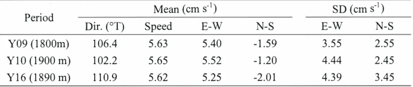
We here focus on the mean flows over the observation periods to investigate the long-term
variation in the deep flow field. The direction and speed of mean flows are ENE (100-1 l 0
°T) and
about 5.6 cm s-1, respectively, in the all observations (Table 1). Furthermore, standard deviations in
each flow component are almost the same among the observations. This indicates that the condition
of mean flows in this area is near! y same between the periods of 2009-2011 and 2016-201 7, though
the warming of deep water in the Yamato Basin is confirmed by some hydrographic observations.
In the eastern Japan Basin, the northern J ap血East Sea, a significant change in the mean
flow is reported (Senjyu, personal communication). To clarify the relationship between the long-term
changes in flow field and oceanic structure, we need more detailed observations.
37 30' 3T20' 37 10' 135'10' 15 R16 135'20' 135"30' 135'40'
Fig. 1 Map of observation site in 2016
10手Y09 (1800
m) ‘―` 5゜
-5 ー10
ー15ー
155
10---
5>-I-
0 (.) -50 -10
_J u」-15MAY JUN JUL AUG SEP OCT NOV DEC JAN FEB MAR APR MAY
2009
I
2010
>
MAY JUN JUL AUG SEP OCT NOV DEC JAN FEB MAR APR MAY2010
I
2011
1510
J
Y16 (1890
m) 5゜
-5 -10 -15MAY JUN JUL AUG SEP OCT NOV DEC
I
JAN FEB MAR APR MAY2016
2017
Fig. 2 Stick diagrams of flows at Sta. Y.
Table 1 Direction and speed of mean flows and standard deviations of each component
Period
Dir. (
0Mean (cm s-
1)
SD (cm s
―1)
T)
Speed
E-W
N-S
E-W
N-S
Y09 (1800m)
106.4
5.63
5.40
-1.59
3.55
2.55
YlO (1900 m)
102.2
5.65
5.52
-1.20
4.44
2.45
No. 19
タイトル:
研究代表者:
所内世話人:
実施期間:
概要:
国際化推進共同研究概要
Mode I inter-comparison study of I ong-range chem i ca I
transport mode I to have a better understanding of PM2. 5
issue over East Asia
Zifa WANG
鵜野 伊津志
2017年11月3日-11月8日、2018年3月13日-3月14日、
2015年3月末から4月初めに北京市内で観測された黄砂と大気汚染粒子の混
合状態の観測結果と、同期間を対象としたモデル解析結果をNatureScientific
Reportに論文として発表した。
中国華北平原から北京にかけて観測される高濃度のPM2.5汚染とその越境影
響について、野外観測結果の解析と複数の化学輸送モデルを用いた 相互比較実
験の取りまとめを進め、2018年3月13日-3月14日にアジア大気汚染研究セ
ンタ
ー(新潟市)と共同で、日本
・中国
・韓国
・アメリカ合衆国・ベトナム
・タイなどからの約5 0名の研究者が参加するMICS - Asiaモデル相互比較国際
ワ
ークショップを九州大学筑紫キャンパスで開催する。
国際化推進共同研究概要
No.21
タイトル:
Dynamical mechanisms of stratospheric control on the tropical troposphere and ocean
研究代表者:
Ueyama, Rei
所内世話人:
江口 菜穂
概要:
1990年代後半から現在における熱帯の大循環場の変化を気象デ
ータ(人工衛星、客観
解析等)を用いて解析を行った。特にここ30年間で北半球夏季に南東太平洋の水温の低
下がみられ、それは赤道をまたぐ南西風の強化、すなわち対流圏内の南北循環場
(Hadley循環;HD循環)が北側ヘシフトしたことに起因することがわかった。さらにHD循環
の強化が、近年の温室効果気体の増加による成層圏の寒冷化によって変詞をきたした成
層圏の南北循環場(Brewer-Dobson循環)と関係することが示唆された。
Dynamical Mechanisms of Stratospheric Control on the Tropical Troposphere and Ocean Rei Ueyama (NASA Ames Research Center) I. Abstract
The cause of recent (from the mid to late 1990s) decadal variations in tropical circulation is studied by making use of a meteorological reanalysis dataset. Cooling of the equatorial southeastern Pacific Ocean occurred in association with enhanced cross
equatorial southerlies, which resulted from a strengthening and poleward shift of the rising branch of the boreal summer Hadley circulation connected to the stratospheric Brewer Dobson circulation. From boreal summer to winter, the anomalous convective activity center moves southward following the seasonal march to the equatorial Indian Ocean Maritime Continent region, which strengthens the surface easterlies over the equatorial central Pacific. Accordingly, ocean surface cooling extends over the equatorial central Pacific. We hypothesize that the fundamental factor causing the recent decadal change in the tropical troposphere and the ocean is a poleward shift of the rising branch of the summertime Hadley cell, which can result from a strengthening of extreme deep convection penetrating into the tropical tropopause layer (TTL), in particular over the continents of Africa and Asia, and adjacent oceans. We conjecture that this effect is produced by a
combination of land surface warming due to increased CO2 and a reduction of static stability in the tropical tropopause layer due to tropical stratospheric cooling.
II. Introduction
Large changes in tropical circulation occurred from the mid to late 1990s. These include (i) a slowdown, or hiatus, of global warming in association with a decrease in the tropical eastern Pacific sea surface temperature (SST), UO the advancement of the onset of the Asian summer monsoon, and (iiO an increase in precipitation in western Africa over the Sahel and in southern Africa during the austral summer. Besides the large-scale circulation changes, mesoscale phenomena such as an increase in the cyclone frequency and intensity over the Arabian Sea were also reported. Wang et al. (2012) argued that these phenomena are related to the early onset of the Asian summer monsoon. Several studies have also shown a relationship between changes in the TTL and the tropical troposphere, namely tropical cyclone activity in the Atlantic (Emanuel et al嘗,2013) and the intensity of tropical storms and SSTs (Ramsay, 2013; Wang et al., 2014).
III. Method/Data
Datasets used in this study include JRASS reanalysis, JRASS-AMIP (which uses the same model and boundary conditions as JRASS, but without assimilation of observational data in the atmosphere), outgoing longwave radiation derived from High Resolution Infrared Radiation Sounder, Global Precipitation Climatology Project precipitation, and COBE-1 gridded SST.
IV. Results
Since the mid 1990s, equatorial ocean in the southern hemisphere has cooled in association with a strengthening of cross-equatorial southerlies near the surface. This was induced by a northward shift of convective activity connected to the rising branch of the Hadley circulation and the stratospheric Brewer-Dobson circulation. Water vapor transport by the enhanced cross-equatorial southerlies further amplified the convective activity in the northern hemisphere. An increase in the vertical velocity was most apparent
![Table 1. Detailed information of the carbon fabric [30]](https://thumb-ap.123doks.com/thumbv2/123deta/8471501.1315510/9.893.137.746.174.333/table-detailed-information-carbon-fabric.webp)