IRUCAA@TDC : Stress Distribution in Mandible and Temporomandibular Joint by Mandibular Distraction: A 3-Dimensional Finite-element Analysis
9
0
0
全文
(2) 161. Bull Tokyo Dent Coll (2009) 50(4): 161–168. Original Article. Stress Distribution in Mandible and Temporomandibular Joint by Mandibular Distraction: A 3-Dimensional Finite-element Analysis Hidenori Katada, Tomohisa Arakawa*, Kenichiro Ichimura*, Kenji Sueishi* and Glenn T Sameshima** Department of Orthodontics, Tokyo Dental College Suidobashi Hospital, 2-9-18 Misaki-cho, Chiyoda-ku, Tokyo 101-0061, Japan * Department of Orthodontics, Tokyo Dental College, 1-2-2 Masago, Mihama-ku, Chiba 261-8502, Japan ** Division of Craniofacial Therapeutics and Sciences, University of Southern California, 925 West, 34th Street, DEN312, Los Angeles, CA 90089-0641, USA. Received 8 June, 2009/Accepted for publication 21 July, 2009. Abstract The effects of mandibular distraction on the mandible and its surrounding tissue remain to be clarified. Here, we used a 3-dimensional finite-element method to investigate the effects of unilateral horizontal lengthening of the mandibular body and vertical lengthening of the mandibular ramus on the mandible and temporomandibular joint (TMJ). With horizontal loading that assumed mandibular body lengthening, tensile and compressive stresses were great near the anterior region of the mandibular angle (the loading area). With vertical loading that assumed mandibular ramus lengthening, tensile and compressive stresses were great at the center of the mandibular ramus (the loading area). Under both loading conditions, stress distribution in the TMJ was greater on the loading side than on the non-loading side. With mandibular body lengthening, the center of the mandible deviated in the direction of the non-lengthened side to widen the mandible in the lateral direction. With mandibular ramus lengthening, the occlusal plane tilted in the inferior direction on the lengthened side. In the TMJ, stress was greatest on the affected side during mandibular ramus lengthening, suggesting the need to consider the mandibular condyle on the affected side during this procedure. Key words:. Mandibular distraction—Three-dimensional finite-element method— Temporomandibular joint—Mandibular condyle. Introduction Distraction osteogenesis was developed by Ilizarov11,12) in the 1960s, and by the early 1990s it was beginning to be used in facial surgery.. When compared to conventional mandibular surgery, this method of bone lengthening in the treatment of hypoplastic mandibular ramus due to hemifacial microsomia23) and bilateral mandibular distraction in the treatment of. 161.
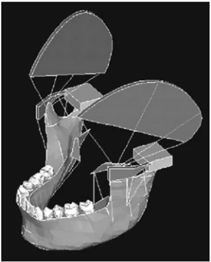
(3) 162. Katada H et al.. micrognathia20) is less invasive and can be performed before the end of the growth period, thus reducing psychological stress13). Moreover, smaller screws that can be placed in the oral cavity have recently been made, and such screws are being more widely used14,22). Therefore, various studies are being performed to ascertain the effects of bone lengthening on the surrounding tissue and examine the direction and design of lengthening screws21). While studies investigating clinical cases and bone lengthening mechanisms are relatively numerous, few 3-dimensional biomechanical studies have been published, and the effects of mandibular distraction on the mandible and its surrounding tissue remain to be clarified. Here, we utilized a 3-dimensional finite-element (FE) method to ascertain the effects of unilateral horizontal lengthening of the mandibular body. Fig. 1 The model of three-dimensional FE method which consists of the bones, muscles, teeth and TMJ. and vertical lengthening of the mandibular ramus on the mandible.. Materials and Methods 1. Preparation of a finite element model Using a dried human skull with normal permanent dentition, the 3-dimensional coordinates of the external bone surface were measured to construct a model. Variables included bones (mandible, temporal bone, zygomatic arch, and sphenoid bone), muscles (masseter, temporalis, and medial pterygoid), teeth, periodontium and articular capsules. In addition, by defining the masseter muscle, suspension of the mandible was reproduced. As to the internal structure of the mandible, a 3-dimensional model was constructed based on tomographic scans and cortical bone thickness and cancellous bone distribution as ascertained by previous studies on internal mandibular structures (Fig. 1). Furthermore, the temporomandibular joint (TMJ) disk was recreated between the mandibular fossa and condyle (Fig. 2). The model consisted of 6,943 nodes and 29,708 elements. The material multiplier for each component was determined based on previous reports7,16,31) (Table 1).. Fig. 2 The model of the temporomandibuler joint. Table 1 Structural components and component properties. Teeth Periodontal membrane Cancellous bone Cortical bone Articular disk. Young’s modulus(MPa). Poisson’s Ratio. 70,000 7 7,800 14,000 20. 0.3 0.49 0.35 0.3 0.4.
(4) Stress Distribution by Distraction. 2. Loading and restraint conditions Loading assumed two techniques for bone lengthening, i.e., unilateral mandibular body lengthening and mandibular ramus lengthening. In mandibular body lengthening, the cortical bone of the left side of the mandibular body was cut to a width of 3 mm and removed vertically on the buccolingual side, and, a 1 kg load was applied horizontally in the occlusal plane from the buccal side in opposite directions (Fig. 3). In mandibular ramus lengthening, the cortical bone of the left mandibular ramus was cut to a width of 3 mm and removed horizontally, and a 1 kg load was applied vertically in the occlusal plane from the buccal side in opposite directions (Fig. 4). The junction between the upper surface of the mandibular fossa and the temporal, zygomatic and sphenoid bones were completely restrained, as was upward movement of the occlusal surface. Using the Ansys 5.2 finite-element analysis software, changes in relation to initial loading were investigated in terms of maximum and minimum principal stress distributions in the external bone surface and mandibular condyle.. 163. 1. Principal stress distribution in the external bone surface 1) Loading by mandibular body lengthening With mandibular body lengthening, tensile. stress was greatest near the anterior region of the mandibular angle (the loading area) and weakened with distance from the loading area. On the non-loading side, tensile stress was minimal. Moreover, tensile stress was seen on the internal surface of the mandible, rather than the external surface (Fig. 5). Maximum principal stress was greatest at the anterior loading area (0.108 MPa). Compressive stress was greatest near the anterior region of the mandibular angle (the loading area) and weakened with distance from the loading area. In addition, compressive stress was seen on the external surface of the mandible, rather than the internal surface (Fig. 6). As with maximum principal stress, minimum principal stress was greatest at the anterior loading area (ⳮ0.073 MPa). 2) Loading by mandibular ramus lengthening With mandibular ramus lengthening, tensile stress was greatest at the center of the mandibular ramus (the loading area) and weakened with distance from the loading area. On the non-loading side, stress was placed in the posterior region of the cervical area of the mandibular condyle. Moreover, tensile stress was seen on the internal surface of the mandible, rather than the lateral surface (Fig. 7). Maximum principal stress was greatest at the medial side of the loading area in the inferior direction (0.080 MPa). Compressive stress was the greatest at the center of the mandibular ramus (the loading area) and weakened with distance from the loading area. Furthermore, on the non-loading side,. Fig. 3 To simulate of mandibular body lengthening. Fig. 4 To simulate of mandibular ramus lengthening. Results.
(5) 164. Katada H et al.. Fig. 5 Tensile stress maps of loading by mandibular body lengthening in the external bone surface. Fig. 6 Compressive stress maps of loading by mandibular body lengthening in the external bone surface. Fig. 7 Tensile stress maps of loading by mandibular ramus lengthening in the external bone surface. Fig. 8 Compressive stress maps of loading by mandibular ramus lengthening in the external bone surface. Fig. 9 Tensile stress maps of loading by mandibular body lengthening in the mandibular condyle. Fig. 10 Compressive stress maps of loading by mandibular body lengthening in the mandibular condyle. Fig. 11 Tensile stress maps of loading by mandibular ramus lengthening in the mandibular condyle. Fig. 12 Compressive stress maps of loading by mandibular ramus lengthening in the mandibular condyle.
(6) Stress Distribution by Distraction. stress distribution was seen on the external surface, in particular, the center and notch of the mandible (Fig. 8). Minimum principal stress was highest at the loading area in the inferior direction (ⳮ0.141 MPa). 2. Principal stress distribution in the mandibular condyle 1) Loading by mandibular body lengthening Enlarged principal stress distribution maps of the loading and non-loading sides in the condyle are shown in Figs. 9–12. In addition, because the stress applied to the joint was smaller than that applied to the external bone surface, we have made stress distribution easier to understand by altering the graduation scale. On the loading side, tensile stress was distributed around the upper surface of the articular process, and was concentrated in the anterior to internal regions. On the non-loading side, a similar distribution was seen, but stress was lower (maximum principal stress: 0.129e3 MPa) (Fig. 9). The compressive stress maps show that while compressive stress was not seen overall, it occurred from the posterior to lateral regions on the loading side and at the anterior and posterior internal surface on the non-loading side (minimum principal stress: ⳮ0.152e-3 MPa) (Fig. 10). 2) Loading by mandibular ramus lengthening With mandibular ramus lengthening, tensile stress was distributed strongly in the posteromedial direction on both the loading and non-loading sides, but it was stronger on the loading side (maximum principal stress: 0.183e-2 MPa) (Fig. 11). On both loading and non-loading sides, compressive stress was generally strong, except for in the posterior region, and was particularly strong in the anterior region. However, it was slightly stronger on the loading side when compared to on the non-loading side (minimum principal stress: ⳮ0.943e-3 MPa) (Fig. 12).. Discussion 1. Bone lengthening Distraction osteogenesis was developed by. 165. Ilizarov, a Russian orthopedic surgeon, in the 1960s11,12). The technique was applied in facial surgery in 1992 by McCarthy et al.20) In facial surgery, distraction osteogenesis has been performed for bone lengthening in the treatment of hypoplastic mandibular ramus due to hemifacial microsomia23) and for bilateral mandibular distraction in the treatment of micrognathia. These procedures were initially performed using externally fixed distraction devices20). However, intraoral distraction devices became widely available in Japan from 19964), and once this technique was recognized as a surgical option in the treatment of mandibular deformity, its indications expanded5,14). Mandibular distraction is less invasive than mandibular surgery, and since it can be performed before the end of the growth period, it also enables psychological stress to be reduced25). Moreover, when compared to surgical transfer of the mandible in the anterior direction, the degree of lengthening is greater for mandibular distraction, while the degree of retraction is smaller 8). However, as far as the indications for mandibular distraction are concerned, it is necessary to ascertain the effects of bone lengthening on the surrounding tissue6,9), the direction and design of lengthening screws21), and prevalence of infections from lengthening devices. Furthermore, another operation is needed to remove the devices. Hence, various studies are presently being conducted. In particular, studies conducted on clinical cases and bone lengthening mechanisms have been relatively numerous, and the effects of lengthening on the TMJ have been investigated clinically18). However, in terms of the biomechanics of mandibular distraction, few studies have been published on the following topics: mechanical analysis of fixation devices; establishment of fixation methods and lengthening direction; and mechanical analysis of bone remodeling or the TMJ in the area of lengthening. In particular, there have not been many 3-dimensional biomechanical studies2,19), and the effects of mandibular distraction on the mandible and the surrounding tissue remain to be clarified. Here, we investigated the effects of bone lengthening.
(7) 166. Katada H et al.. on the mandible and mandibular condyle. 2. Simulation results With horizontal loading that simulated mandibular body distraction, both tensile and compressive stresses were strong near the anterior region of the mandibular angle (the loading area) and weakened with distance from the loading area. Moreover, on the non-loading side, tensile stress was seen on the internal surface of the mandible and compressive stress was seen on the external surface, resulting in lateral deformation of the mandible. Therefore, the left side of the mandibular body (the loading area) was stretched, and the center of the mandible subsequently deviated towards the non-lengthening side, resulting in widening of the mandible in the lateral direction. With vertical loading that simulated mandibular ramus lengthening, tensile and compressive stresses were great at the center of the mandibular ramus (the loading area) the mandible, tensile stress was seen in the upper internal surface and compressive stress was seen on the lower external surface, resulting in a bending deformation-like appearance in the inferior direction with mandibular widening. These findings suggest that the loading area (the left mandibular ramus) was stretched, and that the occlusal plane was tilted in ramus was the inferior direction on the lengthening side. No marked difference in the maximum the lengthened side. No marked difference in the maximum principal stress applied to the mandible was apparent, and no marked difference in stress concentration was observed between the two loading techniques. Sumiyoshi30) investigated differences in flexure in relation to length of lengthening pins in mandibular distraction and reported that longer pins were more advantageous. In the present study, fixation pins were not investigated, but deformation due to stress placed on the mandible caused by distraction was seen27). Moreover, Samcbukov et al.28) investigated fixation and distraction directions in two dimensions and suggested the importance of osteotomy of the mandibular ramus due to rotation force applied to the mandibular. condyle. The present study also confirmed stress in the mandibular condyle. In fact, when performing bone lengthening, cortical bone is generally eliminated for fixation, but in the mandible, because of its rich blood flow, an attempt is made to conserve the bone marrow without rupturing the mandibular canal. In order to mobilize the bone fragment, the bone is fractured artificially (greenstick fracture)17). In such cases, stress distribution to the loading area decreases, thus possibly increasing stress concentration to another area. In this study, in terms of stress on the joint, with mandibular body lengthening, tensile stress was seen in the anteromedial direction for both the loading and non-loading sides, but stress was greater for the loading side. In fact, there have been some reports of patients complaining of pain in the temporal muscle or the TMJ several days after bone distraction3,18). However, when compared to surgical procedures, because stress to the joint is more gradual, such pain should be milder1). Sumiyoshi30) conducted a study using a 3-dimensional FE model with multi-layer construction in the sagittal plane and reported potential risks such as articular disk displacement, because horizontal lengthening causes stress concentration in the anterior direction of the mandibular condyle, while vertical lengthening causes stress concentration in the posterior direction. The present study also showed that mandibular body lengthening caused the mandibular condyle to tilt backward, while mandibular ramus lengthening caused the condyle to tilt forward. In other words, with mandibular body lengthening, because stress is applied to the anterior region of the mandibular condyle, the condyle is tilted backward, but with mandibular ramus lengthening, because stress is applied in the posterior direction, the condyle is tilted forward. The influence of distraction osteogenesis on the TMJ has been reported in animal experiments using dogs and sheep10,15,24,26). Thurmuller, using a minipig, reported that changes were more severe at faster distraction.
(8) 167. Stress Distribution by Distraction. rates (4 mm/day) and tended to resolve during neutral fixation when a rate of 1 mm/day was used29). Because bone lengthening is thought to affect the mandibular condyle, it will be necessary to minimize the degree of single lengthening to avoid causing rapid mechanical changes to the TMJ. In recent years, an attempt has been made to minimize the effects on the joint by performing intermaxillary fixation postoperatively by floating the joint on the affected side and inserting the screws while it is in this position32). However, issues such as final joint position remain to be resolved. In the future, in order to further minimize joint stress, it will be necessary to develop screws with which loading can be adjusted in both horizontal and vertical directions in response to 3-dimensional deformation.. Conclusions With mandibular body lengthening, the mandibular body on the lengthened side was stretched and, as a result, the center of the mandible deviated in the direction of the non-lengthened side, thus widening the mandible in the lateral direction. Moreover, with mandibular ramus lengthening, the mandibular ramus was stretched, and while the mandible was widened, bending deformation in the inferior direction occurred, thus causing the occlusal plane to tilt in the inferior direction on the lengthened side. In this study, mandibular body lengthening applied stress to the anterior region of the mandibular condyle, and the condyle tilted backward. On the other hand, mandibular ramus lengthening applied stress to the posterior region of the mandibular condyle, and the condyle tilted forward. This stress was strong on the loading side with mandibular ramus lengthening. These findings suggest the need to monitor the mandibular condyle on the affected side when performing mandibular ramus lengthening.. References 1) Azumi Y, Sugawara J, Takahashi I, Mitani H, Nagasaka H, Kawamura H (2004) Positional and morphologic changes of the mandibular condyle after mandibular distraction osteogenesis in skeletal class II patients. World J Orthod 5:32–39. 2) Basciftci FA, Korkmaz HH, I¸seri H, Malkoç S (2004) Biomechanical evaluation of mandibular midline distraction osteogenesis by using the finite element method. Am J Orthod Dentofacial Orthop 125:706–715. 3) Braum S, Bottrel JA, Legan HL (2002) Condylar displacement related to mandibular symphyseal distraction. Am J Orthod Dentofacial Orthop 121:162–165. 4) Chin M, Toth BA (1996) Distraction osteogenesis in maxillofacial surgery using internal devices: review of five cases. J Oral Maxillofac Surg 54:45–53. 5) Cope JB, Samchukov ML, Cherkashin AM (1999) Mandibular distraction osteogenesis: a historic perspective and future directions. Am J Orthod Dentofacial Orthop 115:448–460. 6) Fisher E, Staffenberg DA, Mccarthy JG, Miller DC, Zeng J (1997) Histopathologic and biochemical changes in the muscles affected by distraction osteogenesis of the mandible. Plast Reconstr Surg 99:366–371. 7) Fukumoto K (1997) Biomechanical study of deformation on the craniofacial complex by maxillary protraction—Analysis by three dimensional finite element method—. Shikwa Gakuho 97:149–166. (in Japanese) 8) Grayson BH, McCormic S, Santiago PE, McCarthy JG (1997) Vector of device placement and trajectory of mandibular distraction. J Craniofac Surg 8:473–482. 9) Hagino H, Sawaki Y, Ueda M (2001) The fate of developing teeth in mandibular lengthening by distraction: an experimental study. J Craniomaxillofac Surg 29:94–99. 10) Harper RP, Bell WH, Hinton RB, Cherkashin AM, Samchukov ML (1997) Reactive changes in the temporomandibular joint after mandibular midline osteodistraction. Br J Oral Maxillofac Surg 36:20–25. 11) Ilizarov GA (1989) The tension-stress effect on the genesis and growth of tissues. Part I. The influence of stability of fixation and soft-tissue preservation. Clin Orthop Relat Res 238:249– 281. 12) Ilizarov GA (1989) The tension-stress effect on the genesis and growth of tissues. Part II. The influence of the rate and frequency of distraction. Clin Orthop Relat Res 239:263–285. 13) Imola MJ, Hamlar DD, Thatcher G,.
(9) 168. 14) 15). 16). 17). 18). 19). 20). 21). 22) 23). 24). Katada H et al.. Chowdhury K (2002) The Versatility of distraction osteogenesis in craniofacial surgery. Arch Facial Plast Surg 4:8–19. Ito G, Ueda M, Takato T (1999) Distraction Osteogenesis, 1st ed., pp. 16–31, Quintessence Publishing, Tokyo. (in Japanese) Karaharju-Suvanto T, Peltonen J, Laitinen O, Kahri A (1996) The effect of gradual distraction of the mandible on the sheep temporomandibular joint. Int J Oral Maxillofac Surg 25: 152–156. Katada H, Katada H, Isshiki Y (2005) Changes in orthodontic cephalometric reference points on application of orthopedic force to jaw — Three dimensional finite element analysis —. Bull Tokyo Dent Coll 46:59–65. Kawakami S, Mitugi M (2001) Distraction osteogenesis for the orthodontic treatment (3)— Distraction osteogenesis for the treatment of mandibular deficiencies —. J Orthod Pract 5:67–78. (in Japanese) Kewitt GF, Van Sickels JE (1999) Long-term effect of mandibular midline distraction osteogenesis on the status of the temporomandibular joint, teeth, periodontal structures, and neurosensory function. J Oral Maxillofac Surg 57:1419–1425. Kofod T, Cattaneo PM, Dalstra M, Melsen B (2005) Three-dimensional finite element analysis of mandible and temporomandibular joint during ramus elongation by distraction osteogenesis. J Craniofac Surg 16:586–593. McCarthy JG, Schreiber J, Karp N, Thorne CH, Grayson BH (1992) Lengthening the human mandible by gradual distraction. Plast Reconstr Surg 89:1–8. McCarthy JG, Williams JK, Grayson BH, Crombie JS (1998) Controlled Multiplanar distraction of the mandible: device development and clinical application. J Craniofac Surg 9:322–329. Mitugi M (2001) Distraction osteogenesis for the orthodontic treatment (1). J Orthod Pract 3:11–16. (in Japanese) Molina F, Monasterio FO (1995) Mandibular elongation and remodeling by distraction: A farewell to major osteotomies. Plast Reconstr Surg 96:825–840. Ploder O, Mayr W, Schnetz G, Ewers R, Plenk H Jr (1999) Mandibular lengthening with an. 25). 26). 27). 28). 29). 30) 31). 32). implanted motor-driven device: preliminary study in sheep. Br J Oral Maxillofac Surg 37:273–276. Polley JW, Figueroa AA (1997) Management of severe maxillary deficiency in childhood and adolescence through distraction osteogenesis with an external, adjustable, rigid distraction device. J Craniofac Surg 8:181–185. Rabie ABM, Zhao Z, Shen G, Hagg EU, Robinson W (2001) Osteogenesis in the glenoid fossa in response to mandibular advancement. Am J Orthod Dentofacial Orthop 119: 390–400. Ryoyama D, Sawaki Y, Ueda M (2004) Experimental study of mechanical analysis in mandibular lengthening. Application of strain gauge measurement. Int J Oral Maxillofac Surg 33:294–300. Samcbukov ML, Cope JB, Harper RP, Ross JD (1998) Biomechanical considerations of mandibular lengthening and widening by gradual distraction using a computer model. J Oral Maxillofac Surg 56:51–59. Stelnicki EJ, Stucki-McCormick SU, Rowe N, McCarthy JG (2001) Remodeling of the temporomandibular joint following mandibular distraction osteogenesis in the transverse dimension. Plast Reconstr Surg 10:647–658. Sumiyoshi S (1998) Biomechanics simulation of the temporomandibular joint. Jpn J Oral Maxillofac Surg 44:168–182. (in Japanese) Tamatu Y (1994) A measurement of local elastic modulus of labial and buccal compact bone of human mandible. Jpn J Oral Biol 36:306– 329. (in Japanese) Thurmüller P, Troulis MJ, Rosenberg A, Kaban LB (2002) Changes in the condyle and disc in response to distraction osteogenesis of the minipig mandible. J Oral Maxillofac Surg 60:1327–1333.. Reprint requests to: Dr. Hidenori Katada Department of Orthodontics, Tokyo Dental College Suidobashi Hospital 2-9-18 Misaki-cho, Chiyoda-ku, Tokyo 101-0061, Japan.
(10)
図

関連したドキュメント
By interpreting the Hilbert series with respect to a multipartition degree of certain (diagonal) invariant and coinvariant algebras in terms of (descents of) tableaux and
This paper develops a recursion formula for the conditional moments of the area under the absolute value of Brownian bridge given the local time at 0.. The method of power series
We present sufficient conditions for the existence of solutions to Neu- mann and periodic boundary-value problems for some class of quasilinear ordinary differential equations.. We
Then it follows immediately from a suitable version of “Hensel’s Lemma” [cf., e.g., the argument of [4], Lemma 2.1] that S may be obtained, as the notation suggests, as the m A
The proof uses a set up of Seiberg Witten theory that replaces generic metrics by the construction of a localised Euler class of an infinite dimensional bundle with a Fredholm
Using the batch Markovian arrival process, the formulas for the average number of losses in a finite time interval and the stationary loss ratio are shown.. In addition,
[Mag3] , Painlev´ e-type differential equations for the recurrence coefficients of semi- classical orthogonal polynomials, J. Zaslavsky , Asymptotic expansions of ratios of
While conducting an experiment regarding fetal move- ments as a result of Pulsed Wave Doppler (PWD) ultrasound, [8] we encountered the severe artifacts in the acquired image2.
