Architectures and Dynamic Bandwidth Allocation
Algorithms for Passive Optical Hybrid Networks
March 2014
Monir Hossen
Architectures and Dynamic Bandwidth Allocation
Algorithms for Passive Optical Hybrid Networks
山梨大学大学院
医学工学総合教育部
博士課程学位論文
March 2014
Monir Hossen
Architectures and Dynamic Bandwidth Allocation
Algorithms for Passive Optical Hybrid Networks
Supervised by
Prof. Masanori Hanawa
A thesis submitted in fulfillment of the requirement for the award of
the PhD degree
Interdisciplinary Graduate School of Medicine and Engineering
University of Yamanashi, Japan
March 2014
This thesis is dedicated to my beloved wife, son, mother, and father for their absolute love,
encouragement, and expectation on me.
- i -
Acknowledgement
First of all, I am indebted to almighty Allah, because the almighty made me to be a part of that group of people who are inherently ambitious and courageous to face the challenges of the modern technological development.
I would like to express the deepest appreciation and gratefulness to my supervisor, Prof. Masanori Hanawa for his valuable guidance, advice and crucial contribution from the very early stage of this research and for getting admission to this University as a PhD student. In addition, he provided me steady encouragement, excellent academic guidance, and supports in various ways during my study period as a research student. It has been a great pleasure to have him as my PhD supervisor. He has provided me a significant contribution to trigger my intellectual maturity that will be benefited me for a long time. I am also grateful to his family for providing every support to survive me and my family in Japan.
I gratefully acknowledge all the members of my PhD dissertation committee for reviewing this dissertation and providing some constructive comments. I am thankful to them that in the midst of all activities, they have agreed to be one of the members of the evaluation committee.
I am heartily thankful to Japan student service organization (JASSO) and Rotary Yonyama scholarship foundation for providing me a scholarship throughout my study period in Japan. I am also obliged to the authority of University of Yamanashi and Japanese government for giving me the opportunity to study in Japan.
It is a pleasure for me to pay tribute to the authority of Khulna University of Engineering & Technology (KUET), Bangladesh for providing me the study leave to study in the University of Yamanashi, Japan.
I would like to thank my beloved wife, son, mother, father, brothers, relatives, teachers, and friends for their continuous love, sacrifice, encouragement, and faith in me during my study period in Japan.
Collective and individual acknowledgements are also owed to all the members of the Internetworking and Communication Systems Lab., Dr. Okamura, Dr. Nakamura, Mr. Hagihara, Mr. Iijima, Mr. Mizukami, Mr. Mizukoshi, and Mr. Matsushita for their friendship and enormous help during last three years. I was exceptionally fortunate and grateful in having Dr. Okamura, Mr. Hagihara, Mr. Iijima, and Mr. Mizukami for their enormous help and friendly cooperation and sharing various thoughts during the discussion.
- ii -
Finally, my thanks go in particular to Dr. Ahsan Habib, Dr. Jahangir Masud and his family, Dr. Mridul Kanti Mandal and his family, Mr. Matiur Rahman, Mr. Obaidur Rahman, Mr. Mirza Rubel and his wife, Mr. Mukter Hossain, Mr. Anwar Hossain, Mr. Rana and other friends in Japan for their valuable suggestions, company, and help during my PhD study, as well as expressing my apology that I could not mention personally one by one.
- iii -
Table of Contents
1. Introduction
……...………...11.1 What is Hybrid Networks ………1
1.2 Necessity of the Hybrid Networks ………..………2
1.3 Bandwidth Allocation Algorithms in Passive Optical Network (PON) …………..…… ...4
1.3.1 Fixed bandwidth allocation (FBA) algorithm ………...4
1.3.2 Dynamic bandwidth allocation (DBA) algorithm ……….5
1.3.3 Comparisons between the FBA and the DBA algorithms ……….6
1.4 Thesis Outline ………..………8
2.
Overview of PONs and DBA Algorithms
……...………...………..102.1 PONs...………...10
2.1.1 Time Division Multiplexing (TDM) PON ………...12
2.1.2 Wavelength Division Multiplexing (WDM) PON ………..…13
2.1.3 Gigabit PON (GPON) ……….….14
2.1.4 Next Generation PON (NGPON) ………...………….14
2.2 DBA Algorithms ………16
2.2.1 Limited Service (LS) Scheme ………..………...16
2.2.2 Excessive Bandwidth Reallocation (EBR) Scheme ………....16
2.2.3 Limited Sharing with Traffic Prediction (LSTP) Scheme ………...………17
2.2.4 Early DBA (E-DBA) Scheme ………..………17
2.3 Conclusions ………..……….19
3. Architectures of PON-Based Hybrid Networks
………..… 203.1 Single-Optical Line Terminal (Single-OLT) PON-Based Fiber to the Home (FTTH) and Wireless Sensor Networks (WSNs) ………..……….20
3.1.1 Network architecture of a single-OLT PON-based FTTH and WSNs ……….20
3.1.2 Multi-point control protocol (MPCP) for a single-OLT hybrid PON ………..21
3.1.3 Guard time management in a single-OLT PON ……….…………..22
3.1.4 Gate message scheduling algorithm in a single-OLT PON ……….23
3.2 Multi-OLT PON-Based FTTH and WSNs ……….………..25
- iv -
3.2.2 MPCP for a multi-OLT hybrid PON ………...……….27
3.2.3 Guard time management in a multi-OLT hybrid PON ………28
3.2.4 Interleaved polling algorithm in a multi-OLT hybrid PON …….………...……….29
3.2.5 Gate message scheduling algorithm in a multi-OLT hybrid PON .………..31
3.3 Conclusions ……….. 33
4. DBA Algorithms for the PON-Based Hybrid Networks
……….. 344.1 Adaptive Limited DBA (ALDBA) Algorithms for the Single-OLT hybrid PON ………34
4.1.1 Downstream and upstream frame formats in a single-OLT hybrid PON …………35
4.1.2 ALDBA1 scheme ………...……….37
4.1.3 ALDBA2 scheme ……….39
4.2 Adaptive Limited DBA Algorithm for the Multi-OLT hybrid PON (ALDBAM) ………43
4.2.1 Downstream and upstream frame formats in a multi-OLT hybrid PON...…...……43
4.2.2 ALDBAM scheme ………...………45
4.3 Conclusions ………...………50
5. Performance Analysis and Simulation Results of the Proposed DBA
Schemes
.………..…………..……….…... 515.1 Performance Analysis of the ALDBA1 Scheme ………..……….51
5.1.1 Delay ………52
5.1.2 Bandwidth utilization ………..………54
5.1.3 Upstream efficiency ……….………56
5.1.4 Jitter ……….58
5.1.5 Throughput ………..59
5.2 Performance Analysis of the ALDBA2 Scheme ………...61
5.2.1 Delay ………61
5.2.2 Bandwidth utilization ………..………63
5.2.3 Upstream efficiency ……….………65
5.2.4 Jitter ……….67
5.2.5 Throughput ………..68
5.3 Performance Analysis of the ALDBAM Scheme ……….……71
5.3.1 Delay ………72
5.3.2 Bandwidth utilization ………..74
5.3.3 Upstream efficiency ……….76
5.3.4 Jitter ……….78
- v -
5.4 Comparisons Among the LS, EBR, ALDBA1, ALDBA2, and ALDBAM Schemes …...83
5.5 Conclusions ……….………..86
6. Architectures of PON-Based Open Access Networks
……….…….. 886.1 Open Access Networks (OANs) ………..………..88
6.2 Single-OLT PON-Based OAN (S-OAN) ………..……….….. 89
6.3 Multi-OLT PON-Based OAN ( M-OAN) ……….90
6.3.1 Network architecture of an M-OAN ………90
6.3.2 Upstream frame format of an M-OAN for the LS scheme ………..91
6.3.3 Timing diagram of an M-OAN ………...……….92
6.4 Multi-OLT and Multi-Wavelength PON-Based OAN (MM-OAN) ……….94
6.4.1 Network architecture of an MM-OAN ………....94
6.4.2 Upstream frame format of an MM-OAN ………95
6.4.3 Timing diagram of an MM-OAN ………96
6.4.4 Internal buffer architectures of an MM-OAN ……….96
6.5 Conclusions ………...………99
7. Performance Analysis and Simulation Results of the Proposed PON-
Based OANs
……….……….1007.1 Performance Analysis of the M-OAN ………...……..100
7.1.1 Delay ……….……….101
7.1.2 Bandwidth utilization ………..………..102
7.1.3 Overhead to data ratio ………104
7.1.4 Upstream efficiency ………...………105
7.1.5 Jitter ……….………..106
7.1.6 Throughput ………...……….107
7.2 Performance Analysis of the MM-OAN ……….109
7.2.1 Bandwidth utilization ………110
7.2.2 Overhead to bandwidth ratio ……….111
7.2.3 Upstream efficiency ………...………112
7.2.4 Jitter ………..……….113
7.2.5 Throughput ………...……….114
7.3 Comparisons among the S-OAN, M-OAN, and MM-OAN ………..……….115
7.4 Conclusions ……….117
- vi -
References
……….……...…...…………..…..……..…..…..………..… 122List of Publications
……….…..…129- vii -
List of Figures
Fig. 1.1 Illustrative example of a cluster-based WSN…………...………...…………. 2
Fig. 1.2 Illustrative example of an FBA scheme………..…………...………4
Fig. 1.3 Illustrative example of a DBA scheme………...………...………5
Fig. 1.4 Outline of the thesis………...………...……….9
Fig. 2.1 Downstream transmissions in a PON………..…10
Fig. 2.2 Upstream transmissions in a PON………...………11
Fig. 2.3 RTT measurement in a PON………...……….12
Fig. 2.4 WDM-PON architecture………..13
Fig. 3.1 Network architecture of a single-OLT hybrid PON with 2 ONUs connected to the FTTH terminals and 2 ONUs connected to the CHs of a WSN……….…21
Fig. 3.2 MPCP operation in a single-OLT PON………..……….22
Fig. 3.3 Guard time management in a single-OLT PON………...…...22
Fig. 3.4 Scheduling diagram of the Gate messages in a single-OLT PON……….………..24
Fig. 3.5 Network structure and data transmission for a hybrid multi-OLT PON……...……….26
Fig. 3.6 MPCP operation in a hybrid multi-OLT PON………...…..27
Fig. 3.7 Guard time management in a multi-OLT PON………..…….28
Fig. 3.8 RTT and data transmission time in a multi-OLT PON………30
Fig. 3.9 Scheduling diagram for a Gate message in a multi-OLT PON………..….31
Fig. 4.1 Downstream frame format of a single-OLT PON………...…35
Fig. 4.2 Upstream frame format of a conventional PON with the LS scheme………...…..36
Fig. 4.3 Upstream frame format for the ALDBA schemes………...………36
Fig. 4.4 Data acquisition in the ONUs and the ALDBA1 principles………38
Fig. 4.5 Illustrated example of the ALDBA1 scheme………..……….39
Fig. 4.6 Data acquisition in the ONUs and the ALDBA2 principles………...….41
Fig. 4.7 Illustrative example of the ALDBA2 scheme…...……….………...………..42
Fig. 4.8 ALDBAM downstream frame format in a multi-OLT hybrid PON………….………..44
Fig. 4.9 ALDBAM upstream frame format in a multi-OLT hybrid PON………....……44
Fig. 4.10 Data acquisition in the ONUs and the ALDBAM principles……….47
Fig. 4.11 Illustrative example of the ALDBAM scheme for the heavily loaded ONUs………48
Fig. 5.1 Average packet delay in a single-OLT PON-based hybrid networks for the LS and ALDBA1 schemes and NFTTH:NWSN = 8:8 ………53
- viii -
Fig. 5.2 Comparison of average packet delay between the LS and ALDBA1 schemes for a 2-ms
cycle time and NFTTH: NWSN = 8:8………...……….. 53
Fig. 5.3 Comparison of average packet delay between the LS and ALDBA1 schemes for a 2-ms cycle time………..………54 Fig. 5.4 Bandwidth utilization in a single-OLT PON-based hybrid networks for the LS and
ALDBA1 schemes and NFTTH:NWSN = 8:8……….55
Fig. 5.5 Comparison of bandwidth utilization between the LS and ALDBA1 schemes for a 2-ms
cycle time and NFTTH: NWSN = 8:8………..………56
Fig. 5.6 Upstream efficiency in a single-OLT PON-based hybrid networks for the LS and
ALDBA1 schemes and NFTTH :NWSN = 8:8……….57
Fig. 5.7 Comparison of upstream efficiency between the LS and ALDBA1 schemes for 2-ms cycle
time and NFTTH: NWSN = 8:8………..………..57
Fig. 5.8 Jitter in a single-OLT PON-based hybrid networks for the LS and ALDBA1 schemes
and NFTTH :NWSN = 8:8………...……….58
Fig. 5.9 Comparison of jitter between the LS and ALDBA1 schemes for a 2-ms cycle time and
NFTTH: NWSN = 8:8………..………59
Fig. 5.10 Throughput in a single-OLT PON-based hybrid networks for the LS and ALDBA1
schemes andNFTTH :NWSN = 8:8………..60
Fig. 5.11 Comparison of throughput between the LS and ALDBA1 schemes for a 2-ms cycle time
and NFTTH: NWSN = 8:8……….………..……….60
Fig. 5.12 Average packet delay in a single-OLT PON-based hybrid networks for the ALDBA1
and ALDBA2 schemes andNFTTH :NWSN = 8:8……….…….62
Fig. 5.13 Comparison of average packet delay between the ALDBA1 and ALDBA2 schemes for
a 2-ms cycle time and NFTTH: NWSN = 8:8………..62
Fig. 5.14 Comparison of average packet delay between the ALDBA1 and ALDBA2 schemes for a 2-ms cycle time………...………...63 Fig. 5.15 Bandwidth utilization in a single-OLT PON-based hybrid networks for the ALDBA1
and ALDBA2 schemes and NFTTH :NWSN = 8:8……….…….64
Fig. 5.16 Comparison of bandwidth utilization between the ALDBA1 and ALDBA2 schemes for
a 2-ms cycle time and NFTTH :NWSN = 8:8………...………65
Fig. 5.17 Upstream efficiency in a single-OLT PON-based hybrid networks for the ALDBA1
and ALDBA2 schemes and NFTTH :NWSN = 8:8………..66
Fig. 5.18 Comparison of upstream efficiency between the ALDBA1 and ALDBA2 schemes for
a 2-ms cycle time and NFTTH :NWSN = 8:8………...………66
Fig. 5.19 Jitter in a single-OLT PON-based hybrid networks for the ALDBA1 and ALDBA2
- ix -
Fig. 5.20 Comparison of jitter between the ALDBA1 and ALDBA2 schemes for a 2-ms cycle
time and NFTTH :NWSN = 8:8……….……….68
Fig. 5.21 Throughput in a single-OLT PON-based hybrid networks for the ALDBA1 and ALDBA2 schemes and NFTTH :NWSN = 8:8………...……69
Fig. 5.22 Comparison of throughput between the ALDBA1 and ALDBA2 schemes for a 2-ms cycle time and NFTTH :NWSN = 8:8……….………69
Fig. 5.23 Average packet delay in ms in a PON-based hybrid networks and NFTTH:NWSN = 16:16…...73
Fig. 5.24 Comparison of average packet delay among the ALDBA1, ALDBA2, and ALDBAM schemes for a 2-ms cycle time………..………74
Fig. 5.25 Bandwidth utilization in a PON-based hybrid networks and NFTTH:NWSN = 16:16…...……75
Fig. 5.26 Comparison of bandwidth utilization among the ALDBA1, ALDBA2, and ALDBAM schemes for a 2-ms cycle time………..…………76
Fig. 5.27 Upstream efficiency in a PON-based hybrid networks and NFTTH:NWSN = 16:16…….……..77
Fig. 5.28 Comparison of bandwidth utilization among the ALDBA1, ALDBA2, and ALDBAM schemes for a 2-ms cycle time………..…78
Fig. 5.29 Jitter in a PON-based hybrid networks and NFTTH:NWSN = 16:16……...………...….79
Fig. 5.30 Comparison of jitter among the ALDBA1, ALDBA2, and ALDBAM schemes for a 2-ms cycle time………...………..80
Fig. 5.31 Throughput in a PON-based hybrid networks and NFTTH: NWSN = 16:16……...………...…..81
Fig. 5.32 Comparison of throughput among the ALDBA1, ALDBA2, and ALDBAM schemes for a 2-ms cycle time………...………..81
Fig. 6.1 Basic diagram of an open access network………...………89
Fig. 6.2 Architecture of a single-OLT PON-based OAN……….…89
Fig. 6.3 Architecture of a multi-OLT PON-based OAN……….………..90
Fig. 6.4 Upstream frame format of an M-OAN for the modified LS scheme…………..………91
Fig. 6.5 Timing diagram of an M-OAN………..………..92
Fig. 6.6 Network architecture of an MM-OAN………...……….94
Fig. 6.7 Upstream frame format of an MM-OAN for the modified LS scheme………..……….95
Fig. 6.8 Timing diagram of an MM-OAN………...……….96
Fig. 6.9 Internal buffer architecture of an ONU for the downstream transmission in an MM-OAN...97
Fig. 6.10 Internal buffer architecture of an ONU for the upstream transmission in an MM-OAN…...98
Fig. 7.1 Delay in a PON-based OAN………...………...………101
Fig. 7.2 Comparison of average packet delay between the S-OAN and M-OAN for a 2-ms cycle time………..102
Fig. 7.3 Bandwidth utilization in a PON-based OAN………...……….…….103
Fig. 7.4 Comparison of bandwidth utilization between the S-OAN and M-OAN for a 2-ms cycle time………....103
- x -
Fig. 7.5 Overhead to data ratio in a PON-based OAN…...……….104 Fig. 7.6 Comparison of overhead to data ratio between the S-OAN and M-OAN for a 2-ms
cycle time………104 Fig. 7.7 Upstream efficiency in a PON-based OAN………...………105 Fig. 7.8 Comparison of upstream efficiency between the S-OAN and M-OAN for a 2-ms
cycle time………106 Fig. 7.9 Jitter in a PON-based OAN………...……...………...…..106 Fig. 7.10 Comparison of jitter between the S-OAN and M-OAN for a 2-ms cycle time……...…….107 Fig. 7.11 Throughput in a PON-based OAN...………...……….107 Fig. 7.12 Comparison of throughput between the S-OAN and M-OAN for a 2-ms cycle time…...108 Fig. 7.13 Bandwidth utilization in the S-OAN, M-OAN, and MM-OAN…………...………...…….110 Fig. 7.14 Overhead to data ratio in the S-OAN, M-OAN, and MM-OAN…...………...………111 Fig. 7.15 Upstream efficiency in the S-OAN, M-OAN, and MM-OAN………...………...………...112 Fig. 7.16 Jitter in the S-OAN, M-OAN, and MM-OAN………...………113 Fig. 7.17 Throughput in the S-OAN, M-OAN, and MM-OAN………...……….114
- xi -
List of Tables
Table 1.1 Comparisons between the FBA and DBA schemes ………7 Table 2.1 Comparisons among the WDM-PON, GPON, and NGPONs………...15 Table 5.1 Simulation parameters used in the single-OLT PON-based FTTH and WSN……...……...52 Table 5.2 Simulation parameters used in the multi-OLT PON-based FTTH and WSN …...………...71 Table 5.3 Comparisons among the LS, EBR, ALDBA1, ALDBA2, and ALDBAM schemes ………85 Table 7.1 Simulation parameters for the M-OAN ………..101 Table 7.2 Simulation parameters for the MM-OAN ………...109 Table 7.3 Comparisons among the S-OAN, M-OAN, and MM-OAN ………...116
- xii -
Abstract
A passive optical network (PON) based hybrid network is a highly capable access network that effectively converge several service providers without suffering from any bandwidth deficiency. Main considerable points to design an efficient PON-based hybrid network are; an effective network architecture for combining several service providers with their own features in a single PON and a suitable dynamic bandwidth allocation (DBA) algorithm. This thesis proposes several PON-based hybrid network architectures, i.e., a single-optical line terminal (single-OLT) PON-based fiber to the home (FTTH) and wireless sensor networks (WSNs), a multi-OLT PON-based FTTH and WSNs, a multi-OLT PON-based open access networks (M-OANs), and a multi-OLT and multi-wavelength PON-based OANs (MM-OANs). A PON-based hybrid network consisting of a single OLT for the multiple service providers increases the computational complexity of data packet processing in the OLT, resulting in a longer time delay and more packet losses. To overcome these problems this thesis proposes a multi-OLT PON-based hybrid networks for reducing the computational complexity of data packet processing in a hybrid network of the multiple service providers. One of the most important issues on designing the hybrid PON is the improvement of bandwidth sharing efficiency in the upstream channel among the multiple service providers having different packet lengths and data rates. In addition to the new architectures of the PON-based hybrid networks this thesis also proposes several new DBA algorithms, i.e., adaptive limited DBA1 (ALDBA1) and ALDBA2 algorithms for the single-OLT PON-based hybrid networks, and an ALDBA algorithm for the multi-OLT PON (ALDBAM) based hybrid networks. All these algorithms consider different maximum upstream transmission windows for the different service providers in the network. The size of a maximum transmission window for a service provider depends on its maximum packet length. The proposed ALDBAM scheme is a modified version of the ALDBA schemes, where both the ALDBA1 and ALDBA2 schemes are combined with proper guard time management and a modified version of the multi-point control protocol (MPCP) in the medium access control layer.
In the usual OANs, several service providers are connected to a single access terminal and the users are able to get any service from those service providers by using a single access terminal. That means the OAN provides a true broadband concept. In this thesis, the proposed M-OAN uses a single PON-based access network with multiple OLTs for the multiple service providers and the proposed MM-OAN uses a single PON-based access network with the multiple OLTs and multiple uplink wavelengths for the multiple service providers. The OLTs of the proposed PON-based OANs are considered as the central offices (COs) while all the ONUs of the proposed PON-based OANs are considered as the access terminals for all the service providers. The multiple OLTs in the M-OAN
- xiii -
share the computational complexity of data packet processing from the multiple service providers that reduces the data processing times as well as the end-to-end packet delay and improves the bandwidth utilization. In addition to those advantages in the M-OAN, the MM-OAN also uses multiple uplink wavelengths where a single upstream channel is successfully overlapped by the simultaneous transmissions of the multiple service providers that improve the upstream efficiency and throughput.
All the proposed DBA algorithms for the PON-based hybrid FTTH and WSNs and the network structures of the OAN of this thesis are studied by laboratory made computer simulation programs. The performances of the ALDBA1 and ALDBA2 schemes are evaluated for a single-OLT PON-based hybrid networks combining the FTTH and WSNs while a multi-OLT PON-based hybrid FTTH and WSNs is considered for the ALDBAM scheme. On the other hand, four different service providers, i.e., FTTH, WSN, high definition television or video on demand, and femto networks are considered in the performance analysis of both the M-OAN and MM-OAN architectures by using a modified version of the limited service (LS) scheme. This thesis also provides some quantitative comparisons among the performances of the proposed and existing DBA schemes even though it is difficult and not fair because the network architectures and simulation environments are not similar among them. The simulation results show that the proposed DBA schemes with the proposed hybrid network architectures of the PON, and the proposed PON-based OANs with a modified version of the LS scheme provide lower packet delay and jitter with higher bandwidth utilization, higher upstream efficiency, and higher throughput than the conventional LS scheme of both the PONs and OANs, respectively. When the performances of the proposed ALDBAM scheme are compared to those of the LS scheme it is found that the ALDBAM scheme provides more than 115% less delay with 40% higher throughput than those of the LS scheme for an offered load of 1.0 and a 2-ms cycle time. On the other hand, the MM-OAN provides more than 400% higher throughput with 50% lower jitter than the single-OLT PON-based OAN for an offered load of 1.0 and a 2-ms cycle time. These results and macro view comparisons with the existing schemes prove the significance and validity of these researches of this thesis.
Key words: hybrid networks, PON, WSN, OAN, FTTH, DBA algorithm, packet delay, jitter,
- 1 -
1. Introduction
This chapter starts with a brief definition of the passive optical network (PON) based hybrid networks. Next, the necessity of the hybrid networks for combining several service providers in a single network architecture with the importance of a new dynamic bandwidth allocation (DBA) algorithm fit for the proposed hybrid network architectures are explained that lead to the motivations of this thesis. Finally, the outline of this thesis is presented.
1.1 What is Hybrid Networks
A hybrid network is a new network concept in the modern information and communication arena. In a hybrid network, two or more different networks or service providers are combined all together with their own features and infrastructures. The hybrid network is a more real life networking topology as it provides reliable and versatile connections and data transmission paths to the users [1]. It provides less installation cost by sharing a single backbone network instead of installing separate network infrastructures for the different networks or service providers.
In a hybrid network, the central office (CO) provides independent connection with the different networks or service providers. That means, in the hybrid network, data transmission of a service provider does not depend on the other service providers. As a result, failure of data transmission from a service provider does hamper the performance of other service providers in the network.
The main drawbacks of a hybrid network are that it is complicated and difficult to diagnose any fault in the network. To overcome the fault diagnosis problem in the hybrid network, intelligent hubs are designed to provide automatic fault isolation and processing [1].
In this thesis, a PON-based hybrid networks is considered where two service providers, i.e., fiber to the home (FTTH) and wireless sensor networks (WSNs), are combined with their own features and infrastructures. This thesis also considers a PON-based open access network (OAN) where four different service providers, i.e., FTTH, WSNs, high definition television or video on demand
- 2 -
1.2 Necessity of the Hybrid Networks
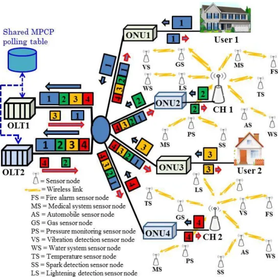
The ubiquitous city (u-City) is an autonomous city. In a u-City, all the information systems and service providers are virtually interlinked together. The convenience of a u-City is that anyone can access any service provider from anywhere in the city by using only one access terminal. Nowadays, the number of different service providers, e.g., FTTH [2,3], WSNs, local area networks (LANs), FNs [4], HDTV/VoD [5,6], and ad-hoc networks, in a u-City has increased dramatically. Although a significant number of service providers providing both the wireless and fiber-based networks already exist in the modern cities, still there is no suitable interlink between the wireless and fiber-based operators. Usually, sensor nodes in a WSN will send notifications to the CO concerning any abnormality of any household or commercial device in a sensor network that is expected to be deployed for all the households and commercial systems in the u-City, e.g., gas systems, temperature and pressure monitoring systems, electric sparking and smoke detection systems, automobile systems, and medical sensor nodes in a hospital. Usually, the WSN service providers use wireless links to connect wireless sensor nodes to a CO, i.e., personal area network coordinator (PANC). In contrast, the optical fiber-based access networks are used for the FTTH terminals. This optical fiber-based network infrastructure has enough bandwidth and that bandwidth can be effectively shared with a WSN without any bandwidth bottlenecks occurring in the access networks. In this case, a cluster-based WSN is important to divide the whole network into several clusters. Moreover, clustering of a WSN effectively reduces the total energy consumption in the network [7,8,9,10]. Figure 1.1 shows an illustrative example of a cluster-based WSN. J. Tang et al. have proposed using a cluster-based WSN to divide the entire sensor network of a u-City and to connect all of the static cluster heads (CHs) to the PANC through a radio-over-fiber (RoF) link [11]. In the RoF based sensor networks static CHs are required to connect the CHs to the fiber. M. Hossen et al. have proposed a cooperative clustering algorithm, where each cluster contains a static CH and each CH is connected with the optical network
- 3 -
units (ONUs) of a PON system through an optical fiber link [12,13]. As the sensor nodes are deployed in a u-City, any sensor node in a home or office can act as a static CH and easily be incorporated into the electric supply system. That is why there is no possibility of an inadequate power supply, unlike the CHs of a typical sensor network. The use of the optical fiber links in a cluster-based WSN in a u-City is very convenient because it will avoid long distance radio frequency (RF) transmissions [12,13], i.e., from the CHs to the PANC, which will reduce the energy consumption of the small battery powered sensor nodes [14].
Moreover, the HDTV/ VoD and FNs in addition with the FTTH and WSNs are also going to be more popular in a modern city. However, constructing a closed, specific-use network for each individual service provider and accommodating several users using different access terminals and servers require an enormous amount of time and expense. To overcome the enormous expense and deployment of several backbone networks, a PON-based hybrid network is an effective solution to comprise all the service providers in a single optical network, because the PON systems can effectively share the upstream channel and the CO equipment over a high-speed and high-capacity bandwidth demands [9]. Also a PON is an inherently cost-effective technology [15] because it does not require active components and remote power facilities. Furthermore, sharing the fiber medium for the several service providers reduces the cost of physically deploying the fiber.
One of the most critical issues for converging the FTTH access networks and several service providers, e.g., WSNs, HDTV/VoD, FNs etc., in a single optical line terminal (single-OLT) PON is the requirement of more computational complexity of data packet processing in the OLT. Because all of these service providers in a u-City have several features, e.g., device capacity diversity, application diversity, mobility, numbering and routing diversity, security, and privacy, they significantly differ from the conventional access networks. This is why the current access network architectures are not capable of integrating these service providers efficiently [16]. To mitigate this problem, some polling algorithms have been proposed to allow additional time in the OLT for computation and management in addition to the guard time between the transmitted data packets from every two successive ONUs [17]. However, this thesis provides a detail PON-based hybrid network architecture that contains multiple OLTs [18, 19, 20] in the CO in addition to the PON-based hybrid network with a single OLT [21] to reduce the computational complexity of data packet processing in the OLT. To show the effectiveness and validity of the proposed time division multiplexing (TDM) PON-based hybrid networks in practical applications new DBA algorithms are required for both the single-OLT and the multi-OLT hybrid PONs. This thesis also presents several new DBA algorithms for the different proposed PON-based hybrid network architectures. The Ethernet-based data packets and TDM-PON principles are considered in all the analysis of this thesis.
- 4 -
1.3 Bandwidth Allocation Algorithm in PON
In the PON systems, each ONU’s upstream bandwidth is decided by allocating time slots specified by the OLT in unit time [22]. Interleaved polling algorithm [13] is a widely used algorithm in which the OLT polls the ONUs individually and issues Gate messages to them in a round-robin fashion. In this algorithm, the OLT maintains a polling table containing the number of bytes waiting in each ONU’s buffer and round-trip-time (RTT) to each ONU. At the end of an upstream transmission window, every ONU informs its queue size to the OLT by a Report message. The main principle of this algorithm is to provide synchronization among the data transmission instants from the multiple ONUs to avoid data collision and to fairly share the upstream channel capacity. The bandwidth allocation algorithm has a major impact on minimizing latency, improving the fairness of bandwidth sharing efficiency, meeting the quality of service (QoS) guarantees, and requirement of buffer size in the upstream direction. In a general sense, bandwidth allocation algorithms can be classified into two major groups; fixed bandwidth allocation (FBA) and DBA algorithms.
1.3.1 Fixed Bandwidth Allocation (FBA) Algorithm
The FBA scheme is a very simple bandwidth allocation algorithm. In the FBA scheme, the OLT ignores the requested window sizes from the ONUs and always grants the maximum transmission windows to all the ONUs, as a result a cycle time Tcycle is a constant for any traffic condition in every time cycle [23]. Here, the Tcycle is a length of a polling cycle in the upstream time cycle of a PON
system. The Tcycle in a PON is defined by the summation of the granted transmission windows to all
the ONUs and total over heads. In this scheme, all traffics are considered to be a single class traffic.
Fig.1.2 Illustrative example of an FBA scheme.
Figure 1.2 shows the illustrative example of an FBA scheme. The main advantages of this scheme are that it requires very low computational complexity and very simple logical operations. However, the main drawbacks of this algorithm are lightly loaded ONUs, the ONUs those have smaller data
- 5 -
packets in the queue, will under utilize their allocated bandwidth leading to increase the end-to-end packet delay to other ONUs and eventually deteriorate the throughput and bandwidth utilization of the system. From the Fig. 1.2 it is obvious that the length of the 1st time cycle Tcycle1 is equal to the
max
cycle
T
where every ONU has a maximum transmission window to transmit. On the other hand, the length of the 2nd time cycle Tcycle2 is also equal to the
max
cycle
T
even though the ONU1 has half of the max and the ONU2 does not have any data to transmit. As a result, some bandwidths are wasted in the 2nd time cycle.1.3.2 Dynamic Bandwidth Allocation (DBA) Algorithm
The DBA algorithms are playing a vital role in distributing the upstream bandwidth to the ONUs of a PON system. The DBA algorithms are suitable for the burst network traffics such as the FTTHs and voice over internet protocol (VoIP). In the DBA schemes, the transmission window of each ONU is upper bounded by the max[24]. When the requested bandwidth by the ONU is less than the max, the OLT grants the requested bandwidth; otherwise, max is granted.
Fig. 1.3 Illustrative example of a DBA scheme.
Figure 1.3 shows an example of bandwidth allocation in a PON using a DBA scheme. In the DBA schemes, since the granted window to an ONU is based on the requested window by that ONU, the
Tcycle is variable. As shown in the figure, the cycle time in the 1st time cycle is
max 1 cycle cycle
T
T
, becauseevery ONU has requested for the maximum bandwidth max. In contrast, the cycle time in the 2nd time cycle is
T
cycle2
T
cyclemax
T
S, here, TS is the cycle time savings due to the lightly loaded ONUs. This scheme reduces the bandwidth wastage by granting smaller bandwidth to the lightly loaded ONUs. However, one limitation of this algorithm is that making the Tcycle too small will cause lower bandwidth utilization, ratio of effective data to the effective data plus overheads, because of the constant guard time between every two successive ONUs and this occurrence is called the light-load- 6 -
penalty. Following equations represent the light-load penalty effect in the PON system using the existing LS DBA scheme:
U C grant cycle
R
NB
N
T
(1.1) C grant grantNB
N
N
BWU
(1.2) where, N represents the number of ONUs, grant is the granted window size for an ONU in a time cycle, RU is the transmission speed, BC is the overhead, i.e., summation of the guard intervals,Ethernet overheads, and Report messages, and BWU is the bandwidth utilization.
From the Eq. 1.1 it is clear that the length of a Tcycle depends on the total granted window size in a
time cycle as the total overhead NBC and transmission speed RU are constant in every time cycle.
Hence, the smaller Tcycle means the smaller total granted windows, i.e., N
grant
, and the smaller Ngrant means lower BWU as shown in the Eq. 1.2.
1.3.3 Comparisons Between the FBA and the DBA Algorithms
In the FBA scheme, a Tcycle is a constant for all the traffic loads in every time cycle. In this case,
data packets suffer from the same delay in every time cycle and it does not depend on the present network traffics. So, it is clear that the length of the Tcycle for the FBA scheme is always equal to the
max
cycle
T
. If the traffic load is very low then the bandwidth utilization problem will be severe in the FBA scheme due to the bandwidth wastages by the Ethernet overheads, Report messages, and guard times. The following formula represents the length of a cycle time for the PON system using the FBA scheme. U eth rep cycle cycleR
P
B
B
N
GI
B
N
T
T
max max
(
)
(
)
(1.3)where, Brep, B, and Beth denote the Report message size, data packet size, and Ethernet overhead,
respectively, GI is the guard interval, N represents the number of ONUs, P max indicates the maximum number of data packets in an ONU.
In the DBA scheme, the Tcycle is variable under the low and non-uniform traffic conditions, since
- 7 -
bandwidth utilization in the DBA scheme is better than that of the FBA scheme due to avoidance of the bandwidth wastages. Equation 1.4 represents the cycle time for the DBA scheme.
U N i i eth rep cycle
R
P
B
B
GI
B
N
T
1)
(
)
(
(1.4)where, Pi is the number of data packets in the queue of the ONU i and Pi ≤ P max.
Table 1.1 shows comparisons between the FBA and DBA schemes in a PON system at a glance. These comparisons show for the non-uniform self-similar network traffics.
Table 1.1 Comparisons between the FBA and DBA schemes
Quantity FBA DBA
Efficiency Inefficient Very efficient
Jitter Lower Higher
Bandwidth utilization Lower Higher
Throughput Lower Higher
Traffic condition Not suitable for burst traffic Suitable for burst traffic
Allocated bandwidth Constant Dynamic
- 8 -
1.4 Thesis Outline
This thesis organized in 8 chapters. Figure1.4 shows the thesis outline in short using a block diagram. In the chapter 2, some theoretical frameworks are explained that is related to the proposed research works. This chapter provides some background on the different PONs and DBA algorithms for general understanding of them. Chapter 3 presents the architectures of the proposed single-OLT and multi-OLT PON-based hybrid networks for comprising the FTTH and WSNs. Chapter 4 provides detailed analysis of the proposed DBA algorithms for the hybrid PONs. Chapter 5 elucidate the performance parameters, methodologies, and comparisons of the proposed DBA schemes to the existing schemes for providing sufficient contributions, significance, and validity of this research. Chapter 6 illuminates two new architectures of the proposed PON-based OANs. In the chapter 7, simulation results of the proposed PON-based OANs have been analyzed using the modified version of the LS scheme. Finally, chapter 8 concludes this thesis by explaining the finding of this research and its importance for the future communication professionals.
- 9 -
- 10 -
2. Overview of PONs and DBA Algorithms
PON is an inherently cost effective technology in the modern communication arena. Application of the PON technology in the communication arena is getting more and more popular due to its bandwidth intensiveness. The DBA algorithm provides a significant contribution in achieving the optimum performance of a PON system. This chapter presents a brief review of the existing PONs and several DBA algorithms.
2.1 PONs
In a PON system, no active elements are used between the CO and the end users in the network, i.e., OLT and ONUs. A PON only contains passive optical components, e.g., optical fibers, combiner/splitters, between the two end points of the network. A PON can be deployed in several network topologies, e.g., tree, ring, and bus [25]. However, tree topology is the most popular one in the PON deployment, where an OLT will be at the root and all the ONUs will be at the tree side [26]. Multiple ONUs are connecting to an OLT through 1:N splitter/combiner. The PON provides bi-directional transmissions between the OLT and ONUs through a single optical fiber link. The MPCP [14, 27] plays a vital role in the avoidance of collisions and the sharing of the single optical fiber link with the multiple ONUs in a tree-based PON topology.
- 11 -
In the downstream direction of a PON, data transmission is broadcasting in nature, i.e., point to multi-point (P2MP), where the Gate messages and data packets are broadcasted from the OLT to all the ONUs. Each ONU accepts the Gate message and data packets from the OLT according to the destination address. Figure 2.1 shows the downstream data transmission in a PON system. Here, an OLT broadcasts the downstream data packet to the N ONUs connected to the FTTH terminals. The downstream data packets from the OLT are multiplexed in a TDM principle. The main information contained in a downstream packet is the upstream transmission time and the length of the transmission window of each ONU.
Fig. 2.2 Upstream transmissions in a PON.
In an upstream direction, a PON is a multi-point to point (MP2P) network [23] where all the ONUs share a common channel to transmit their data packets to the OLT. Figure 2.2 shows the upstream data transmission in a PON system. Here, every ONU transmits its upstream data packets in a specific time slot allocated by the OLT. The upstream data packets from the entire ONUs are combined together in the splitter/comber and then transmit to the OLT.
Data transmissions of a PON in both the upstream and downstream directions are controlled by a DBA algorithm and the MPCP. The MPCP is a two-way messaging protocol defined to arbitrate the simultaneous transmissions of different ONUs and resides at the medium access control (MAC) layer. The MPCP relies on two control messages, Report and Gate, in its regular operation. In this protocol, auto discovery mode is used to connect and detect a newly activated ONU in the network and to calculate the RTT delay and to assign the MAC address of that ONU. In the MPCP of the PON system, the RTT is used to schedule the control messages: the Gate message from the OLT to ONUs and the Report message from the ONUs to the OLT. The RTT depends on the physical distance from the OLT to an ONU and the OLT maintains a polling table to store the RTT of every ONU.
- 12 -
Fig. 2.3 RTT measurement in a PON.
Figure 2.3 shows a diagram of the RTT measurement in a PON system. The OLT first initiates the RTT measurement process by sending a Gate message to an ONU. Here, the Gate message Gi is sent
to the ONU i at an absolute time T1 and the ONU i receives the Gate message at a time instant T2. After receiving the Gate message every ONU requires sometimes for identifying the MAC address and processing the Report message. At a time instant T3 the ONU i transmits a Report message Ri that
is accepted by the OLT at a time instant T4. The following equation is used to calculate the RTT of the ONU i.
)
(
)
(
T
4T
1T
3T
2RTT
i
(2.1) here, RTTi is the RTT delay of the ONU i.Several variants of the PON have been established in the modern communication technology, e.g., TDM-PON, Wavelength division multiplexing PON (WDM-PON), Gigabit PON (GPON), and next generation PON (NGPON).
2.1.1 Time Division Multiplexing PON (TDM-PON)
In the TDM-PON, a single upstream channel is shared by several ONUs in the network [23, 28]. The OLT is responsible for allocating the upstream bandwidth to the ONUs. However, the downstream transmission is broadcasting in nature. In the TDM-PON, a bandwidth allocation algorithm is required for efficient distribution of the single upstream channel. For perfect scheduling of data transmission from the different ONUs a polling algorithm is also required in addition to the bandwidth allocation algorithm. Usually, polling algorithm is a cycle based protocol, which used to avoid high traffic load, data collision, and limits the maximum transmission window for each ONU. A
- 13 -
commonly used polling algorithm is the round-robin, which orders the data transmission from every ONU in a periodic way. To improve the network performance, interleaved polling with adaptive cycle time (IPACT) [17] is used. The interleaved polling algorithm can also have different policies, such as an interleaved polling algorithm with and without stop polling. In all the interleaved polling algorithms, the OLT contains a polling table which provides information about the RTT to the entire ONUs and their granted window sizes. Additionally, a guard time is used between every two successive ONUs to avoid overlapping of the transmission windows by fluctuations in the RTT calculation [29] and on/off timing of the lasers in both the OLT and ONUs.
2.1.2 Wavelength Division Multiplexing PON (WDM-PON)
Nowadays, the WDM-PON is considered as the most popular next generation access technology by many service providers. In the WDM-PON, several optical carriers are multiplexed together by using different wavelengths and then transmitted through a single optical fiber in both the directions, i.e., upstream and downstream, between the OLT and ONUs. There is no doubt that the TDM-PON is an excellent solution to overcome the problems associated with the copper-based access networks [30]. However, for providing further improvement in terms of bandwidth the WDM-PON has been proposed in the mid-1990s.
Fig. 2.4 WDM-PON architecture.
Figure 2.4 shows a typical architecture of a WDM-PON. In the downstream direction of the WDM-PON, several wavelengths are combined in an arrayed waveguide grating (AWG) placed in the OLT then another AWG is placed in the remote node (RN) that filters a specific wavelength and guided to a specific ONU through an optical fiber. Here, the OLT contains a multi-wavelength source for transmitting multiple wavelengths to different ONUs [30] where the number of wavelengths is equal to the number of ONUs in the network. In the upstream direction of the WDM-PON, the OLT
- 14 -
receives different wavelengths from the different ONUs by using a receiver array and a WDM demultiplexer.
In the WDM-PON, a simplified MAC layer is used because it does not require any complicated DBA algorithm. However, a DBA algorithm has been proposed which is called WDM-PON DBA [31] for increasing throughput of the WDM-PON by finding an appropriate wavelength for each traffic. To implement this DBA in the WDM-PON, the MPCP of the TDM-PON is upgraded that assigns both the time slots and wavelengths [32].
2.1.3 Gigabit PON (GPON)
The international telecommunication union (ITU) has recommended G.984.x series for the GPON standard [33, 34, 35]. In this standard, several upstream and downstream data rates up to 2.48832 Gbps are specified [36]. The GPON provides high-speed and high-bandwidth for voice, data, and video services to both the residential and business subscribers. The GPON also provides a cost effective solution for the FTTH services [37, 38]. The GPON uses Ethernet frame fragmentation scheme to encapsulate the data packets and the Ethernet headers called general encapsulation method (GEM). The GEM transport layer supports asynchronous transfer mode (ATM), the Ethernet, and the TDM data transport. The GPON uses different status reporting mode to provide a simple and efficient means of setting up a system for multiple service classes [36]. The basic GPON systems support a maximum physical reach of 20km on a 32-way splits or 10km on a 64-way splits. However, fiber and optical amplifiers can be used to extend the reach of a GPON system with a 64-way splits to 60km [39].
In the downstream transmission of the GPON, the maximum data rate is 2.4 Gbps. That means the bandwidth for each optical network terminal (ONT) is sufficient to support the multiple HDTV signals. It provides a very high level of QoS support that is suitable for the delay sensitive traffics, e.g., voice traffic and real time video streaming.
In the upstream transmission of the GPON, the maximum data rate is 1.24 Gbps and the minimum bandwidth for each ONT can be guaranteed. The unused timeslots can be assigned to the heavily loaded users. The QoS is also allowed for the delay sensitive traffics.
2.1.4 Next Generation PON (NGPON)
In the NGPON both the EPON and the GPON systems are expected to be coexisted for the foreseeable future in the modern communication area [40]. To meet the ever increasing demands for high bandwidth requirements from the end users, the 10G EPON task force was formed, known as IEEE 802.3av [41]. However, the full service access network (FSAN), a standardization organization, has introduced the NGPON to achieve higher performance parameters, e.g., high bandwidth,
- 15 -
increased split ratio, and extended maximum reach, than the existing EPON and GPON [42]. The NGPON is primarily divided into two phases, e.g., NGPON1 and NGPON2. The NGPON1 is a midterm upgradation of the typical PON system where its major requirements have been coexisted with that of the GPON and reuse of the outside plant. In contrast the NGPON2 is a long-term solution in the PON evolution. A most important requirement of the NGPON1 is to provide higher data transmission rates than the GPON. In addition, the operators expect that the NGPON1 will leverage the existing optical deployments. Hence, the FSAN and ITU Telecommunication (ITU-T) specified the NGPON1 backward compatibility with the existing GPON deployments to protect the initial GPON investments of the operators [43]. Table 2.1 shows comparisons among the GPON, WDM-PON, and NGPONs.
Table 2.1 Comparisons among WDM-PON, GPON, and NGPONs.
Quantity WDM-PON GPON NGPON1 NGPON2
Standards None ITU G.984 FSAN FSAN
Framing
Protocol
Independent GEM GEM
GEM
Maximum Bandwidth 1-10 Gbps/channel 2.5Gbps 1.25Gbps
10Gbps
2.5Gbps 10Gbps
Users per PON 16-32 32-64 ≥64 ≥64
- 16 -
2.2 DBA Algorithms
DBA algorithms are playing a vital role in distributing the upstream bandwidth to the ONUs in the TDM-PON. Intensive researches have been conducted on the DBA algorithms over a PON [17,24,26,29,44,45,46,47,48,49,50,51,52] and among them, the popular schemes are the limited service (LS) [17], excessive bandwidth reallocation (EBR) [29], limited sharing with traffic prediction (LSTP) [51], and early DBA (E-DBA) [52] schemes.
2.2.1 Limited Service (LS) Scheme
In the LS scheme, the granted time slot length for an ONU depends on the dynamic network traffic and the maximum length of a transmission window is upper-bounded by the max. If the requested bandwidth
Ri by the ith ONU is less than the max then the granted bandwidth from the OLT is equal to the
iR. In contrast, if the
Ri is greater than or equal to the max then the granted bandwidth from the OLT is equal to the max . Equation 2.2 shows the bandwidth allocation formula for the LS scheme. This scheme mainly depends on the control messages, e.g., Gate and Report messages, defined by the MPCP [53] to track the traffic load of each ONU and to expedite the bandwidth negotiation.
R max i max max R iif
if
R i G i (2.2)where
Gi is the granted bandwidth to the ONU i by the OLT.The main disadvantage of this scheme is that it does not consider the arriving data traffics during the waiting time, the time between the transmission of the Report message from an ONU and the reception of the Gate message from the OLT. That is why, this scheme is not suitable for the delay and jitter sensitive services because of the variable length of polling cycle.
2.2.2 Excessive Bandwidth Reallocation (EBR) Scheme
This scheme proposed to divide the total ONUs in a network into two groups depending on the accumulated data packets in the queue of an ONU called heavily loaded ONUs and lightly loaded ONUs. One of the main objectives of this scheme is to avoid the light-load penalty. This algorithm also supports differentiated services by employing a suitable intra-ONU priority scheduling scheme. This scheme provides better bandwidth utilization by utilizing the excessive bandwidth from the lightly loaded ONUs to the heavily loaded ONUs.
- 17 -
Priority queuing is a useful and simple method for supporting the differentiating service classes [27]. In this scheme, each ONU maintains three different priority queues with same buffering space. First, the incoming packets are classified and placed in their appropriate priority queues. According to the rule of this scheme, if a packet arrives with the higher priority but finds that the high priority buffer is already full, then it stores at a lower priority queue. In contrast, if a lower priority packet arrives and the lower priority queue is full, then the packet is dropped. Three priority groups are specified as high-priority Hi, medium-priority Mi, and low-priority Li and the ONU can transmit the
bandwidth request for every priority group individually by using the MPCP Report messages. Note that the MPCP can reports up to eight priority queues [14,54]. On the other hand, the OLT generates three different Gate messages to respond to the Report messages of the three traffic classes as
H
iG,G i
M
,L
Gi , respectively.2.2.3 Limited Sharing with Traffic Prediction (LSTP) Scheme
The LSTP scheme supports dynamic bandwidth negotiation between the OLT and ONUs. The end-to-end packet delay is reduced by predicting the deferred traffic that arrives during the waiting time between the transmission of the Report message from an ONU and the reception of a Gate message from the OLT. This scheme also provides an option to preserve some bandwidth for delivering the data packets during the waiting time.
The bandwidth negotiation between the OLT and the ONUs is held by employing the control messages in the MPCP. Usually, in both the LS and EBR schemes each ONU transmits a Report message containing a requested bandwidth size for the next time cycle according to the present buffer size. However, in the LSTP scheme, the Report message from each ONU contains the predicted data size that arrived during the waiting time in addition to the present buffer size.
The bandwidth prediction for an ONU during the waiting time depends on the rate of actual accumulated traffics in the queue before transmitting the Report message. This prediction depends on the characteristics of the self-similar network traffic [55].
In the LSTP scheme, the bandwidth prediction during the waiting time can provides the advantages of low computational complexity, fast convergence, and no prior knowledge of the traffic statistics, the linear predictor (LP) is considered as a practical device to conduct the online traffic prediction [56,57].
2.2.4 Early DBA (E-DBA) Scheme
The E-DBA scheme reduces the idle period in the usual DBA scheme by analyzing the historical traffic management. The E-DBA sorts the sequence of each ONU according to the variance in
- 18 -
historical traffic required and arranges some Report messages from the ONUs. To improve the system performance and fairness of excessive bandwidth allocation among the ONUs the E-DBA scheme is incorporated with the prediction-based fair excessive bandwidth allocation (PFEBA) scheme. The PFEBA scheme provides more accurate prediction to ensure the fairness and that is not only for the heavily loaded ONUs but also for the lightly loaded ONUs. The PFEBA scheme works in three steps. In the first step it prepares an unstable degree list by using the historical traffic analysis then the prediction is made according to the unstable degree list. Finally, the fair excessive bandwidth allocation scheme is implemented.
The E-DBA scheme provides reduction of packet delay by early execution of DBA mechanism and reduction of an idle period. In this scheme, the bandwidth is allocated to each ONU according to the decreasing order of the unstable degree list. Usually, the idle period that considered in this scheme is the sum of the computation time for a DBA scheme and the RTT. System performance and bandwidth utilization of a PON can be improved by reducing this idle period.
- 19 -
2.3 Conclusions
In this chapter, several conventional PONs and DBA algorithms have been explained in brief. From the survey on the existing PONs, it is found that all the network structures and developments of PONs are based on the FTTH-based network traffics. Every PON system has been proposed to provide some better performances and QoSs. For achieving better QoSs, all the PONs require a little bit more complex network structures or higher expenses. For example, the NGPON or GPON provides better performance than the basic TDM PON in terms of higher bandwidth and throughput. On the other hand, the WDM PON provides higher bandwidth and throughput with lower complexity than the basic TDM PON. However, the NGPON or GPON requires more complexity while the WDM PON requires more expenses than the TDM PON. This thesis has investigated the necessity of connecting several service providers in a u-City through a single PON-based access network to reduce the network deployment cost for several servide providers which is never considered in all the above PON systems. All the existing PON systems only consider a single service provider.
Concerning the DBA algorithms, it is found that all the DBA schemes also have been considered only for the FTTH-based network traffics. There is no DBA algorithm for a hybrid network. All the DBA schemes have provided a very little medication to the LS scheme to provide improvement of one or more specific parameters, e.g., delay, bandwidth utilization, throughput, and jitter. However, in the hybrid networks, different service providers have different maximum packet lengths and data rates. That is why, alike all the DBA schemes using a single maximum transmission window in the hybrid networks is not an effective approach in terms of improving the bandwidth sharing efficiency among the multiple service providers. This thesis has investigated all those technical constraints in the existing DBA schemes for designing a new DBA algorithm for the proposed hybrid PON. In the near future, emerging from the work on the single-channel PONs, researchers are beginning to extend the DBA problem to PONs that employ more than one upstream and/or downstream channels [58,59,60,61]. The DBA algorithms for the multi-wavelength PONs represent an extensive area for the future researchers.
In this thesis, several new network structures and DBA algorithms have been proposed for the PON-based hybrid FTTH and WSNs. The main objective of this hybrid network is to comprise two different service providers with their own features in a single PON. Moreover, the new DBA algorithms provide enhanced performances than the conventional DBA algorithms by employing individual maximum transmission windows for every service provider depending on their maximum length of data packets. These new DBA algorithms are very effective to improve the bandwidth sharing efficiency among the multiple service providers in a single hybrid network.
- 20 -
3. Architectures of PON-Based Hybrid Networks
This chapter presents two new network architectures of the proposed PON-based hybrid networks comprising the FTTH and WSNs. The presentation consists of a single-OLT PON-based hybrid network and a multi-OLT PON-based hybrid network. In addition to the network architectures, this chapter also enlightens about the MPCP, Guard time management, and Gate message scheduling algorithm of both the single-OLT and multi-OLT PON-based hybrid networks.
3.1 Single-OLT PON-Based FTTH and WSNs
These days, the number of different service providers, e.g., FTTH, WSNs, LAN, FNs, and ad-hoc networks, in a u-City has increased dramatically. Most of the service providers are providing their services by using individual network. Some service providers are using wireless networks and rests of them are using fiber based networks. It’s a demand of modern time to provide an interlink between the wireless and fiber-based networks. Moreover, providing an effective interlink among those service providers through a common backbone network will enhance the beauty of the modern communication technology. In this context, the PON-based access networks can be a very good candidate to provide the required bandwidth demands of the converged hybrid networks of several service providers. Furthermore, sharing a PON between two different service providers, i.e., CHs of a WSNs and FTTH terminals, through a common optical fiber link can provide a cost-effective and flexible infrastructure that can effectively reduces the cost of physically deploying the individual optical fiber networks for every service provider.
In this section, a tree topology-based hybrid PON architecture is considered that comprises an OLT, a splitter/combiner, and several ONUs. In the following explanation, a network architecture of a single-OLT PON-based hybrid network is shown where the 50% ONUs are connected to the CHs of a WSN and the rest of the 50% ONUs are connected to the FTTH terminals for simplicity. However, the ratio of the number of ONUs connected to the CHs of WSN and the FTTH terminals can be changed.
3.1.1 Network Architecture of a Single-OLT PON-Based FTTH and WSNs
This subsection explains the proposed network structure of a single-OLT PON-based hybrid networks combining the FTTH access networks and the WSNs. Figure 3.1 shows the proposed network architecture. This is a tree topology-based hybrid PON consists of one OLT located on the tree side with both the FTTH and WSN service providers connected to the several ONUs on the leaf side of the network. The OLT is connected to the several ONUs through optical fiber links using a 1:N
- 21 -
optical splitter/combiner. Most of the PON systems consist of one OLT and N ONUs connected to the FTTH terminals with different RTT delays. In contrast, the proposed hybrid PON structure consists of ONUs from two different operators, i.e., ONUs connected to the FTTH terminals and ONUs connected to the CHs of a WSN. The number of ONUs connected to the FTTH terminals and the number of ONUs connected to the CHs of the WSN may vary; however, for simplicity, only four ONUs for both the services with the different RTTs are shown in the Fig. 3.1.
Fig. 3.1 Network architecture of a single-OLT hybrid PON with 2 ONUs connected to the FTTH terminals and 2 ONUs connected to the CHs of a WSN.
3.1.2 MPCP for a Single-OLT Hybrid PON
The MPCP [14, 27] is an important protocol in the MAC layer of the PON system to avoid data collisions and sharing of the single optical fiber link with the multiple ONUs in a tree-based PON topology. In the downstream transmission, the Gate message and the downstream data packets are broadcasted from the OLT to all the ONUs in the network. Each ONU accepts data packets from the OLT according to the destination address. The main information contained in a downstream packet is the upstream transmission time and the length of the transmission window of each ONU. In the upstream transmission, only a single ONU can transmit the upstream data in a specified time-slot to
- 22 -
avoid data collisions and packet loss. The upstream transmission window of each ONU also contains a Report message at the end of a time-slot to request the desired window size for the next time cycle in accordance with the ONU’s buffer occupancy.
Figure 3.2 shows an illustrative example of the MPCP in a single-OLT PON using an OLT communicating with an ONU. Here, the ONU sends the bandwidth request for the next time cycle by a Report message and the OLT approves the ONU’s request by the Gate message with the granted window size after referring the DBA scheme. As soon as the Gate message is received the ONU tramsmits the upstream data from its FIFO buffer.
Fig. 3.2 MPCP operation in a single-OLT PON.
3.1.3 Guard Time Management in a Single-OLT Hybrid PON
Fig. 3.3 Guard time management in a single-OLT PON.
In a PON system, guard time is required to avoid the turn on/off delay of an optical transceiver, fluctuation of the RTT (FRTT), and to provide time for clock and data recovery (CDR). A typical