Architectural Institute of Japan
ArchitecturalInstitute of Japan
[M
ve
at
N]
UDC:624.023I624.04
Journal
ofStroctural
andConstruction
Engineering
{Transactiens
efAIJ)No,357,
November,
1985etsftee#ftasinthxdevLsctuthfi
n
357e・
ewM
60g11
fi
ELASTO-PLASTIC
BEHAVIOR
OF
STEEL
SPACE
FRAMES
UNDER
ECCENTRIC
HORIZONTAL
LOAD
by
SHOSUKE
MORINO*,
MINORU
WAKABAYASHI**
and
SHIRO
HOTAKA*",
Members
ofA:
I.J.
1.
Introductien
When
abuilding
frarne
is
subjectedto
earthquake excitationin
an arbitrarydirection,
torsional
deformation
in
addition
to
2-directional
horizontal
swaytake
place
in
the
frame,
and effects ofbiaxial
bending
appearin
the
elasto-plastic
behavior
ofthe
frame.
As
to
the
analysis of such aframe,
some ofthe
methodsdeveloped
for
the
analysis of a single member under
3-dimensional
loading')
may notbe
directly
applicableto
the
analysis ef ageneral
frame
ofhigh
redundanqy, sincethey
requireprohibitively
large
amount of compllting work.Efforts
have
been
madeto
develop
simple methods of spaceframe
analysisbased
on respective simplificationsMm]`),In
addition,the
strength
surface
for
a
given
sturcture
andloacling
condition,
andthe
eptimum
clesign
methodhave
been
discussed
from
the
viewpoint of applicationto
the
design
practice]5)"i').
Experimental
work onthe
elasto-plastic
behavior
of3-dimensional
stee]fraines
has
been
reportedin
Refs.3)-5)
and18)-22),
the
Jnost ofthem
using small-scale rnodelframes
subjectedto
the
constant verticalload
andthe
monotonic orthe
cyclichorizontal
load
with or without eccentricity.Effects
ofthe
following
parameters
onthe
frame
behavior
areinvestigatecl
:
eccentricity andloading
angleof
the
horizontal
load,
slenderness ratio ofthe
column, verticalload
ratio, stiffness ratio andstrength
ratioin
two
directions
of
the
frame,
change
in
axial
force
in
columns
caused
by
bracing
ferce,
etc.
Recently
the
dynamic
response anatysis of spaceframes
have
been
carriecl'O)Ni2)・k)・23)rr2Si, withtwo
mainpurposes
:
to
clarifythe
difference
between
responsebehavior
of space andplane
frames,
andthe
torsionat
responsebehavior
of spaceframes.
Although
the
numberis
limited,
shakingtable
tests
andtests
by
computer-actuator systemhave
been
carriedout
to
investigate
the'
spaceframe
behavior
underthe
two-directional
ground
motion2g)-3!),
The
behavior
of spaceframes
are affectedby
manyparameters
asdescribed
above,hence
quantitative
conclusion
cannot
be
derived
yet
from
the
resultsof
the
past
investigation,
In
addition,
it
seemsthat
the
theoretical
investigation
is
far
aheadand
the
verificationby
the
experirnental work,particttlarly
the
¢yclic
loading
tests,
is
moreneeded,
From
this
viewpeint,simple
frame
models
consisting
of
four
columns
withrigid
beam-and-roof
system weretested
underthe
constant verticalload
andthe
monotQnic orthe
cyclichorizontal
load
withfairly
large
eccentricity,to
obtain
the
fundamental
knowledge
ofthe
spaceframe
behavior.
This
paper
presents
the
results oftests
together
with
the
results ofthe
theoretical
analysis, anddiscusses
the
restoringforce
characteristics of spaceframes,
putting
the
emphasis onthe
convergence-divergencebehavior.
2,
Experimentat
Work
2.1
Specimens
Shape
and
dimensions
of
test
specimens are shownin
Fig.
1.
Two
plane
frames
are cut out and shapedby
machinefrom
aSS
41
steelsheet
:
they
are
connected
each
other
by
two
orthogonal
beams
by
welding, and a roofplate
is
finally
weldedby
spot-welding.
Cross
sections
ofbeams
and
columnsare
rectangular.A
hole
of
diameter
40
mmis
opened
at
the
center
of
the
reofplate,
through
which a roundbar
hangs
weights.
Another
hole
of
diameter
10
mm
at
the
cornerof
the
roof
is
for
the
horizontal
loading.
Frame
specimens
and
coupon
test
pieces
are all annealedto
rernove residual stresses.'
Professe:,
Dept.
Architecture,
Mie
University,
Ph.
D.
'i
Director,
General
Building
Research
Corporatien,
Piofessor
ErneTitus
ofKyoto
University,
D,
Eng.
i"i
Engineer,
Nuclear
Energy
Dept
,
Sato
Kogye
Co,
,Ltd.
Manuscript
receivedJanuary
7.
19S3
-8-NII-Electronic Library Service
4
specimens areprepared,
andthey
aretested
underthe
constant verticalload
andthe
monotonic orthe
alternately repeatedhorizontal
load.
Tablel
indicates
the
name ofthe
frame
specimen, verticalload
6+
ration!NllVY
(N=axial
force
in
a column;
IVI=yield
axialforce
of a,
column), width-4nd
depth'6'f
column sectio", columnheight
and clealspan
length,
Mechanical
properties
of
the
material areshown
in
Table
2,
6+
where a.
denotes
the
yield
stress; a.the
ultimate strength,E
Young's
modulus, and estthe
strain atthe
start of strainhardening.
Coupon
tgst
piece
has
a
rectangularcross
section
of
6
×8
mm, whichis
iclentical
withthe
column section ofthe
frame
spgcimens.6+
2.2
Testing
Apparatus
Testing
apparatusis
schematicallyillustrated
in
Fig.2<a).
Test
specimen(marked
as'"a"
in
the
figure)
is
fixed
to
the
test
table
through
angles andhigh
tehsile
bolts
<b).
The
verticalload,
whichis
the
dead
weighthung
by
a
steel
bat
(c),
is
applied
on
columns
through
loading
beams
(d.
e) andpin-supports
(f).
The
steelbar
(c)
penetrates
the
roofplate
through
the
hele
opened
atthe
center.
Loading
devi6e
<g)
grips
the
specimen
by
apin
(h)
inserted
to
the
cornerhole
ofthe
roofplate
as shownin
througha
hut
gauge
<i)
toa
channelbeam
Cj)
whose endis
connectedto
aloadin
and
the
horizontal
load
is
applied onthe
specimenby
tightening
the
bolt,
horizontal
load
are shownin
Fig.
3.
The
loading
frame
(k)
whicdistance
about2,
5
m apartfrom
the
specimen,Table1
Test
Conditien
andDimensions
ofSpecimens
25
15ttto-IIl:,・II!l11
i
"::--;::::;:=:-===::".・"iiO
IItl
e.x$"
$--li bl -1,t pild
I:
tr;:--:--T---;-t:-L:---t:---=-t''
p
a
t-e
s
oo
oo
NO8'
Fig.
g
frame
Direction
andp.oint
of application ofth
h
carries
the
reaction ofhorizontal
load
stands atthe
in
order
to
minimizethe
effect
of
the
changein
the
direction
of
the
'
$
(unit:rnm)
Fig.i
FrameSpecimen'
2(b).
This
device
is
connected(k)
by
abolt
and a nllt(1),
e
'CelumnSection
SpecimenHorizontal
Loading
nWidth(crn)Depth(cm)ColumnHeight(cm)SpanLength(cm)No.1No.2J---t---No.3No.4
Monotonic
r---t
Cyelie
O.3O.5---O.3Oi5
O.7974O.8013
---O.8010O.7991
O.5987O.6018---O.6020O.601S
9.9989.996
---9.98410.001・
19.1914.3919.1914.38
-.L---.--19.1914.3919.1914.38
Table2Mechanical
Properties
ofSteel
Material
O(tlcm2)
y
a(tlcm2)uE(t/cm2)Est("x)Elong.(r.)
2.700
4.248
21652.49319.0
1
.d.e
.-11
1
ofo
.J-1IH1->2g
ica.b
1tlJJr
@@
@
<<>.fri
-
1
LL.---u[-vfivr-rn-IL
1
-tNii
SN1s
s vJ
tllJtt
-tt'a
.;th'.Lt
(a)
l//
t:
-o,
rl
/J
'Oil 1h
g/
h.g
ill;l;l=
・/1
-.-Fig.2
Test
Apparattts[J5i
UJf
/-/ml
(b)
.7-j
Architectural Institute of Japan
ArchitecturalInstitute of JapanzIJ2T5-.,,,"1Hl
DG.1":=--=:::--:
Ii2ii
e-<cr
F:.-:::;T.=..T:"'I
'coLlil!:tt
NEggaIiil3
li41[・
aG2tt----+---J---JL:
DG3
D,G,4
Dl!h(%)
aj
5
4
Y
2
aj
1
de
:l
-4
-b
ybu.--1'5
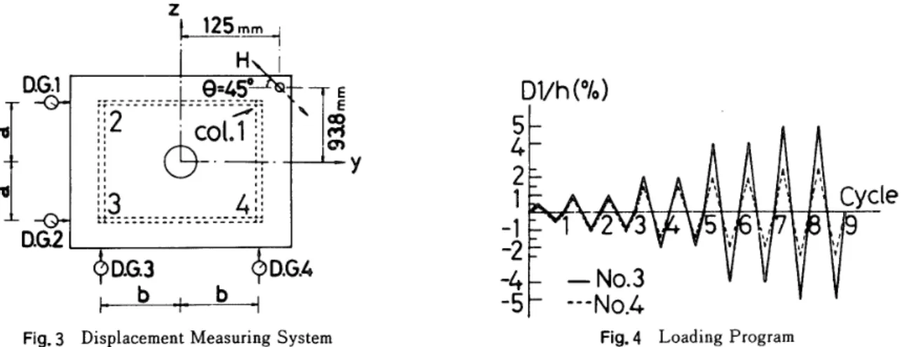
F]g.3
Displacement
Measuring
System
Fig.4
Loading
Prograrn
horizontal
load.
Another
set ofhut
gauge.
channelbeam
andloading
frame
is
prepared
onthe
other side ofthe
loading
device
(g)
for
the
reversedhorizontal
loading.
The
movements ofthe
roofplate
ofthe
specimen are measuredby
4
dial
gauges
as shownin
Fig.3,
which are set alongthe
beam
lines.
The
intensity
of
the
horizontal
load
is
computed
from
strains
measured
by
wirestrain
gauges
(m)
mounted onthe
flat
plate
portion
ofthe
hut
gauge
shownin
Fig.2(b).
2.3
TestResults
Figure
4
showsloading
programs
for
the
repeatedhorizontal
load
appliedto
specimensNo.
3
andNo.
4,
in
whichD1
denotes
the
dispiacement
data
obtainedby
the
dial
gauge
D.G.
1
in
Fig.3,
andih
denotes
the
columnheight
(=
10cm)
.
Direction
ofpositive
horizontal
load
is
indicated
by
a solid arrowin
Fig.3.
Horizontal
load
displacement
curves,displacement
path
atthe
center ofthe
roofplate,
and accumttiation ofthe
column axial strains are shownby
solidtines
in
Figs.
6
through
12.
In
the
figures,
H
denotes
the
horizontal
load,
andu.,,
u.
and
di,
denote
the
horizontal
di$placements
atthe
center ofthe
roofplate
in
y
and2
directions
andthe
rotationangle
of
the
roofplate
about x axis, respectively.The
values ofu.,,
u.,
andip,
are computedin
the
foLlowing
manner
from
the
displacement
data
Dl
through
D4
which are obtainedby
the
dial
gauges
D.G.
1
through
D.G.4,
respectively,In
view ofFig.3,
wehave
Dl=upa-(a-un)ipo""'"-"-"-"'""'"""""'-"''"""'-'""''"""""'''"""''--・---・・-・-・・(O
D2=use+(a+un)dio-''-'--""'"'''-H''""-"''-''-'"----'''"'-'-'-"'"''''""""''""'-'-'"'(2)
D3=umo-(b+usu)
¢
o-・・・--・"''・--''''・・-'''''・・''''"'・''''・'''''-''''''"'':"''''''-'''''''''-'''"''''''''''''・-・'・・'・・・-・・<3)D4=unt+{b-ust)
¢
o-・-・-・・・・・・・・・・・-・・-・・-・・-・・・・-・・・-・・-・・・-・・・-・・・--・・・・・・・-・・・-・・・・・・-・・-・・・・・・・--・・・・・・-・・-・・・・・・・・・(4)where "a"
denotes
half.
adistance
between
D,G,1
andD.G,2
(=
75
mrn), and "b"that
between
D.G.3
andD.G.4<=100
mm).The
value of ¢,is
first
given
by
an average oftwo
values:
the
oneis
obtainedfrom
Eqs.
(1)
and(2
),
andthe
other
from
Eqs.(3)
and(4
).
Thus,
ipo=l(D2-Dl)la+(D4-D3)lbl!4-・-・-・-・-・-・--・-・-・-・-・---・・--・--・----(5)
The
valuesof
use
and
u.
are
computedby
solvingtwo
simultaneous equations, which are obtainedby.
tidcling
Eqs.(1)
to
(2
),
andEqs,(3)
to
(4
),
asfollows:
use=KDI+D2)-dio(D3+D4}ll(1+
¢
:)IZ・・・・・・・・・・・・-・t・-・・・-・・・-・・・・・・・-・・・--・・--・・・-・・・・・・・・・・-・・・・-・・・・・・・-・-・・・・-・・・・・(6>
un=KD3+D4)+
¢
o(D1+D2)ll(1+¢
:)/2-'''''''''''''''-'''''''''''''''''''''''''''''''''''''''''''"'''-'''''''-'"''''<7)
In
the
equations above,the
value ofthe
clial
gauge
data
takes
positive
sign, whenthe
rod ofthe
dial
gauge
goes
out.
3.
Theoretical
Analysis
Twe
methods
are
applied
te
analysethe
elasto-plasticbehavior
of spaceframes
tested.
The
first
is
the
plastic
hinge
method2], and applied onlyto
the
frames
subjectedto
the
monotonichorizontal
load.
The
second methoddivides
the
columninto
3
portions
;
arigid
intermediate
portion
and
elasto-plastically
deformable
end
portionsiO].
Details
ofthe
numerical computationprocedure
aregiven
in
Refs.
2)
and10).
3.1
Analytical
Model
andAssumptions
Model
frame
analysed
is
the
one
usedin
the
test,
whichis
composed of4 columns of rectangttlar cross section,-10-NII-Electronic Library Service
Assumptions
are asfollows
:
the
roofis
completely rigidin
its
plane,
columnbases
arefixed,
noinitial
imperfections
exist,the
roofplate
does
not rotate about eithery
orz
axisin
Fig.3,
andthe
intensity
of axialforce
is
identical
and eonstantin
4
columns.These
assumptionsimply
that
only3
componentsof
defermation
arepossible
to
take
place
atthe
columntop;horizontal
translations
in
two
directions
andtorsional
apgle.In
addition,distributions
ofbiaxial
bending
moments andt6rsional
moment atongthe
longitudinal
axispf
the
cloumnbecome
antisymmetrical.Other
assumptions relatedto
the
evaluation ofthe
column stiffness aredescribed
ip
the
following
section.
3.2
Column
Stiffness
The
column stiffnessis
obtained,in
general;
by
solving a set of coupleddifferential
equations whichgovern
the
equilibrium of elasto-plastically'deformed column memb6r undeT combinedLoading.
However,
closed-form solution cannotbe
obtained,hence
the
column stiffnessis
evaluatedin
approximate mannerin
the
present
analysis
6f
two
kinds
by
assumingthat
the
differential
equations are not coupled,The
first
analysis employsthe
generalized
plastic
hinge
method,in
whjchthe
column stiffnessin
the
elastic Tangeis
assumedto
be
given
by
the
stability
functions
for
a member ofdoubly
symrnetrical cross section2), andthe
stiffness of ahinged
memberis
6btained
from'
the
yield
function
andthe
plastic
fiow
rule, asdescribed
in
Ref.
32).
As
to
the
yield
function
Y,
'
the
following
spheTicalfunction
is
employed:
Y=(NINo)t+(Mle11lfro)!+(My/Mge)l+(MxlMav)!=1・O'-'''''''''''''''-'''-''''''''''''''''''''-''''''''''-'''''''-'''(8)
where
N,
M.,
M.
andM.
= axialforce,
torsional
moment, andbending
moments abottty
and z axes,respectiv.ely, and
the
subscript
odesignates
the
full
plastic
value.The
celumn
stiffnessin
the
second method ofAnalysis
is
gbtained
based
entwo
assumptionsiO):
i
)
elasto-plastic
flexural
defo[mation
takes
place
onlyin
the
endportions
ofthe
column whoselength
is
116
ofthe
columnheight,
and
otherportion
is
completely rigid;ii) asto
the
torsion,
the
columnbehaves
in
the
perfectly
elasticmanner.
3.3
Numerical
Computation
Input
data
for
the
analysisof
the
frames
tested
are
those
listed
in
Tables1
and
2.
Hysteretic
stress・strain
retation used
in
the
analysis
by
the
method assumingthe
deformable
portions
at column endsis
abilinear
type
as shownin
Fig.5.
The
value ofu
is
taken
equalto
8
×10-3
for
frames
subjectedto
the
repeatedhorizontal
load,
which
approximates
the
stress-strain
curves obtainedby
coupontests,
whileit
is
taken
equalto
10m4
for
frames
under
the
monotonicloading,
sincethe
effect of strainhardening
hardly
appearsin
the
tests
ofthose
fTames.
In
the
analysisby
the
plastic
hinge
method,the
endforce
vector at aplastic
hinge
is
assymedto
remain onthe・
tangent
plane
to
the
yield
surface,hence
the
endferce
vector extendsbeyond
the
initial
yietd
surface,Y=1.0,
RefeJence
32)
showsa
technique
to
reducethe
force
vector atthe
pastic
hinge
withoutdisturbing
the
ovetall equilibrillm condition.In
the
present
analysis,
the
columnstiffness
of
the
hinged
columnis
modified moiesimply
by
ihtroducing
anewtangent
plane
wheneverthe
force
vector atthe
plastic
hinge
reaches anewyield
surface,which
is
predefined
asY=
'
1.
0,
1.
05,
1.
10"'
withan
interval
ofO.
05.
This
treatmenthas
been
shown
in
Ref.
33).
Nume'rical
results ofthe
values ofY
ofthe
first
hinge
atthe
time
ofthe
last
hinge
forming
are'as
follows:Y=1.051
in
spe6imen
No.1,
and =1.075in
No.2.
Ih
the
analysis
by
the
method assumingthe
deformable
portions
at'
colurnn ends,
iterative
procedure
is
required, of whichdetails
aredescribed
in
'4.
Discussion
and
Conclusions
4,1
Discussionon
Test
Results
Results
of
Mbnotonic
Loading
71rsts
Test
resultsof
specimens
No.1
(N=O.
3
IVI)
andNo.
Z
(N=O.
5
N.),
are shownby
solidlines
in
intensity
ofthe
verticalload
appear
clearlyon
the
reduction ofthe
6
6yJEE
pEtt
.6y
Fig5
the
column stiffnessdepends
onthe
deformation
as usualin
ageneral
nonlinearproblem,
Ref,
10),
E
Idealized
Stress-Strain
Relation
and
thus
an
subjected
to
the
monot,onich6rizontal
load,
Figs.6
and7,
respectiv6Iy.Effects
ofthe
maximum
load
carrying capacityand
the
Architectural Institute of Japan
ArchitecturalInstitute ofJapanH(kg)
80
60
40
20
"
tj7
tlt
"t
ft t .' t NM -tl tIi
itl .7,vv''-t'-H(kg)
80・kt
601l
40!
120
o
2
4
6
-2
Uzo(rn
rn)Uyo
(mm)
(b)
Fig.6
Results
ofTest
andAnatysis
:
H(kg)
80
60
40
20
(a)
-'1s-NX
v, NX"
Ns
sc
N ".
N.
1
Ns,,
L1':'1 UIO(MM):
X
5
s.L -'hN ,,114
"X
3
X2
NXx
1
H(kg)
H(kg)
pt.
,Rl60f'x..
t'l60
I N 1 JSS I40:
Nx.Sslk./L4o
xF
N.
i
20
20
XNl
ttO,2
4-2
O
Uzo(mm)
Uyo(mm)
(a>
(b}
Fig.
7
Results
ofTest
andAnalysis
deformation
capacity.The
negative slope ofthe
load-dis
becomes
steeper
asthe
verticalload
becomes
larger.
It
is
in
Figs.6(d}
and7(d)
that
the
value of u.keeps
'
displacement
range.The
value ofu.,
which correspondsthe
vatue ofu.
at a certainlevel
ofthe
horizontal
load
H
:
z
axis, andthe
value ofun
further
increases.
The
markv
in
Fig,
6
indicates
the
point
at whichthe
does
net
appear
in
the
resultsef
specimen
No.2
shown'
Fig,7.
In
the
case
of
frarnes
withslender
columns
andlor
subjected
to
the
large
verticalload,
the
failure
due
to
the
instability
effect
takes
place
befo!e
the
strain
reaches
into
the
strain
hardening
range.Figure
8
showsthe
centroidal strainsthi
and Eosatthe
bases
of colttmns1
and3
shownin
Fig.
3,
which aTethe
closest andthe
farthest
to
the
hoTizolltal
lead
point,
respectively.
Although
the
extremefiber
strainsbecome
yeTylarge,
the
centroidal strains remain rather small, especiallyin
the
case of Eos.Results
of
(
lyclic
Loading
7lasts
Test
results of specimensNo.
3
{N=O.
3
IVL,)
ancl
No.
4
(N=O.
5
IVI)
which are subjectedto
the
repeatedhorizontal
load
are shownby
solidlines
in
Figs.
g
and
10,
respectively.The
load-displacement
relationsplacement
observed
lncreaslngto
the
weakth
largest
ln
O
O
O.04
-3
-2
-i
Uyo(rnm)
%
Crad.)
{c)
{d)
Specimen
No.
1
(n=O,
3}
Uzo<mm>
H(kg)
pt60
'k,i40
X
x
20
X
t'
O
O04
tg
(rad.)
Uyo
<Mm)
(c)
{d}
Specirnen
No,
Z
(n=O.
5)
curve after
the
maximum capacityis
attainedin
the
diagrams
efdisplacement
path
shown'
while usc shows slow
progress
in
the
large
axis
bending
ofthe
column,is
largeT
than
is
situatien causeslarger
PA
momentabout
y
than
strain exceeds
the
value of E.,in
Table
2.
This
H(kg)
80
60
40
20
ls
NNxNxN
4
qtt13tsls"2,"s1
-2-1
No.
1
N
Neo3
N.
N
Eel
kH(kg)
60
tx40
X
N
20
X
eo3
o
E]oi(Fig.8
No
N
.2eol
o
O.1xl
o'i
)
Centroidal
Strain
O.05Eoi(x1o'i)
NII-Electronic Library Service
of
specimen
No.
3
shownin
Figs.
9(a),
(b)
and<c)
indicate
the
following
characteristics:
hysteresis
loop
enlargesas
the
number ofloading
cyclesincreases;the
shape ofloops
is
a stable spindletype
and
symmetrical
about
the
origin.
On
the
otherhand,
in
the
case of specimenNo.4
subjectedto
the
larger
verticalload,
the
loop
drifts
awayto
the
negative
loading
side
from
the
origin,
as
observed
in
Figs.
10(a),
(b)
and
(c),
although
the
values ofD1
used asa
monitorfor
the
loadipg
are controlledto
・the
prescribed
values atthe
turning
points,
as
shown
in
Fig.
10(d).
In
the
case of
the
frame
with slender columns underthe
relativelylarge
verticalload,
it
maybe
saidthai
the
displacements
'
accumulate
in
onedirection
althoughdisplacement
at a specificpoint
is
controlled accordingto
the.
prescribed.
program,
which makesthe
frame
gradually
unstable andleads
it
to
the
faiiure
state,Test
ofspecimen
No.
4
waslini$hed
before
the
planned
number ofloading
cycles were applied.Figures9(d)
and10(e)
showthe
relationsbetween
u.
andu..
In
the'
case of specimenNo.3,
the
displacement
path
stays on a nearlyidentical
line,
whilethe
drift
ofloops
is
observedin
the
displacement
path
ofspecimen
No.4.
Strains
atthe
centroid of column1,
E,,, areplotted
in
Figs.9(e)
and10(f).
It
is
clearly seenthat
e,,of
specimenNo.4
accumulates withincreasing
cycles,but
the
value of e,,stays abouto,
s
%
in
the
case of specimenNo.
3.
4,2
Comparison
between
Results
ofTests
andAnalysis
Results
of
analysis
by
the
plastic
hinge
method are shownby
dashed
lines
with circles, andthose
by
the
method which assumes
the
deformable
portions
at column ends are shewnby'dashed
lines
in
some ofFigs.
6
through
10.
Circles
in
the
former
indicate
the
formation
ofthe
plastic
higes,
whichform
in
the
order of cloumns1,
,4,
2
and3
in
both
specimens underthe
monotonichorizontal
loading.
Comparisons
between
the
results oftest
and analysisfor
specimens subjectedto
the
repeat.edhorizontal
loading
are madefor
several selectedloops
as shownin
Figs,11
and12,
in
orderto
avoidthe
confusion.'
'
The
analysisby
the
plastic
hinge
method wellgrasps
the
overalibehavior
ofthe
spacefra'mes
subjectedto
the
Htk
x,
"ll
MM'li,
Li-lsil-l!YSIIg
'RIA,,
it,
ll dL"r 11 [ (.UV.e}'
[gt
kisxN
//tt
-4L
・::,
(a)
(b)
(c)
{d)
Ce)
'
Fig.9
ResuLts
efTest
andAnalysis
:
Specimen
No.
3
(n=O.3)
'
Htkq)
HC"g) H{kg)'
HcLg)
Un{mm.)I
ii
・,
I
i・
z
'
,,
+f
Yr,
'
:,
s,
,,.
(a)
(b)
(c)
(d)
(e>
(f)
Fig
10
Results
ofTest
a.ndAnalysis
:
SpecimeR
No.
4
(n=O.
5)
H(kg}20[rtt80lLO
.aL/$(raa.
ve'
`-1ro
'
-13-Architectural Institute of Japan
ArchitecturalInstitute of Japan,
"tk9)Htltg)
1Jt1''rdH(kg)ltan;
X.tt:i80r
".t d//'1 1 It1il
lt
1/:':1 Hfkg)'
O,02
I
i
'%i
,rtsost.ssssr'-lelitd+NtMs' dl d 1 , ,:
" 1ifr,1i2:rld3um{mm
t+d g:i-co: NJdv""l4J,
-so1'
H[kg}-TtoL
(a)
{b)
(c)
Fig.11
Comparison
ofHysteresis
Loop$
1
Specirnen
No.3
(n=O.3),
5th
and9th
Cycles
(a)Fig.12
80
11
ti
t 1 , IL ll 1111-L1
11 lb
i
II-cai:
L:.soli
" 1:1:,
401;
, 'l uyoICmm)
;
t J t ttr'rt{b)
Hkg)eof,;1fi,co:l/11di1ddt-1Il:'ooz1o.pa
::$::Crad,)
r1,,to,1,'''1d,1-soComparison
efHysteresis
Loops
:
No,4
(n=O.
5),
3rd
and6th
Cycles
(c)Speclmen
monotonic
horizontal
load,
except
that
it
gives
felativelyhigher
maximum
load
carrying capacitythan
that
obtained
in
the
test.
This
is
simply
because
the
assumedyield
condition,
Eq,(8),
is
an appioximationto
the
true
yield
surfacefrom
the
outside, andit
overestimates
the
stress
state
atyielding.
In
the
analysisby
the
method assumingthe
deformable
portions
at column ends,the
approximatesolution
for
th
columntop
displacement,
based
onthe
length
ofthe
defoTmable
portion
equalto
hl6,
becomes
larger
than
the
exact solution, once
the
yielding
startsin
the
column.This
resu}tsin
the
larger
PA
moment and consequentlyin
the
low
estimate
ofthe
maximumload
carrying
capacity.However,
the
analysisby
this
method wetlgrasps
the
following
characteristics
observedin
the
tests
:
i)
ceasing
of
increase
in
u.
in
the
large
deformation
rangein
specimens subjected
to
the
monotonichorizontal
load
(Figs.6(cl)
and7(d));
ii)
small values of E,, and eo!(Fig.8);iiO
gradual
enlargementof
hysteresis
Ioops
(Figs.
11(a),
(b)
and(c))
andlinear
relationbetween
u.
and u. of specimen
No.3
(Fig.9(d))
;and
iv)
drifts
of
hysteresis
loops
(Figs.12{a),
(b)
and(c))
and accumulation ofthe
strain E,,of specimenNo.4
(Fig.
10(f)).
Phenomena,
similarto
those
obseJvedin
the
present
test,
e.g.,the
enlargingloops
andthe
axial strains which may or may not convergedepending
onthe
intensity
ofthe
axialforce,
have
been
observedin
the
in-plane
behavior
of members andframesM)・35).
The
divergent
behavier
ef specimenNo.4
maybe
due
to
the
non-symmetrical
deflection
of
beam-colttmns
whichhas
been
investigated
in
Ref.
36).
These
characteristics
mustbe
relatedto
the
column
slenderness,the
verticalload
ratio andthe
displacement
amplitllde,but
the
derivation
ofthe
quantitative
relationis
left
to
the
future
theoretical
investigation.
4.3
Conclusions
1.
The
frame
specimentested
has
the
strong and weak axes asto
the
resistance againstthe
horizontal
load,
and
they
arepararell
to
those
ofindividual
column.In
such aframe,
it
has
been
already
ebserved elsewheTe5)that
the
displacement
correspondingto
bending
aboutthe
strong(2)
axis,u.,
cea$esto
progress
in
the
large
displacement
range,if
the
monotonichorizontal
load
passing
throuth
the
centroid with aninclined
angleto
the
principal
axis ofthe
frame
is
applied,but
notin
the
case
of
the
cyclic
loading.
The
present
test
showsthat
sucha
phenomenon
also occursin
the
case ofthe
horizontal
loading
with alarge
eccentricity, regardless ofthe
loading
type;monotonic
or cyclic,The
reasonis
clearly explained:
the
increment
ofu.
is
accelerateddue
to
the
PA
moment whichbecomes
largei
abouty
than
z
axis,2.
The
specimen subjectedto
the
cyclichorizontal
load
withthe
verticalload
ratio equalto
O,
3
show
spindle
shaped
load-displacernent
hysteresis
loops
which are stable, symmetrical aboutthe
origin, and enlarge withthe
increase
in
the
loading
cycle, eyenthough
the
horizontal
load
eccentricityis
faifly
large.
On
the
otherhand,
in
the
case ofthe
specimenwith
the
verticalload
[atio equalto
O.
5,
eventhough
the
loading
is
controlled sothat
NII-Electronic Library Service
the
values of a specificdisplacement
atturning
points
become
prescribed
values,hysteresis
loops
for
othergeneral
displacements
drift
away
from
the
origin, which resultsin
the
instability
failure
with excessivedisplacements'.
3.
It
is
observedin
the
tests
that
the
centroidal stiains at columnbases
remain rather smatlin
the
frames
subjected
to
monotonighgrizontal
loading.
As
to
the
frgmes
subjectedto
the
cyclicIoading,
the
centroidal strainin
the
column closestto
the
load
point
convergesto
a certain valuein
specimenNo,
3
withthe
vert'icalload
ratio equalto
O.3,
whileplastic
compressive
strain accumulates with'theincrease
in
the
loading
cyclein
specimenNo.4
withthe
verticatload
ratioequal
to
O.
5.
4.
The
present
tests
confirmthe
convergence anddivergence
phenomena
stated ab6veto
occurin
the
spaceframe
behavior,
whichhave
been
obseryedin
the
tests
ofplane
frames
and
members34)n36).The
clear-cut
boundary
between
the
convergence andthe
divergence
may exist, and.maybe
relatedto
severalprincipal
parameters
such as column slenderness, verticalload
ratio anddisplacement
amplitude,Derivation
ofquantitative
relationsis
left
to
the
future
work..
'
'
s.
Two
methods of analysis emloyedin
the
present
work areboth
simple, easyto
apply,and
satisfactoryto
gra$p
the
overall restoringforce
characteristics of spaceframes,
althoughthey
have
alittle
deficiency
such asin
'
'
evaluating
the
load
carrying
capacity.
'
Acknozvledgments
The
authors wishto
expresstheir
appreciationto
Mrs.
Fumiko
Saito,
formerly
a
gradu.ate
student of
Kyoto
University,
for
her
assistancein
carryingthe
experiments andprocessing
the
data.
The
authorsare also
gTateful
to
Di.
Yasuhiro
Uchida,
an assistant ofMie
University,
for
his
help
in
the
numericalcomputatlon.
Reterences
.
.
'
1)
Chen,
W.
F.
andAtsuta,
T.
:
Theery
ofBeam-Columns,
Vol.2
:
Space
Behavior
andDesign,
McG{aw
HiLI
{]977)'.
2)
Merino.
S.
andLu,
L.W.
:
Fritz
EngineeTing
LaberatoTy
Report
Ne.331.1,
Lehigh
Univ.
(197o.IQ)'.
3)
Wakabayashi,
M.,
Morino,
S.,
Nishimura,
F.,
andHetaka,
S.
:
Abstracts,
Annual
Meeting'of
AIJ,
p.]osg
(1973.10).
4)
Wakabayashi,
M.,
Nakamura,
T.
andInoue,
A.
:
Annuals,
DisasterPrevention
Research
Institute,
Kyoto
Univ.,
p.105
(1976.4}.
s)
Fujimoto,
M.
andOkada,
H.
:Trans.
AIJ,
No.244,
p.41
(1976,6),
No.245,
p.75
(1976.7),
No,246,
p,
43
(1976.8}.
6}
IgarashL,
S.,
Tsujioka,
S.,
Uno,
N,,
et al.IAbstracts,,Annual
Meeting
ofAIJ,
p.1137
(1976.10),
p,l139
(1976.10),
p.1377
(1977.]O),
p.1395
{1978.9).
7)
Kojima,
H.,
Hirao,
K,
andYano,
T.:Proc.
・JSCE,
No.240,
p.ll
(1977.'8).
s)
Okamote,
H..
:
Abstracts,
Annual
Meeting
ofAIJ,
p.
I419
(1978.
9)1
g)
Igarashi,
S.,
Tsujioka,
S.
andIkoma.
Y.
:
Abstracts.
Annual
Meeting
ofAIJ,p.114t
(1978.9},
p.815
(1979.9},
p.995
(1980.9),
'
lo)
Matsui,
C.,
Morino,
S.
andUchida,
Y.
:
Abstracts,
Annual
Meeting
ofAIJ,
p.1179
(l980,9).
Trans.
AIJ,
No.319,
p.l
{l982.9),
'
11)
Kadokawa,
N.
andNishikawa,
H.
:
Abstracts,
Annual
Meeting
ofAIJ,
p.
759
{1981.9),
12)
Suzuki,
T.
andTakeda,
T.
:
Abstracts,
Anntial
Meeting
ofAIJ,
p.761
(1981.9),
p.763
(1981.9}.
'
13}
Shugyq
M.
:
Abstracts,
Annual
Meetlng
ofAIJ,
p.
19]9
(1981.9).
14)
Yamazaki,
Y.:Trans.
AIJ.'No.310,
p.61
(1981J12}.
'
ls)
Ishikawa,
N.,
Ohno,
T.
andOkamoto,
K.:Proc.
JSCE,
No.279,
p.45
(1978.11).
16)
Zlmmerli,
B.
andThurlimann,
B.:Proc,
ASCE,
J,
Str,
Div.,Vol.105,
No.ST3,
p.481
(1979.3)'.
17)
Kimuia,
M.
andNanba,
H,
:
AbstTacts,
Annual
Meeting
ofAIJ,
p.
1349
(1980.9),
p,
l9Z3
(1981.9),
p.
1925
(1981,
9).
"ls)
Fujimoto,
M.
andMatsumoto,
Y.
:
Trans.
AIJ,
No.186,
p.27
(1971.8),
No.187,
p.51
(1971.9).
Ig)
Wakabayashi,
M.,
Okamoto,
H.
andUra,
H.
:Abstracts,
Annual
Meeting
ofAIJ,
p.1361
(1972.10).
2o)
Suzuki,
T.,
Tarnamatsu,
K.
andKubodera,
I.
:Trans.
AIJ,
Ne.
265,
p.
33
(1978.3).
21)
Igarashi.
S.,
Tsujioka,
S,
et al,:
Abstracts,
Annual
Meeting
ofAIJ,
p.1351
(1980.9},
p,1931
(1981.9}.
p.1933
'
(1981.9).
'・
22}
Fujisawa,
K.,
Terada,
T.
andKimura,
T.
:
Abstracts,
Annual.
Meeting
ofAIJ,p.I913
(1981.9).
23)
Fujimoto,
M,
andMidorikawa,
M.
:Trans.
AIJ,
No.282,
p.9
(1979.8),
No.298,
p.19
(1980.12).
24}
Igarashi,
S,,
Tsujioka,
S.
andNomura,
Y.,
et aL:
Abstracts,
AnnuaL
Meeting
ofAIJ.
p.1379
(l977.IO),
p.1393