B BB00035006-101 LP553A-S35 2807
UA80×9BESM-S35E
技術資料/
Technical Drawings
/技术资料
中 文 版
ENGLISH
日 本 語
この取扱説明書は「日本語版」「英語版」「中文版」「技術資料」から構成されています。 This operation manual is composed of the Japanese version, English version, Chinese version, and Technical Drawings.
日本語版 中文版 本使用手册包含日文版本英文版本中文版本技术资料。 日本語版 中文版 技术资料 English version 技術資料 Technical Drawings 技术资料 English version
日本語版
JAPANESE VERSION
技術資料/
Technical Drawings
/技术资料
中 文 版
ENGLISH
日 本 語
SM-21-T2/R1 i
-目
次
■安全にお使いいただくために・・・・・・・・・・・・・・・・・・・・・・・・・・・・・・・・・・・・・・・・・・・ⅱ
■ご使用の前に・・・・・・・・・・・・・・・・・・・・・・・・・・・・・・・・・・・・・・・・・・・・・・・・・・・・・・・・・ⅳ
・カメラへ取り付ける前に・・・・・・・・・・・・・・・・・・・・・・・・・・・・・・・・・・・・・・・・・・・ⅳ
・レンズサポータご使用時の注意・・・・・・・・・・・・・・・・・・・・・・・・・・・・・・・・・・・・・ⅳ
・乾燥剤の収納・・・・・・・・・・・・・・・・・・・・・・・・・・・・・・・・・・・・・・・・・・・・・・・・・・・・・ⅳ
・カメラの選択・・・・・・・・・・・・・・・・・・・・・・・・・・・・・・・・・・・・・・・・・・・・・・・・・・・・・ⅴ
・カメラモードの設定・・・・・・・・・・・・・・・・・・・・・・・・・・・・・・・・・・・・・・・・・・・・・・・ⅵ
■概説・・・・・・・・・・・・・・・・・・・・・・・・・・・・・・・・・・・・・・・・・・・・・・・・・・・・・・・・・・・・・・・・・ 1
■商品構成・・・・・・・・・・・・・・・・・・・・・・・・・・・・・・・・・・・・・・・・・・・・・・・・・・・・・・・・・・・・・ 1
■仕様・・・・・・・・・・・・・・・・・・・・・・・・・・・・・・・・・・・・・・・・・・・・・・・・・・・・・・・・・・・・・・・・・ 2
■各部の名称と機能・・・・・・・・・・・・・・・・・・・・・・・・・・・・・・・・・・・・・・・・・・・・・・・・・・・・・ 3
■取付方法・・・・・・・・・・・・・・・・・・・・・・・・・・・・・・・・・・・・・・・・・・・・・・・・・・・・・・・・・・・・・ 5
■フランジバックの調整・・・・・・・・・・・・・・・・・・・・・・・・・・・・・・・・・・・・・・・・・・・・・・・・・ 6
■アイリスアンプの調整・・・・・・・・・・・・・・・・・・・・・・・・・・・・・・・・・・・・・・・・・・・・・・・・・10
■画角変化補正機能について・・・・・・・・・・・・・・・・・・・・・・・・・・・・・・・・・・・・・・・・・・・・・11
■エンコーダ出力信号仕様・・・・・・・・・・・・・・・・・・・・・・・・・・・・・・・・・・・・・・・・・・・・・・・12
4■
◇
◇
◇
◇
◇
4 5■
◇
3
◇
◇
◇
フォーカス操作・・・・・・・・・・・・・・・・・・・・・・・・・・・・・・・・・・・・・・・・・・・・・・・・・・・・ 8
ズーム操作・・・・・・・・・・・・・・・・・・・・・・・・・・・・・・・・・・・・・・・・・・・・・・・・・・・・・・・・ 8
アイリス操作・・・・・・・・・・・・・・・・・・・・・・・・・・・・・・・・・・・・・・・・・・・・・・・・・・・・・・ 8
エクステンダ切替操作・・・・・・・・・・・・・・・・・・・・・・・・・・・・・・・・・・・・・・・・・・・・・・ 9
マクロ操作・・・・・・・・・・・・・・・・・・・・・・・・・・・・・・・・・・・・・・・・・・・・・・・・・・・・・・・・ 9
操作方法・・・・・・・・・・・・・・・・・・・・・・・・・・・・・・・・・・・・・・・・・・・・・・・・・・・・・・・・・・・・・ 8
日常の整備・・・・・・・・・・・・・・・・・・・・・・・・・・・・・・・・・・・・・・・・・・・・・・・・・・・・・・・・13
水分の除去・・・・・・・・・・・・・・・・・・・・・・・・・・・・・・・・・・・・・・・・・・・・・・・・・・・・・・・・13
レンズの保管・・・・・・・・・・・・・・・・・・・・・・・・・・・・・・・・・・・・・・・・・・・・・・・・・・・・・・13
点検・・・・・・・・・・・・・・・・・・・・・・・・・・・・・・・・・・・・・・・・・・・・・・・・・・・・・・・・・・・・・・13
保守・点検・・・・・・・・・・・・・・・・・・・・・・・・・・・・・・・・・・・・・・・・・・・・・・・・・・・・・・・・・・・13
1 2 3 1 2安全にお使いいただくために E1462/R4 ii
-警告
誤った取り扱いをしたときに、人が死亡または重傷を負う可能性が
想定される内容を示します。
注意
誤った取り扱いをしたときに、人が傷害を負ったり、物的損害の発
生が想定される内容を示します。
してはいけない「禁止」の内容を示します。
安全にお使いいただくために
ここでは、製品を安全に正しくご使用いただくために、重要な注意事項を説明しています。 必ずご使用前に読み、記載内容に従って正しくご使用ください。 文章中の表示は次のことを表しています。 レンズには、既定の付属品以外の物を取り付けな いでください。また、レンズの上には物を載せない でください。操作時に落下して、重大な事故の原 因となります。 太陽や高輝度の光源をレンズを通して見な いください。目に障害を負う原因となります。 ◆ 取り付け・締め付けは確実に行ってください。高所使用時の落下は重大な事故の原因となります。警 告
レンズの内部に水が入らないようにしてください。 火災や感電の原因となります。 万一水が入ったときは、すぐにレンズに供給して いる電源を切ってください。 レンズをカメラに取り付けた状態で、カメラを下方 に45°以上傾けないでください。レンズがカメラより 落下して、重大な事故の原因となります。上記の 姿勢で撮影をする必要がある場合には、落下防 止のために処置をレンズに施してください。 ◆ カメラを操作するときは、カメラの動作範囲内に障害物がないか、操作の前に確認してください。 レンズが障害物に強い衝撃で当たると、カメラより落下して重大な事故の原因となります。安全にお使いいただくために E1462/R4 iii
-△
注 意
◆ 運搬中の落下は、けがの原因となります。落とさないように注意してください。 ◆ レンズに供給する電源は、各機器が正しく接続されていることを確認した後に入れてください。 ◆ ケーブルを着脱するときは、必ずコネクタ部分を持ってください。ケーブルを傷つけると、火災や感電の原因と なります。 ◆ 発煙・異常音・異臭・異物混入などの異常のときは、すぐにレンズに供給している電源を切ってからレンズを カメラから取り外してください。その後、購入先販売店にご連絡ください。 ◆ 分解・改造を行わないでください。製品の機能を損ねたり、感電の原因となります。一般的な注意
◆ レンズおよびその付属品は精密機械です。決して強い衝撃を与えないでください。 レンズマウントのフランジ面より後方にレンズ部分が突き出ているレンズの場合、取り付け・取り外しの際、レン ズ部分に衝撃を与えないよう十分に注意してください。 ◆ レンズを寒いところから急に、気温と湿気が高いところに持ち込むと、レンズが曇ることがあります。 上記のような環境へレンズを持ち込むときは、前もってレンズを使用環境温度へ適合させるなどの曇り対策を 講じてください。 ◆ カメラを操作するときは、レンズの前部に衝撃を与えないよう十分に注意してください。 ◆ カメラを使用しないときは、レンズにはレンズキャップを取り付けてください。 ◆ 駆動伝達部がある付属品を取り付ける場合、かみ合い部分の形状に異常はないか、異物の付着はないか 十分に点検してください。異物があるときは確実に取り除いてください。形状に異常があるときは、購入先販 売店にご相談ください。 ◆ 濃霧・降雨・降雪などの環境で使用するときは、覆いをするなどの対策をして、製品に水分がかからないように してください。 ◆ 輸送時のレンズへの衝撃を最小限にするために、レンズをカメラから取り外す前に、ズームはワイド端に、 フ ォーカスは無限遠側一杯の位置になるように設定してください。ご使用の前に NT66-1 ⅳ -■ カメラへ取り付ける前に このレンズを、ソニー製スタジオ用カメラ(HDC-2000等)、またはソニー製大型レンズアダプタ(HDLA-1500等) に取り付けるときは、レンズのバヨネットマウントにあるピンを外し、マウント枠にあるねじ穴に取り付けてくださ い。他のカメラに取り付ける場合は、ピンを元の位置に戻してください。 ねじ穴 ピン ■ レンズサポータご使用時の注意 このレンズをフジノンレンズサポータ(ELH-*)に取り付けて使用する際には、 パワーソース用コネクタ(“各部 の名称と機能”参照)からレンズ側に電源を供給して下さい。 電源を供給しない場合、 正常動作しないことが あります。
ご 使 用 の 前 に
■ 本レンズは、レンズ内部の曇りの原因となる湿気を除去する目的で乾燥剤を収納する機構となっています。工場 出荷時には、あらかじめレンズ内に保存用の乾燥剤を収納していますので、ご使用の前に以下の要領で新しい 乾燥剤と交換してください。 収納箱から乾燥剤を取り出します。乾燥剤は 5 袋入りとなっていますが、このうち 2 袋を使用します。残りは 次の交換の際に使用してください。 レンズ本体の両側にあるカバー取付つまみをゆるめます。カバーを前方に引いて外してください。 乾燥剤収納部の 4 本のねじを外し、ふたを取ります。 収納されている乾燥剤を取り出します。 新しい乾燥剤 2 つをそれぞれ 2 つ折りにし、収納部に入れます。 ふたを取り付け直し、カバーを元に戻します。 注 1. 乾燥剤の収納は、ホコリのない場所で行ってください。 注 2. 湿度の高い地域では、半年に一回程度の交換をお勧めします。乾燥剤がゼリー状になると交換の時期です。 乾燥剤の収納 乾燥剤収納部 新しい乾燥剤 保存用乾燥剤 a. b. c. d. e. f.ご使用の前に NT58-2 v -■カメラの選択 アクセサリのインターカム選択スイッチは、カメラの機種により動作が異なります。レンズ内の A-ボード上に、カメラを選択 するディップスイッチ (S710-7) がありますので、ご使用上不都合な場合には、このスイッチを切り替えてください。 なお、工場出荷時には、TYPE 1 に設定してあります。参考までに、下図に内部の接続を示します。 注. TYPE 2 のカメラの場合、カメラ側のインターカム選択スイッチは、『PD』に設定してください。 『ENG』に設定すると、ズームレートデマンドユニットから『PD』が選択できません。
A-ボード
S710 ディップスイッチ (S710-7) の設定 OFF: Camera Type 1ON: Camera Type 2
1 2 3 4 5 6 7 8 O N
Ⅰ. TYPE 1 CAMERA: BVP-270 series (NTSC) and BVP-370 series (NTSC)
INCOM 1 SW ENG
PD ACCESSORY
(EX. ERD-5A-D01/ERD-5A-D11) LENS
Ⅱ. TYPE 2 CAMERA: BVP-370 series (PAL)
INCOM SETTING LINE ENG
PD ACCESSORY (EX. ERD-5A-D01/ERD-5A-D11) LENS INCOM 2 SW CAMERA INCOM (1) SW CAMERA
A-ボード
NT58-2 vi -■カメラモードの設定 使用するカメラが、シリアル通信に対応していない場合には、レンズの通信モード(カメラモード)をOFFに設定し てください。 設定方法 レンズカバーを外すと、(レンズ前玉側から見て)レンズの右側面にAボードがあります。Aボード上にスイッチ S703がありますので、このスイッチを『OFF』にします。 注. 工場出荷時、S703はONに設定されています。 S703
A-ボード
最初に、レンズカバーを取り外してください。 レンズ本体の両側にあるカバー取付つまみをゆるめ、カバーを前方に引くと外れます。LP550-S/R0 1 -フジノン TV レンズUA80×9シリーズは、 2/3″フォーマット 4K UHD TV用に開発された、高性能ズームレンズ です。 ズーム比は、80倍という超高倍率。さらに1.2倍および2倍のエクステンダを内蔵し、最大焦点距離1440mmの超望 遠レンズとなっ て い ま す 。 明 る さ は 、 超 高 倍 率 化 に も か か わ ら ず F1.7(ワイド側)。このような優れた特長を持ち ながら小型軽量化を実現し、屋外用に最適なレンズとなっています。 画面上の像ブレを低減させる防振機構が内蔵されています。レンズ内部の振動検出センサや補正光学系などの 働きにより、風の強い屋外や足場が不安定な場所においても像ブレの少ない、安定した映像を撮影することがで きます。
このレンズは 32 ビット RISC (Reduced Instruction Set Computer) CPU を搭載したデジタル仕様となっていま す。RISC CPU を使用して信号をデジタル処理することにより、レンズの各部を高い精度で制御することが可能となり ました。また、コンピュータと通信するためのインターフェイスを備えていますので、コンピュータを使用して外部から レンズを制御することもできます。 ■標準構成品
概 説
商 品 構 成
1.レンズ本体・・・・・・・・・・・・・・・・・・・・・・・・・・・・・・・・・・・・・・・・・・・・・・・・・・・・・・・・・・・・・・・・・・・・・・ 1 ・前レンズキャップ・・・・・・・・・・・・・・・・・・・・・・・・・・・・・・・・・・・・・・・・・・・・・・・・・・・・・・・・・・・・・・ 1 ・後レンズキャップ・・・・・・・・・・・・・・・・・・・・・・・・・・・・・・・・・・・・・・・・・・・・・・・・・・・・・・・・・・・・・・ 1 2.清掃用具・・・・・・・・・・・・・・・・・・・・・・・・・・・・・・・・・・・・・・・・・・・・・・・・・・・・・・・・・・・・・・・・・・・・・・・・ 1LP550A-S35/R0 2
-LENS
項目
UA80×9BESM-S35E
適用カメラ 2/3” フォーマットカラーカメラ (プリズム型分解光学系) アスペクト比 16 : 9 画面寸法 9.59 × 5.39 mm (φ11.0 mm) 焦点距離 9.0~ 720 mm <10.8 ~ 864 mm> *1 [18.0 ~ 1440 mm] *2 ズーム比 80× (F No.) 最大口径時 F値 F1.7 (9.0~350 mm)~F3.5 (720 mm) <F2.0~F4.2>*1 [F3.4 ~ F7.0] *2 絞り範囲 F1.7 ~ F16、クローズ フランジバック (in Air) 至近距離 (前玉より) Fig. 1 参照 3.7 m (マクロ操作時: 0.3 m) 画 角 水平 / Hor. 垂直 / Ver. 対角 / Diag. 56゜06’~ 0゜46’ 33゜20’~ 0゜26’ 62゜52’~ 0゜53’ at Wide End 至近時被写体範囲 at Tele End 3501×1968 mm 46× 26 mm アイリス操作 サーボ ズーム操作 サーボ (最小作動時間: 約 1 秒 *3) またはマニュアル フォーカス操作 サーボ (最小作動時間: 約 0.8 秒) またはマニュアル 防振機構部 補正方向 対応周波数 補正量 垂直+水平または垂直のみ 3~10Hz 画面垂直方向で40% (エクステンダ非使用時、テレ端) マウント Fig. 1 参照 (at 12V DC) 消費電力 9.6 W (静止時) 27 W (最 大) 質 量 23.5 kg (約) *1 < > 内の各数字は、エクステンダ (1.2倍) を使用した時の数値を表します。 *3 ズーム用ハイスピードモジュールを使用しますと、最小作動時間は約0.6秒になります。仕 様
チルト操作範囲 ±45° <47゜53’~ 0゜38’>*1 <28゜01’~ 0゜21’> <53゜59’~ 0゜44’> <3009×1692 mm>*1 < 39× 22 mm> *2 [ ] 内の各数字は、エクステンダ (2倍) を使用した時の数値を表します。 [1816×1021 mm]*2 [ 23× 13 mm] [29゜50’~ 0゜23’]*2 [17゜02’~ 0゜13’] [33゜59’~ 0゜26’]LP520A-S35/R2 3
-各 部 の 名 称 と 機 能
⑫
マクロコントロール用 コネクタ⑮
防振コントローラ用 コネクタ⑭
レンジセレクタ用コネクタ⑬
エンコーダ出力用コネクタ ③ ④ ⑤ ⑥ ⑦ ⑧ ⑨ ⑩ ⑪ ⑫ ⑬ ⑭ ⑮ タリーライト (2ヵ所) 取 手 (2ヵ所) レンズの持ち運びの際は、この部分を持ってください。 カバー取付つまみ (2ヵ所) レンズのカバーを、レンズ本体に固定するためのつまみです。 エクステンダ リモート/マニュアル 切替スイッチ エクステンダを手動で切り替える場合は、スイッチを『MANU』側へ、 レンズに接続したコントロールユニットで、1倍⇔2倍で切り替える場合は『REMOx1』へ、1.2倍⇔2倍で切り替え る場合は『REMOx1.2』に設定してください。 エクステンダ切替つまみ エクステンダを手動で切り替えるつまみです。 ズーム、アイリス、エクステンダ インジケータ ズーム、アイリス、エクステンダの各位置を示すインジケータです。 インジケータ ON/OFF 切替スイッチ このスイッチをOFFにすると、「ズーム、アイリス、エクステンダ インジケータ」のLEDが消灯します。 フード レンズ内への、余分な外光の侵入を防ぎます。 サーボモジュール (2ヵ所) サーボコントロールユニットでレンズを制御する場合は、モジュール取付部に、サーボモジュールを取り付け ます。 マニュアルモジュール (2ヵ所) マニュアルコントロールユニットでレンズを制御する場合は、モジュール取付部にマニュアルモジュールを取 り付けます。 RS-232C コネクタ フジノンFINDシステムを使用してレンズの自己診断を行うときや、 コンピュータを使用してレンズを外部から制御するときに、コン ピュータと通信するためのコネクタです。RS-232Cコネクタは、 レンズの内部にあります。レンズを外部から制御するときは、 レンズの下面にある蓋を外してください。蓋は、4ヵ所のねじを 外すと外れます。(レンズ制御プロトコルに関しては、購入先販 売店にご相談ください。) レンジセレクタ用コネクタ レンジセレクタ、アイリスコントロールユニット接続用のコネクタです(9ページを参照してください)。 防振コントロール用コネクタ 防振機能の切り替えをカメラマンの手元で行うためのオプティカルスタビライザコントロールユニットを接 続するコネクタです。(オプティカルスタビライザコントロールユニットで防振機能の切り替えを行うとき は、レンズの防振 H+V/OFF/V 切替スイッチを OFF にしてください。) 注. ○数字は、外観図(Fig. 1)内の各部の番号を示します。 ① ② マクロコントロール用コネクタ マクロ操作用のコントロールユニットを接続するコネクタです。 エンコーダ出力用コネクタ アイリス、フォーカス、ズームのエンコーダパルス出力用のコネクタです。 出力信号については、12ページの「エンコーダ出力信号仕様」を参照してください。LP520A-S35/R2 4 -⑯ ⑰ ⑱ ⑲ ⑳ F.f 調整つまみ レンズのフランジバックを調整するつまみです。 F.f 固定つまみ F.f 調整つまみを固定するつまみです。 バヨネットマウント ポータブルカメラに取り付けるときに使用するマウントです。 ピ ン カメラに取り付けるとき、カメラ(または、レンズサポータ)のマウント面の穴に差し込みます。 フック カメラに取り付けるとき、カメラ(または、レンズサポータ)のマウント面のフックに掛けます。 ピ ン ポータブルカメラに取り付けるとき、カメラのマウント面の穴に差し込みます。 スプリングピン カメラに取り付けるとき、カメラ(または、レンズサポータ)のマウント面の穴に入り、レンズのがたつきを 防止します。 このスイッチをONにすると、マクロ操作(近接撮影)が可能となります。 タリーライトの輝度をHIGH/LOWの2段階で調節することが できます。スイッチをOFFにするとタリーライトは点灯しません。 フォーカスコントロールユニットおよびズームコントロール ユニット用の接続ケーブルを接続するコネクタです。 カメラから十分な電源の供給が得られない場合に、 DC電源を使用してレンズに電源を供給するための コネクタです。 スイッチを『H+V』に設定すると防振機能は上下、左右両方向の振動に対して作用し、『V』に設定すると上下 方向のみの振動に作用します。『OFF』にすると、防振機能の作動は停止します。(レンズにオプティカルスタビ ライザコントロールユニットが接続されている場合は、コントロールユニットにある切替スイッチの設定が優先されま す。) 防振 HIGH/STD. 切替スイッチ 防振機能の防振特性を切り替えるスイッチです。 電源コネクタのキャップは 横向きに取り付けます コネクタ ITT キャノン (XLR-4-32-F152) Pin 1 GND (0V) Pin 2 NC Pin 3 NC Pin 4 +12V(+12~+16V),3A 以上 ㉑ ㉒ ㉓ ㉔ ㉕ ㉖ ㉗ ㉘ ㉙ カ メ ラ 用コ ネク タ マクロ ON/OFF 切替スイッチ カメラと接続されるコネクタです。 タリーライト HIGH/LOW/OFF 切替スイッチ フォーカス、ズームコントロール用コネクタ パワーソース用コネクタ 防振 H+V/OFF/V 切替スイッチ 防振特性のモード設定とオペレータによるパン・チルト操作とは、 右表のような適性で対応します。 パン・チルト操作 モード あり なし STD ○ ◎ HIGH ◎ ○ ◎=最適です。 〇=好適です。 (レンズにオプティカルスタビライザコントロールユニ ットが接続され ている場合は、コントロールユニットにある切替スイッチの設定が優 先されます。また、レンズに接続したコントロールユニットに切替ス イッチがない場合は、防振特性の切り替えはできません。)
SM-21 5 -ここでは、スタジオ用カメラへの取り付けについて説明し ます。 注 1. 取り付けの前に、必ずカメラの電源を OFF にしてください。 注 2 . 取付けの後にカメラの電源を ON にすると、防振機構部の初期設定が約 10 秒間、レンズ本体部の初期設定が数秒間、 並行して行われます。 防振機構部の初期設定中は、カメラのパン・チルト操作は行わないでください。オプティカルスタビライザコントロ ール ユニットをレンズに接続している場合には、初期設定中にユニットのインジケータが点滅します。 本体部の初期設定中は、レンズ本体の各部の操作はできません。ズームは初期設定後、初期設定前に設定されてい た位置に戻ります。
△
警 告
取り付け・締め付けは確実に行ってください。高所使用時の落下は重大な事故の原因となります。 ■ スタジオ用カメラへの取り付け a. レンズを両手で支えながら、レンズのマウント面上部にある位置決めピンが、カメラ側マウントにある溝に入るよ うに位置を合わせて、レンズのフックをカメラ側マウントのフックにかけます。 b. レンズ前部を静かに下ろし、マウント面をカメラ側マウントに密着させます。このとき、マウント面上のコネクタも同 時に接続されます。 c. カメラ側マウントのレンズマウント固定つまみを時計方向に回して締め付け、レンズを確実に固定してください。 注. レンズを最初にカメラに取り付けたとき、または異なるカメラに取り付けたときには、必ずフランジバックの調整(次 ページ参照)を行ってください。 フック レンズ カメラ レンズマウント固定つまみ取 付 方 法
ポータブルカメラへの取り付けには、レンズサポータを使用します。レンズサポータの説明書を参照してください。SM-21 6 -■ 被写体および絞りの条件 1. 被写体: ワイド側でも焦点を合わせやすいような被写体 2. 被写体距離: 約 7.5 m 3. 絞 り: 開放またはできるだけ開放に近い位置 結像面 フランジバック 取付基準面 フランジバックとは、レンズの取付基準面(フランジ)から結像面までの距離をいいます。 レンズの結像面とカメラの撮像面が一致していないと、ズー ムの操作中に被写体の焦点がずれてしまいます。 これを防ぐために、フランジバックの調整が必要となりま す。 レンズを最初にカメラに取り付けたとき、または異なるカメラ に取り付けたときには、必ずこの調整を行ってください。
フランジバックの調整
■ 調 整 注. 調整を行う場合は、レンズのマクロON/OFF切替スイッチをOFFにしてください。リモートマクロコントロール ユニット (EA-3A-10A、11A 等) がレンズに接続されいる場合には、リモートマクロコントロールユニットのリ モートマクロON-OFFスイッチをOFFにしてください。 調整はカメラのモニタを見ながら行います。 フォーカス、ズームの操作方法については、「フォーカス操作」および「ズーム操作」の項(11、12ページ)を参照し てください。 a. F.f固定つまみを、矢印とは反対方向に回してゆるめます。 b. ズームをワイド端にします。F.f調整つまみを回して焦点を合わせます。 c. ズームをテレ端にします。フォーカスを操作して焦点を合わせます。 d. 正確な調整をするために上記 ‘b’、‘c’ を2~3回繰り返します。 e. 最後に F.f 固定つまみを、矢印の方向に回して締め付けます。レンズ右側面図
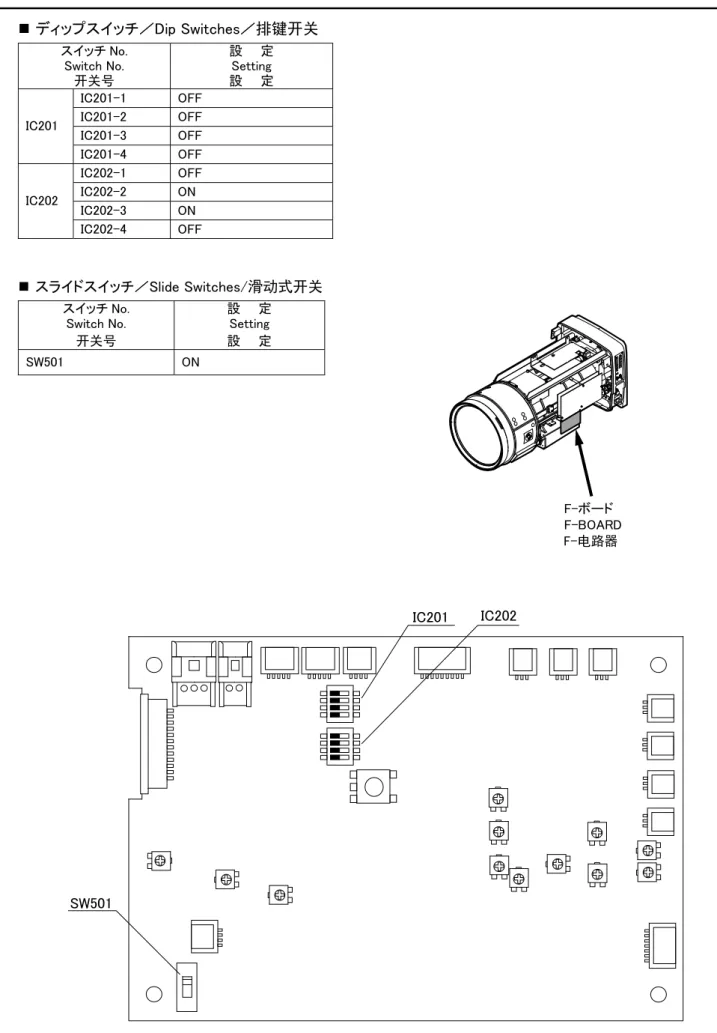
F. f 調整つまみ L F. f 固定つまみ OCKSM-21 7 -F.fマニュアル調整つまみによる調整 F.fマニュアル調整つまみによる調整 このレンズのフランジバック調整機構は、サーボ駆動方式となっています。 何らかの不具合で調整機構に電源が供給されない場合には、レンズ内部のF.fマニュアル調整つまみにより調整を 行ってください。 a. カバーを取り外します。 b. Fアンプ上のスイッチSW501を、OFF側にセットします。 c. ズームをワイド端にします。マニュアル調整つまみを回して、焦点を合わせます。 d. ズームをテレ端にします。フォーカスを操作して焦点を合わせます。 e. 正確な調整をするために、上記'c'、'd'を2~3回繰り返します。 注.F.f マニュアル調整つまみによる調整のとき以外では、SW501は、『ON』側にセットしておいてください。 F.f マニュアル調整つまみ IC201 IC202 SW501
F-アンプ
F-アンプ
ON (Normal) OFF(Manual) レンズ本体の両側にあるカバー取付つまみをゆるめ、カバーを前方に引くと外れます。SM-21 8 -* 文中のアクセサリの型名については、「オプショナルアクセサリ」の項を参照してください。
◇
1フォーカス操作
△
警告
レンズをカメラに取り付けた状態で、カメラを下方に45°以上傾けないでください。 レンズがカメラより落下して、重大な事故の原因となります。上記の姿勢で撮影をする必要がある場合には、 落下防止のための処置をレンズに施してください。操 作 方 法
2◇
ズーム操作
レンズに接続したコントロールユニットより操作を行います。コントロールユニットの操作方法については、コントロール ユニットの説明書を参照してください。 アイリスは、カメラ側からの信号 (オートアイリスまたはマニュアル) により制御されます。 また、レンズに接続したアイリスコントロールユニット (EIC-*) より操作を行なうこともできます。 アイリスコントロールユニットの操作方法については、アイリスコントロールユニットの説明書を参照してください。 レンズに接続したコントロールユニットより操作を行います。コントロールユニットの操作方法については、コントロール ユニットの説明書を参照してください。 EPD- * サーボ操作用コントロールユニット ・ フォーカスポジションデマンドユニット: マニュアル操作用コントロールユニット ・ フォーカスグリップ : BFH- * ERD- * サーボ操作用コントロールユニット ・ ズームレートデマンドユニット : マニュアル操作用コントロールユニット ・ ズームハンドル : BZH- * 3◇
アイリス操作
注.ショットボックス(ESB-6A-*)は、使用できません。SM-21 9
-◇
4エクステンダ切替操作
エクステンダ切替操作には、2つの方式があります。レンズのエクステンダ切替つまみを操作する「マニュアル 操作」と、アクセサリを使用する「アクセサリによる操作」です。 ■ マニュアル操作 レンズのエクステンダリモート/マニュアル切替スイッチを『MANU』に設定します。 レンズのエクステンダ切替つまみを操作して、エクステンダを切り替えます。 a. b. ■ アクセサリによる操作 レンジセレクタ、またはエクステンダ切替用のスイッチ等を搭載しているアクセサリを使用してエクステンダを切り替 えます。 5◇
マクロ操作
■ ズームコントロールユニットによる操作 レンズのマクロON/OFF切替スイッチを『ON』に設定します。 フォーカス操作用コントロールユニット (フォーカスポジションデマンドユニット等) を操作して、フォーカスを至近端 (M.O.D.) にします。 ズーム操作用コントロールユニットを操作して、被写体に焦点を合わせます。 ■ リモートマクロコントロールユニットによる操作 注. リモートマクロコントロールユニットでマクロ操作を行う場合には、レンズのマクロON/OFF切替スイッチは『OFF』に 設定しておいてください。 A: 1.2倍エクステンダに対応していないアクセサリ B: 1.2倍エクステンダに対応しているアクセサリ 1.2倍エクステンダに対応していないアクセサリを使用する場合は、以下の操作により 1倍/1.2倍/2倍を切り替えます。 1倍⇔2倍で切り替える場合は、レンズのエクステンダリモート/マニュアル切替スイッチを『REMOx1』側に設定 します。 1.2倍⇔2倍で切り替える場合は、レンズのエクステンダリモート/マニュアル切替スイッチを『REMOx1.2』側に 設定します。 a-1. a-2. 注. ※アクセサリの操作方法については、アクセサリの取扱説明書を参照してください。 a. b. c. マクロ操作は、レンズに接続したリモートマクロコントロールユニットより行います。 リモートマクロコントロールユニットの操作方法については、リモートマクロコントロールユニットの説明書を参照して ください。(リモートマクロコントロールユニットを使用しますと、カメラオペレータの手元でマクロ機能のON/OFFを 切り替えることができます。) マクロ操作 (近接撮影) は、ズーム操作用コントロールユニット (ズームレートデマンドユニット等)、 またはリモートマクロコントロールユニット (EA-3A-10A、11A等) から行うことができます。 アクセサリが 1.2倍エクステンダに対応している場合は、レンズに接続したアクセサリを操作して、エクステンダを 切り替えます。 複数の切替手段がある場合は、倍率の高い設定が優先されます。このため、カメラから2倍に設定されてい る場合には、アクセサリからの1.2倍、1倍設定は反映されません。アクセサリの指令に応じた切替を行うため には、カメラの設定を1倍にする必要があります。 注. 1.2倍エクステンダに対応していないアクセサリでは、アクセサリの倍率表示が実際と異なる場合がありま す。SM-21 10 -RV306
A-ボード
A-ボード
アイリスアンプの調整
カメラとの相性によって、アイリスの作動にハンチングを生じることがあります。このような場合には、下記のゲイン 調整を行ってください。なお、トリマの調整には、小型のマイナスドライバを使用してください。 ■ カバーの取り外し ■ ゲイン調整 a. カメラ側で、アイリス動作モードを”オート”に設定します。 b. 最初に、カバーを取り外してください。 レンズ本体の両側にあるカバー取付つまみをゆるめ、カバーを前方に引くと外れます。 ハンチングが起こらない範囲でアイリスゲインが最も高くなるように、A-ボードの『ゲイン調整トリマ』(RV306)を調整 します。SM-21 11 -このレンズには、フォーカス操作時に発生する画角の変化を補正するための機能が搭載されています。 この機能は、Aボード上のスイッチS704が『ON』の状態で使用できます。(スイッチS704は、工場出荷時にはOFF に設定してあります。) 補正機能は、 ズームの操作にデジタル仕様のズームレートデマンドユニット、フォーカスの操作にはデジタル仕様またはサー ボ仕様のフォーカスポジションデマンドユニットを使用している場合に働きます。
画角変化補正機能について
A-ボード
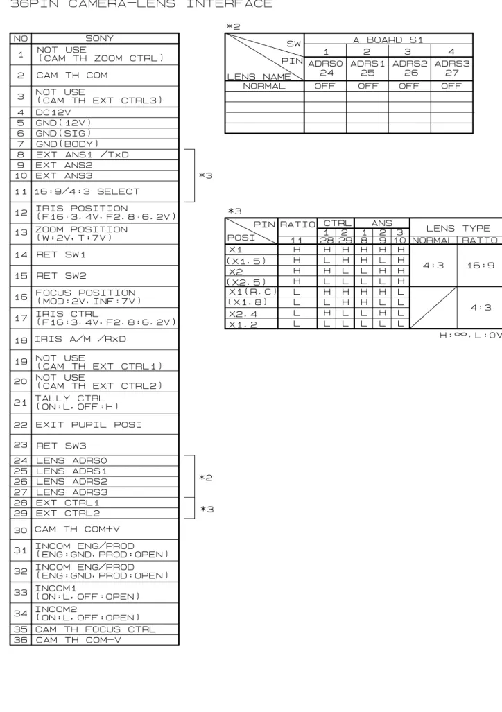
S704AD-7 12 -1. コネクタ ヒロセ HR25-9R-20S 2. コネクタのピンアサイン 下表の通り ピン 番号 信 号 1 N.C. 2 GND (デジタル) 3 N.C. 4 +5V(Zo 出力インピーダンス: 1kΩ) 5 N.C. 6 N.C. 7 N.C. 8 アイリスエンコーダ A 相(H: 5V、L: 0V) 9 アイリスエンコーダ B 相(H: 5V、L: 0V) 10 ズームポジション (W: 2V、T:7V)
11 防振 ON/OFF 信号 (ON: H、OFF: L)
12 ズームエンコーダ Z 相(H: 5V、L: 0V) 13 フォーカスポジション (N: 2V、F: 7V) 14 エクステンダ信号(×2:L(オープンコレクタ)) 15 基準電圧 5.0V 16 ズームエンコーダ A相(H: 5V、L: 0V) 17 ズームエンコーダ B 相(H: 5V、L: 0V) 18 フォーカスエンコーダ A相(H: 5V、L: 0V) 19 フォーカスエンコーダ B 相(H: 5V、L: 0V) 20 シグナル GND (アナログ) 3. 出力信号波形 4. 分解能 ・ フォーカス: 16 ビット ・ ズーム: 16 ビット ・ アイリス: 10 ビット (1) フォーカスエンコーダ出力信号波形 (無限遠側から至近方向へ動かしたとき) 時間 A相 B相 (2) ズームエンコーダ出力信号波形 (広角側から望遠方向へ動かしたとき) 時間 A相 B相 (3) アイリスエンコーダ出力信号波形 (クローズ側からオープン方向へ動かしたとき) 時間 A相 B相 Z相 * A相、B相に対するZ相の位置は規定しない
エンコーダ出力信号仕様
SM-21 13
-◇
1日常の整備
■ レンズの清掃 ■ 接続コード ■ 付 属 品 ■保 守 ・ 点 検
2◇
水分の除去
注. 市販のレンズクリーナまたはアルコールとエーテルを2対8の割合で混ぜた溶液、そしてレンズクリーニングペー パ ーまたは清浄な柔らかい木綿を用意します。 a. 初めに、レンズ表面のほこりを、柔らかい刷毛やブロアーブラシなどで払い落とします。 b. クリーニングペーパーを適当な大きさに折り、一部を溶液に浸します。ペーパーの湿った部分で、レンズの 中心部から周辺部に向けて、渦巻きを描きながら軽くふきます。 c. 新しいペーパーを使用して、ふき残りがなくなるまで ‘b’ の作業を繰り返してください。 ケーブルの外装やコネクタの端子が、ねじれや引っ張り、その他によって傷がついていないかどうか十分に点 検をしてください。 各種の付属品を使用して駆動伝達をさせる場合、お互いにかみ合う部分の全域にわたって形状に異常があっ たり、ごみ等の異物の付着や混入があってはいけません。取り付けを行う前に十分に点検をしてください。 異物を発見したときは速やかにこれを取り除いてください。 また、形状に異常が認められましたら、早めにサービスを受けられるようにお勧めします。 レンズキャップ レンズをカメラに取り付けたまま使用を中断する場合は、レンズの表面を保護するために必ずレンズキ ャップ を取り付けてください。 空気中の水分が、レンズ本体の内部に入りこんで各部品に付着すると、レンズにはやけを、また、金属部品 には錆等を発生させる原因になります。レンズ本体内部の水分は、次の方法に従って取り除いてください。 1. レンズ本体の外部に付着している水滴をふき取ります。次に、ビニール袋の中にレンズ本体と乾燥剤を入 れて密封し、乾燥剤の吸湿性を利用して水分を取り除きます。 2. レンズ本体の除湿を行うのに十分に時間的余裕のあるときは、外部に付着している水滴をふき取った後、 乾燥した部屋にこれを放置して水分を取り除いてください。 レンズ本体の容積、水分の付着の程度、使用する乾燥剤の量等の違いにより放置しておく時間も異なって きますが、最低でも3時間位は放置しておいてください。また、十分な吸湿効果を得るために乾燥剤は新し いものを使用してください。 3◇
レンズの保管
4◇
点 検
使用後のレンズはよく掃除して、必ずレンズキャップをはめてから収納箱に入れて保管してください。この場合、 高温多湿な所および腐食性ガスや塩分の多い所はさけてください。また、長期間使用しないときは、レンズを 時々収納箱から出して乾燥させてください。 ご使用上不都合が生じた場合には、購入先販売店にご相談ください。 長期間、高性能を維持していただくために、1年に1回の定期点検をお勧めいたします。 なお、お客様のご都合で改造等が行われた製品につきましては、点検・修理をお引き受けできないこともあり ますのでご注意ください。ENGLISH VERSION
この取扱説明書は「日本語版」「英語版」「中文版」「技術資料」から構成されています。 This operation manual is composed of the Japanese version, English version, Chinese version, and Technical Drawings.
日本語版 中文版 本使用手册包含日文版本英文版本中文版本技术资料。 日本語版 中文版 技术资料 English version 技術資料 Technical Drawings 技术资料 English version
技術資料/
Technical Drawings
/技术资料
中 文 版
ENGLISH
日 本 語
FCC REGURATIONS
CAUTION : Changes or modifications not expressly approved by the party responsible for compliance could void the user’s authority to operate the equipment.
Canadian Radio Interference Regulation
CAN ICES-3(A) / NMB-3(A)
CAUTION : This Class A digital apparatus complies with Canadian ICES-003.
This device complies with part 15 of the FCC Rules. Operation is subject to the following two conditions: (1) This device may not cause harmful interference, and (2) this device must accept any interference received, including interference that may cause undesired operation.
Note: This equipment has been tested and found to comply with the limits for a Class A
digital device, pursuant to part 15 of the FCC Rules. These limits are designed to provide
reasonable protection against harmful interference when the equipment is operated in a
commercial environment. This equipment generates, uses, and can radiate radio frequency
energy and, if not installed and used in accordance with the instruction manual, may cause
harmful interference to radio communications. Operation of this equipment in a residential
area is likely to cause harmful interference in which case the user will be required to correct
the interference at his own expense.
Disposal of Electrical and Electronic Equipment in Private Households
In the European Union, Norway, Iceland and Liechtenstein:
This symbol on the product, or in the manual, and/or on its packaging indicates that this product shall not be treated as household waste. Instead it should be taken to an applicable collection point for the recycling of electrical and electronic equipment.
By ensuring this product is disposed of correctly, you will help prevent potential negative consequences to the environment and human health, which could otherwise be caused by inappropriate waste handling of this product.
SM-21-T2/R1 i
-CONTENTS
■ FOR YOUR SAFETY USE・・・・・・・・・・・・・・・・・・・・・・・・・・・・・・・・・・・・・・・・・・・・・・・・・・・ⅱ
■ PRIOR TO USE・・・・・・・・・・・・・・・・・・・・・・・・・・・・・・・・・・・・・・・・・・・・・・・・・・・・・・・・・・ⅳ
・BEFORE INSTALLING ONTO CAMERA・・・・・・・・・・・・・・・・・・・・・・・・・・・・・・・・・・・・・・・・ⅳ
・CAUTION WHEN USING THE LENS-SUPPORTER・・・・・・・・・・・・・・・・・・・・・・・・・・・・・・・・ⅳ
・ENCLOSURE OF DESICCANT・・・・・・・・・・・・・・・・・・・・・・・・・・・・・・・・・・・・・・・・・・・・・・・ⅳ
・SELECTION OF CAMERA・・・・・・・・・・・・・・・・・・・・・・・・・・・・・・・・・・・・・・・・・・・・・・・・・・ⅴ
・SETTING OF CAMERA MODE・・・・・・・・・・・・・・・・・・・・・・・・・・・・・・・・・・・・・・・・・・・・・・・ⅵ
■ GENERAL DESCRIPTION・・・・・・・・・・・・・・・・・・・・・・・・・・・・・・・・・・・・・・・・・・・・・・・・・・・ 1
■ LIST OF COMPONENTS・・・・・・・・・・・・・・・・・・・・・・・・・・・・・・・・・・・・・・・・・・・・・・・・・・・・ 1
■ SPECIFICATIONS・・・・・・・・・・・・・・・・・・・・・・・・・・・・・・・・・・・・・・・・・・・・・・・・・・・・・・・・ 2
■ NAMES AND FUNCTIONS ・・・・・・・・・・・・・・・・・・・・・・・・・・・・・・・・・・・・・・・・・・・・・・・・・・ 3
■ INSTALLATION ・・・・・・・・・・・・・・・・・・・・・・・・・・・・・・・・・・・・・・・・・・・・・・・・・・・・・・・・・ 5
■ ADJUSTMENT OF FLANGE FOCAL LENGTH ・・・・・・・・・・・・・・・・・・・・・・・・・・・・・・・・・・・・ 6
■ OPERATING INSTRUCTION・・・・・・・・・・・・・・・・・・・・・・・・・・・・・・・・・・・・・・・・・・・・・・・・・ 8
ADJUSTMENT OF IRIS AMPLIFIER・・・・・・・・・・・・・・・・・・・・・・・・・・・・・・・・・・・・・・・・・・10
■ ABOUT FUNCTION OF COMPENSATION FOR CHANGE OF FIELD ANGLE・・・・・・・・・・・・・・11
■ SPECIFICATIONS OF ENCODER OUTPUT SIGNAL・・・・・・・・・・・・・・・・・・・・・・・・・・・・・・・12
MAINTENANCE・・・・・・・・・・・・・・・・・・・・・・・・・・・・・・・・・・・・・・・・・・・・・・・・・・・・・・・・・・・13
DAILY MAINTENANCE・・・・・・・・・・・・・・・・・・・・・・・・・・・・・・・・・・・・・・・・・・・・・・・・・・・13
ELIMINATION OF WATER・・・・・・・・・・・・・・・・・・・・・・・・・・・・・・・・・・・・・・・・・・・・・・・・13
STORAGE OF LENS・・・・・・・・・・・・・・・・・・・・・・・・・・・・・・・・・・・・・・・・・・・・・・・・・・・・・13
INSPECTION・・・・・・・・・・・・・・・・・・・・・・・・・・・・・・・・・・・・・・・・・・・・・・・・・・・・・・・・・・13
4 1◇
◇
◇
◇
■
24 5
■
◇
◇
◇
◇
1 2 3EXTENDER SELECTION・・・・・・・・・・・・・・・・・・・・・・・・・・・・・・・・・・・・・・・・・・・・・・・・・・ 9
MACRO OPERATION・・・・・・・・・・・・・・・・・・・・・・・・・・・・・・・・・・・・・・・・・・・・・・・・・・・・・ 9
◇
FOCUSING OPERATION・・・・・・・・・・・・・・
3
・・・・・・・・・・・・・・・・・・・・・・・・・・・・・・・・・・・・ 8
ZOOMING OPERATION・・・・・・・・・・・・・・・・・・・・・・・・・・・・・・・・・・・・・・・・・・・・・・・・・・・ 8
IRIS OPERATION・・・・・・・・・・・・・・・・・・・・・・・・・・・・・・・・・・・・・・・・・・・・・・・・・・・・・・ 8
FOR YOUR SAFETY USE
E1462/R4 ii
-FOR YOUR SAFETY USE
This content explains important notices for all the users to use this product safely. Read the
content carefully before using, and follow the instructions.
The following signs show:
Do not attach something to the lens other than Fujinon optional accessories that are designed to be attached to the lens; do not put something on the lens. An abnormal object attached to or on the lens may fall in operation of the camera causing a serious accident.
Do not look at any sorts of strong illuminant such as the sun through the lens. Eyes could be harmed.
◆ Be sure to attach all the parts securely. Dropping any parts from a height may cause severe accidents.
WARNING
Do not moisten inside of the appliances. It may cause fire or electric shock. If the incident occurs, shut off the power supplied to the lens immediately.
If the camera is declined by 45 degrees or more, there may be a case that the lens installed on the camera falls. If it is required to shoot an object with the camera in the posture stated above, before using the camera, a proper measure should be taken on the lens to avoid falling.
◆ Before operating the camera, confirm that there is no object in the range of camera movement. If the lens is bumped against an object with a strong force, there may be a case that the lens falls from the camera causing a serious accident.
Indicates what the user “should not do.”
WARNING
Indicates the possibility of causing death or serious injury when misused.
CAUTION
Indicates the possibility of causing injury or substantial damage when misused.
FOR YOUR SAFETY USE
E1462/R4 iii
-△
CAUTION
◆ Take care when carrying the lens. Dropping the lens while carrying may cause injury. ◆ Before supplying the power to the lens, make sure all the parts are connected correctly.
◆ In order to install or release the lens cable, be sure to hold the joint part. Do not damage the cable by gripping. It may cause fire or electric shock.
◆
NOTICE
◆ Lens and its accessories are extremely precise instrument, then be sure not to apply the strong impacts to them. If the lens is of a type in which the rear lens protrudes from the flange surface of the lens mount, be sure not to apply impact to the lens part when installing or releasing.
◆ There may be a case that the glasses of the lens mist when the lens is carried from a cool place to a place of high temperature and high humidity. To avoid a mist on the glasses, before moving the lens, let the lens adjust to the ambient temperature of the place where the lens will be used.
◆ Be sure not to apply impact to the front part of the lens when operating the camera. ◆ Put the cap on the lens while the camera is not used.
◆ If an accessory to be attached to the lens is equipped with a mechanical drive relaying part, before attaching it, check the joint part and get rid of all obstacles. If there are any unusual conditions, please contact the sales agent from which you purchase the product.
◆ When the lens is used in the weather of fog, raining, or snowing, cover up the lens to prevent it from the water. ◆ To minimize the impact to the lens in transportation, set the zoom to the wide end and the focus to the infinity
side end before releasing the lens from the camera.
If any sorts of incidents such as unusual smoke, noise, smell or obstacles are found, shut off the power supplied to the lens and pull out the lens cable immediately. Please notify the sales agent from which you purchased the lens. ◆ Do not remodel the product: it may impair the functions of product or cause electric shock.
NT66-1 ⅳ
-■ Before Installing onto Camera
When it is required to install this lens on a Sony studio camera (Ex. HDC-2000) or on a Sony large lens adapter (Ex. HDLA-1500), remove the pin on the bayonet mount of the lens, and attach it to the threaded hole in the mount frame. To install this lens on another camera, reinstall the pin on its former position.
THREADED HOLE
PIN
PRIOR TO USE
There are five desiccant bags in the trunk. Take out two of them to use. The rest should be used when the exchange of the desiccant is required.
Loosen the two lens shroud attaching knobs on the both sides of the lens. Draw the shroud towards the front of the lens to detach it from the body.
Remove the four screws to take off the lid. Take out the desiccant bag for storage.
Fold two new desiccant bags and put them in the desiccant enclosure place.
Put the detached lid in its place and reinstall the four screws. Finally, reinstall the lens shroud. Note 1. Perform the above procedure in a dust-free place.
Note 2. a. b. c. d. e. f.
NEW DESICCANT BAG
DESICCANT BAG FOR STORAGE
DESICCANT ENCLOSURE PLACE
In a humid region, it is recommended to change the desiccant bags two times a year. The desiccant being jellied indicates the time when it must be exchanged.
■
■ Enclosure of Desiccant
The inside of this lens is able to enclose desiccant in order to eliminate humidity that may mist the surfaces of the internal glasses. A desiccant bag for storage was enclosed in the desiccant enclosure place before shipment at the factory. Prior to use, take out this bag first, and put new desiccant bags in that place as follows:
Cautions when using the lens supporter
When using this lens with a Fujinon lens supporter (ELH-*) attached, use a power source connecter (see “Name and Function of Each Part”) to supply power from the lens side. If power is not supplied, correct operation may not occur.
PRIOR TO USE
NT58-2 v
-■Selection of Camera
The behavior of the intercom select switch in an accessory differs by types of camera. If required, change the setting of dip switch (S710-7) on the A-board in the lens according to the type of camera.
At the factory, the switch is set to “TYPE 1.”
The circuits relative to the dip switch are shown below.
Note. If the camera is of TYPE 2, set the intercom select switch on the camera side to “PD.” At the position of “ENG,” “PD” can not be selected from a zoom rate demand unit.
Setting of Dip Switch (S710-7) OFF: Camera Type 1
ON: Camera Type 2
1 2 3 4 5 6 7 8 O N
Ⅰ. TYPE 1 CAMERA: BVP-270 series (NTSC) and BVP-370 series (NTSC)
INCOM 1 SW ENG
PD ACCESSORY
(EX. ERD-5A-D01/ERD-5A-D11) LENS
Ⅱ. TYPE 2 CAMERA: BVP-370 series (PAL)
INCOM SETTING LINE ENG
PD ACCESSORY (EX. ERD-5A-D01/ERD-5A-D11) LENS INCOM 2 SW CAMERA INCOM (1) SW CAMERA
A-BOARD
A-BOARD
S710NT58-2 vi
-■Setting of Camera Mode
If the camera to be used with is not capable of serial communication with a lens, set the communication mode (camera mode) of the lens to OFF.
Note. Before shipping at the factory, S703 is set to ON. Setting Method
S703
A-BOARD
First, remove the shroud. The shroud can be removed by pulling it towards the front after loosening the two lens shroud attaching knobs on both sides of the lens.
The switch S703 (on A-board) can be seen on the right-hand side (viewed from front of lens) of the lens by removing the lens shroud. Set this switch to “OFF.”
1
-Fujinon TV lens of UA80 × 9 series is a high performance zoom lens designed for 2/3" format 4K-UHD TV.
Its super high zoom ratio of 80 times and a built-in 1.2 and 2 times range extender make it super narrow angle zoom lens with a maximum focal length of 1440 mm. In spite of super high zoom ratio, the maximum relative aperture is 1:1.7. With all features described above, this lens is compact in size and light in weight, therefore the lens is particularly useful for field applications.
This lens is equipped with an anti-vibration mechanism. With this mechanism, even in the location in the strong wind or on an unsteady platform, a stable image can be derived thanks to the vibration detecting sensor and the compensating optical system in the lens.
This lens is a digitally controlled lens incorporating a 32 bit RISC (Reduced Instruction Set Computer) CPU. By digital processing with a RISC CPU, this lens can be controlled precisely. Besides, this lens is equipped with an interface for communication with a computer; there-fore it can be controlled from a remote computer.
■Standard Components
GENERAL DESCRIPTION
LIST OF COMPONENTS
1.Lens package・・・・・・・・・・・・・・・・・・・・・・・・・・・・・・・・・・・・・・・・・・・・・・・・・・・・・・・・・・・・・・・・・・・・ 1 ・Front lens cap・・・・・・・・・・・・・・・・・・・・・・・・・・・・・・・・・・・・・・・・・・・・・・・・・・・・・・・・・・・・・・・・ 1 ・Rear lens cap・・・・・・・・・・・・・・・・・・・・・・・・・・・・・・・・・・・・・・・・・・・・・・・・・・・・・・・・・・・・・・・・・ 1 2.Cleaning kit・・・・・・・・・・・・・・・・・・・・・・・・・・・・・・・・・・・・・・・・・・・・・・・・・・・・・・・・・・・・・・・・・・・・ 1
LP550A-S35/R0 2
-LENS
ITEM
UA80×9BESM-S35E
Application 2/3” Format Color Camera (Prism Optical System)
Aspect Ratio 16 : 9
Image Format 9.59 × 5.39 mm (φ11.0 mm)
Focal Length
Zoom Ratio 80×
(F No.) Maximum Relative Aperture
Iris Range F1.7 ~ F16、Closed
Flange Focal Length (in Air) See Fig. 1. Minimum Object Distance
(from Front of Lens) 3.7 m (0.3 m in Macro Operation) Field Angle
Hor. Ver. Diag. at Wide End Object Area at M.O.D.
at Tele End
Iris Control Servo
Zoom Control Servo (Min. Op. Time: Approx. 1 s *3) or Manual
Focus Control Servo (Min. Op. Time: Approx. 0.8 s) or Manual Anti-vibration Mechanism
Direction of Compensation Adaptable Frequency Amount of Compensation
Vertical+Horizontal or Vertical Only
3~10Hz
40% of Vertical Image Size (at Telephoto End w/o 2× Extender)
Mount See Fig. 1.
(at 12V DC)
Power Consumption 9.6 W (Quiescent)
27 W (Maximum)
Mass 23.5 kg (Approx.)
*1 The values in the Japanese-style quotation marks ( < > ) are given when the 1.2× range extender is used.
*3 With the zoom high speed servo module, the minimum operating time is about 0.6 sec.
SPECIFICATIONS
Operation range of tilt ±45°
9.0~ 720 mm <10.8 ~ 864 mm> *1 [18.0 ~ 1440 mm] *2
F1.7 (9.0~350 mm)~F3.5 (720 mm) [F2.0~F4.2]*1 [F3.4 ~ F7.0] *2
*2 The values in the square brackets ( [ ] ) are given when the 2× range extender is used. <47゜53’~ 0゜38’>*1 <28゜01’~ 0゜21’> <53゜59’~ 0゜44’> 56゜06’~ 0゜46’ 33゜20’~ 0゜26’ 62゜52’~ 0゜53’ [29゜50’~ 0゜23’]*2 [17゜02’~ 0゜13’] [33゜59’~ 0゜26’] 3501×1968 mm 46× 26 mm <3009×1692 mm>*1 < 39× 22 mm> [1816×1021 mm]*2 [ 23× 13 mm]
3
-NAMES AND FUNCTIONS
Note. The encircled numbers indicate the numbers in the outline drawing (Fig. 1). ① Tally Lights (2 places)② Handles (2 places)
To carry this lens, hold these handles with both hands. ③ Shroud Attaching Knobs (2 places)
The knobs to fix the lens shroud to the body of the lens. ④ Extender Remote/Manual Select Switch
To select the extender manually, set this switch to “MANU.”
To select the extender using a remote control unit and the extender range between 1x and 2x, set this switch to “REMOx1.” To select the extender range between 1.2x and 2x, set this switch to “REMOx1.2.”
⑤ Extender Select Knob
The extender manual selection is performed by means of this knob. ⑥ Zoom, Iris, Extender Indicator
This indicator shows the present positions of the zoom, iris and extender. ⑦ Indicator ON/OFF Select Switch
Operation of this switch can select ON or OFF of “Zoom, Iris, Extender Indicator.” ⑧ Hood
This hood prevents the extra light from entering the lens. ⑨ Servo Modules (2 places)
To control the lens with servo control units, install servo modules. ⑩ Manual Modules (2 places)
To control the lens with manual control units, install manual modules. ⑪
⑫ Connector for Macro Control
This connector is provided for a macro control unit. ⑬ Connector for Encoder Output
The connector for outputting digital signals derived from the iris, focus, and zoom encoders. For the output signal, refer to section “Specifications of Encoder Output Signal” on page 12. ⑭ Connector to Range Selector
This connector is provided for either a range selector or an iris control unit (refer to page 9). ⑮ Connector for Stabilizer Control
This connector is provided for an optical stabilizer control unit with which the camera operator can select the optical stabilizer function of the lens. (To select the optical stabilizer function using an optical stabilizer control unit, set the stabilizer H+V/OFF/V select switch of the lens to OFF.)
In either self-diagnosis operation using a Fujinon Find System or remote-control operation using a computer, the communication with a computer can be made through this connector. The RS-232C connecter is located inside the lens. When it is required to control the lens using a personal computer, detach the partial cover under the connector.
The cover can be detached by removing the four screws that attach the cover.
(For the lens control protocol, contact the sales agent from which you purchased the lens.)
RS-232C Connector
⑫
⑮
Connector forStabilizer Control
⑭
⑬
Connector for Encoder OutputConnector for Macro Control
Connector to Range Selector
4
-CONNECTOR ITT CANNON (XLR-4-32-F152)
Pin 1 GND (0V)
Pin 2 NC
Pin 3 NC
Pin 4 +12V(+12~+16V),More than 3A
⑰ F.f Locking Knob
This knob secures the F.f adjusting knob. ⑱ Bayonet Mount
The bayonet type mount used in installation onto a portable camera. ⑲ Pin
In installation of the lens, align this pin with the appropriate hole in the mounting surface of the camera or the lens supporter.
⑳ Hook
In installation of the lens, hang this hook on that on the mounting surface of the camera or the lens supporter. ㉑ Pin
In installation of the lens onto a portable camera, align this pin with the hole in the mounting surface of the camera.
㉒ Spring Pin
In installation of the lens, this spring pin enters the appropriate hole in the mounting surface of the camera or the lens supporter and prevent shaking of the lens.
㉓ Connector to Camera
㉔ Macro ON/OFF Select Switch
㉕ Tally Lights HIGH/LOW/OFF Select Switch
㉖ Connector for Focus, Zoom Control
㉗ Connector for Power Source
This connector is provided for a DC power source. If the camera is not able to supply sufficient electric power to the lens, use a DC power source.
㉘ Stabilizer H+V/OFF/V Select Switch
With this switch set to “H+V,” the optical stabilizer functions responding to the vibration of both vertical and horizontal directions, while set to “ V, ” it functions responding to the vibration of only vertical direction. When this switch is set to “OFF,” the anti-vibration mechanism does not operate. (When an optical stabilizer control unit is connected to this lens, the setting of the select switch on the optical stabilizer control unit has priority to the setting of this switch.)
㉙ Stabilizer HIGH/STD. Select Switch
(When an optical stabilizer control unit is connected to this lens, the setting of the select switch on the optical stabilizer control unit has priority to the setting of this switch. If the optical stabilizer control unit connected to this lens is not equipped with a select switch, the stabilizing characteristic cannot be changed.)
⑯ F.f Adjusting Knob
The flange focal length of the lens is adjusted by means of this knob.
This connector is provided for a connection cable, one or two ends of which are connected to a focus control unit and a zoom control unit.
The intensity of illumination of the tally lights can be selected from High or Low intensity.
When the switch is set to OFF, the tally lights go out. With this switch set to ON, the macro operation (taking a close-up shot) can be performed.
Mount a cap on the power connector towards the horizontal.
The suitability of stabilizing characteristic mode settings and pan and tilt operation by the operator is shown in the table at right.
Pan and Tilt Operation MODE
Yes No
STD ○ ◎
HIGH ◎ ○
◎=Optimal 〇=Suitable
The stabilizing characteristic of the optical stabilizer can be selected by means of this switch. The electrical connection with the camera is made through
5
-Note 1.
Note 2. After installation, when the power of the camera is turned on, the initial settings of the stabilizer mechanism and the main lens are carried out for about ten seconds and several seconds respectively at the same time.
During the setting of the stabilizer mechanism, do not perform panning or tilting operation of the camera; the indicator of the optical stabilizer control unit linked to the lens blinks.
During the setting of the main lens, the operation of the lens cannot be performed. After the setting, the zoom returns to its former position.
Be sure to attach all the parts securely. Dropping any parts from a height may cause severe accidents.
a.
b.
c.
Note. Make sure to adjust the flange focal length when installing the lens on a camera for the first time or installing it on another camera (refer to the next page for details).
HOOKS
LENS CAMERA
LENS MOUNT LOCKING KNOB
I N S T A L L A T I O N
Description in this section applies to installation of a lens onto a studio camera.
For installation onto a portable camera, a lens supporter is required. Refer to the operation manual of the lens supporter.
Prior to installation, turn off the power of the camera.
△
WARNING
■ Installation onto Studio Camera
Holding the lens package with both hands, hang the hook at the top rear of the package on the hook at the top front of the camera, and align the pin on the lens mount with the groove in the camera mount.
Swing the package down so that the spring pin on the lens mount gets in the hole in the camera mount. In this procedure, the electrical connections, via the connectors on both mounting surfaces, is automatically made. Securely fix the lens package by means of the lens mount locking knob attached to the camera mount.
6 -■ Conditions of Object and Iris Position
The flange focal length is the distance from the flange (mounting surface) of a lens to the focal plane.
ADJUSTMENT OF FLANGE FOCAL LENGTH
■ Adjustment Note.
Carry out the adjustment observing a monitor.
REAR RIGHT-HAND VIEW
F.f ADJ. KNOB L F.f LOCKING KNOB OCK 1. Object 2. Object distance 3. Iris position
: an object that provides clear and easy focusing even at the wide end : about 7.5m (measured from front glass of the lens)
: maximum aperture or near that condition If the focal plane of the lens does not coincide with the image plane of the camera, the object will be out of focus during a zoom operation.
To prevent this from happening, the adjustment of the flange focal length is required.
Make sure to carry out the adjustment when installing the lens to a camera for the first time or installing it to another camera.
Before adjustment, set the macro ON/OFF select switch on this lens to OFF. If a remote macro control unit (EA-3A-10A, 11A, etc) is linked to this lens, set the remote macro ON-OFF select switch on the unit to OFF.
For the operation of focusing and zooming, refer to sections “Focusing Operation” and “Zooming Operation (pages 11 and 12).
a. Loosen the F.f locking knob by rotating it counterclockwise.
b. At the wide end in the zoom range, focus on the object by means of the F.f adjusting knob. c. At the tele end, focus on the object by means of a focus control unit.
d. Repeat steps ‘b’ and ‘c’ several times so that the F.f is adjusted completely. e. Finally tighten the F.f locking knob by rotating it in the direction of the arrow.
Focal Plane
Flange Focal Length Flange