E ffi cient data transport technologies for next generation backbone network
February 2010
Graduate School of Science and Technology Keio University
Sho SHIMIZU
i
Contents
Summary 1
1 Introduction 3
1.1 Background . . . . 3
1.2 Requirements for next generation backbone network . . . . 6
1.3 Position of the dissertation . . . . 7
2 Backbone network technologies 14 2.1 Fundamental technologies . . . . 14
2.1.1 Wavelength Division Multiplexing (WDM) . . . . 14
2.1.2 Generalized Multi-protocol Label Switching (GMPLS) . . . . 16
2.1.3 Carrier grade Ethernet . . . . 19
2.1.4 Content Delivery Network (CDN) . . . . 22
2.2 Previous works . . . . 23
2.2.1 Routing and Wavelength Assignment (RWA) . . . . 23
2.2.2 Path calculation . . . . 30
2.2.3 Replica placement problem. . . . 32
3 Wavelength assignment scheme for high speed and large capacity WDM networks 38 3.1 Abstract . . . . 38
3.2 Introduction . . . . 39
3.3 System model . . . . 41
3.3.1 Routing . . . . 41
3.3.2 Wavelength reservation protocol . . . . 42
3.3.3 Limited-range wavelength converter . . . . 43
3.3.4 First-Fit assignment . . . . 44
3.4 Proposed scheme . . . . 45
3.4.1 Wavelength assignment at the source node. . . . 46
3.4.2 Wavelength assignment at intermediate nodes . . . . 48
3.5 Performance evaluation . . . . 49
3.6 Conclusion . . . . 57
4 Scalable layer 2 network architecture using VLAN tag swapping 61 4.1 Abstract . . . . 61
4.2 Introduction . . . . 61
4.3 Wide area Ethernet architecture . . . . 63
4.4 Experiments . . . . 66
4.4.1 Experimental setup . . . . 66
4.4.2 Path establishment . . . . 67
4.4.3 High definition video transmission and numerical results . . . . . 67
4.5 Conclusion . . . . 69
5 Parallel shortest path search algorithm for sophisticated traffic engi- neering 77 5.1 Abstract . . . . 77
5.2 Introduction . . . . 77
5.3 Related works . . . . 79
5.3.1 Shortest path algorithm . . . . 79
iii
5.3.2 Reconfigurable processor. . . . 80
5.4 Multi-route parallel search algorithm . . . . 81
5.4.1 Summary . . . . 81
5.4.2 Matrix representation . . . . 82
5.5 Evaluation . . . . 86
5.6 Hardware off-loading engine prototype . . . . 89
5.6.1 MPSA implementation on DAPDNA-2 . . . . 90
5.6.2 Integration with GNU Zebra . . . . 92
5.7 Conclusion . . . . 93
6 Optimal application framework for distributing large volume data 97 6.1 Abstract . . . . 97
6.2 Introduction . . . . 97
6.3 Replica placement problem . . . . 100
6.4 Proposed method . . . . 105
6.4.1 Beeler’s algorithm and any-order pattern algorithm . . . . 106
6.4.2 Optimal number of divisions . . . . 108
6.4.3 Implementation on DAPDNA-2 . . . . 109
6.5 Performance evaluation . . . . 110
6.6 Conclusion . . . . 117
7 Conclusion 122
List of the Related Papers 126
Acknowledgments 134
Lists of Figures
1.1 Traffic volume observed at JPIX . . . . 5
1.2 Relationship between the requirements and the research topics . . . . 8
1.3 Position of this dissertation . . . . 9
2.1 Illustration of the LSP hierarchy in GMPLS . . . . 18
2.2 Frame formats of PBB, the original Ethernet, VLAN, and provider bridge 22 2.3 Origin server and replica servers in CDN . . . . 24
2.4 Classification of RWA algorithms . . . . 25
2.5 Classification of the target network of researches on RWA. . . . 26
3.1 Forward reservation . . . . 41
3.2 Limited-range wavelength Converter (W = 7,k= 1,i= 4). . . . 42
3.3 Converted wavelength signal power model . . . . 44
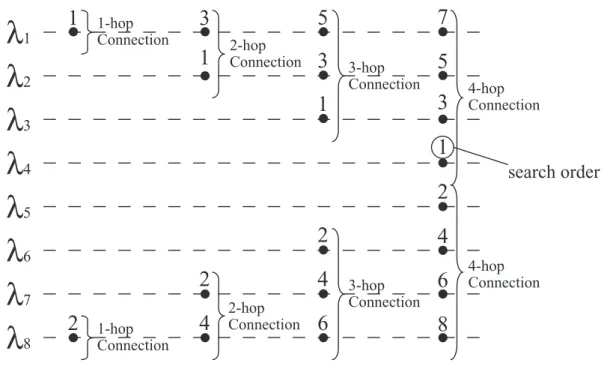
3.4 Search area and search order of the proposed scheme at the source node (W =8,Hmax= 4) . . . . 45
3.5 Search order of the proposed scheme at intermediate nodes (W = 10,k =2) 46 3.6 The effect of the proposed scheme . . . . 47
3.7 Network topology used in computer simulations . . . . 48
3.8 Pan European Network . . . . 49
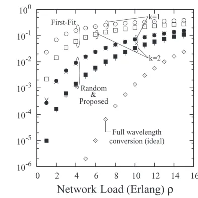
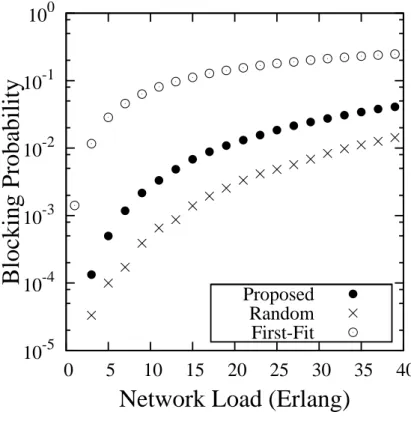
3.9 Blocking probability versus network load ρon the 8-node unidirectional ring network. . . . 50 3.10 Blocking probability versus network loadρon the 14-node NSFNet network 51
v 3.11 Blocking probability versus network loadρon the 28-node Pan European
Network . . . . 52
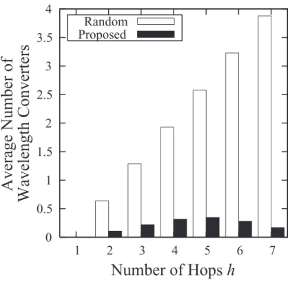
3.12 The average number of wavelength conversions needed versus the number of hops on the 8-node unidirectional ring network (ρ=7.0,k =1) . . . . 53
3.13 The average number of wavelength conversions needed versus the number of hops on the 14-node NSFNet network (ρ=11.0,k= 1) . . . . 54
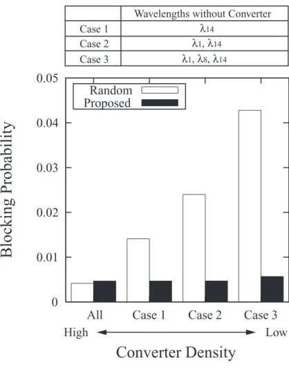
3.14 Blocking probability versus wavelength converter density (ρ =3.0,k=1) on the 8-node unidirectional ring network . . . . 55
3.15 Blocking probability versus wavelength converter density (ρ = 11.0,k = 1) on the 14-node NSFNet network . . . . 56
3.16 Increase ratio of blocking probability versus network load in case that three wavelength converters are reduced . . . . 57
4.1 Centralized wide area Ethernet . . . . 63
4.2 Decentralized wide area Ethernet . . . . 64
4.3 VLAN tag swapping . . . . 66
4.4 Signaling sequence of L2-LSP establishment . . . . 70
4.5 Experimental setup of demonstration . . . . 71
4.6 Click configuration . . . . 72
4.7 Changing configurations of a switch when signaling is occurred . . . . . 72
4.8 Round trip time between user01 and user02 . . . . 73
4.9 UDP throughput between user01 and user02 . . . . 73
4.10 High definition video sender, receiver, and 2 edge switches placed in Keio University, Japan . . . . 74 4.11 4 Core switches placed in the ilab.t testbed in Ghent University, Belgium . 74 4.12 High definition video captured by video camera is displayed on TV monitor 75
5.1 Our proposed algorithm finds the shortest paths by simultaneous multi-
path search . . . . 83
5.2 Example of Operation C where it is assumed data length of an element is 4 bits. . . . 85
5.3 The data-flow of the matrix representation of MPSA. . . . 86
5.4 The execution time versus the number of nodes in Dijsktra’s algorithm and MPSA. . . . 88
5.5 The Image of DAPDNA-EB4 . . . . 89
5.6 High level design of our implementation and splitting into three configu- rations . . . . 91
5.7 The flowchart of reconfigurations . . . . 94
5.8 The architecture of our prototype . . . . 94
5.9 DAPDNA-EB4 is plugging into a PCI slot . . . . 95
6.1 Origin server and replica servers{1, 5}can cover all nodes when the qual- ity requirement is 8. . . . . 101
6.2 First data of each group are entered per clock cycle by pipeline operation. DNA matrix outputs Data2, Data7, Data12 and Data17, which are the next input data. . . . . 105
6.3 DAPDNA-2 can reduce the execution time by 40 times compared to Pen- tium 4 when the number of nodes is 30. . . . . 112
6.4 Theoretical execution time versus the number of nodes when the number of replicaskis 25 percent of the number of nodesn . . . . 113
6.5 Theoretical execution time versus the number of nodes when the number of replicaskis 12.5 percent of the number of nodesn . . . . 114
6.6 Theoretical execution time versus the number of nodes when the number of replicaskis 50 percent of the number of nodesn . . . . 115
vii 6.7 Theoretical execution time versus the number of nodes when the number
of replicaskis 75 percent of the number of nodesn . . . . 116 6.8 Theoretical execution time versus the number of partitions . . . . 117 6.9 Comparison of the optimality of Greedy-Cover and the proposed algorithm 118 6.10 Comparison of the execution time of Greedy-Cover and the proposed al-
gorithm . . . . 119
Lists of Tables
5.1 The latency of each matrix operation unit . . . . 88
1
Summary
The backbone network traffic generated by the Internet continues to grow rapidly due to the emergence of many new broadband access services such as VoIP, P2P, video sharing like YouTube, and grid computing. WDM technologies can allow the backbone network to support the explosive growth in bandwidth demands. However, many of the new ap- plications require different communication topologies and multi-layer operation, such as WDM, TDM, and packet layer. To fully support these and yet-to-be introduced services, new highly efficient communication network schemes are needed. This dissertation iden- tifies efficient data transport technologies for the next generation backbone networks.
There are four requirements for next generation backbone network to handle rapidly increasing traffic volume and support emerging applications: 1) high speed and large capacity, 2) scalability, 3) traffic engineering capability, and 4) application frameworks for large data distribution. Topics to satisfy these requirements are investigated in Chapter 3 – 6. This dissertation is organized as follows.
Chapter 1 describes the background of this dissertation and clarifies its purpose and position.
Chapter 2 illustrates fundamental technologies for next generation backbone network and previous works related to the above requirements.
Chapter 3 focuses on high speed and large capacity transport. A novel wavelength as- signment scheme for a wavelength-routed network with wavelength converters of limited range is proposed. It reduces the total number of wavelength conversions needed and the
number of wavelength converters. Consequently, it makes wavelength-routed networks cost effective.
Chapter 4 focuses on the scalability issue of the next-generation layer-2 network. The VLAN tag-swap-based wide area layer-2 networks architecture is proposed for the scal- able next generation layer 2 network in this chapter.
The computational complexity of path calculation in traffic engineering is the focus of Chapter 5. The new approach of parallel shortest path search is proposed to realize sophisticated traffic engineering. The proposed approach uses dynamically reconfigurable processors (DRPs), and takes full advantage of their parallelism.
Chapter 6 focuses on an application framework for large data distribution, and intro- duces a new solution to the replica placement problem that is found in content delivery networks. The solution, which takes the form of application level technology, is specifi- cally designed to achieve the efficient distribution of large volume contents. The proposed replica placement solution can generate all replica placement patterns at extremely high rates due to DRP parallelism. Optimal replica placement, which means the minimum number of replicas, can be obtained within reasonable time. The proposal is expected to trigger the emergence of exciting new cost-effective services based on large volume content distribution.
Chapter 7 draws this dissertation to its conclusion with a useful summary of the ad- vances raised herein.
3
Chapter 1
Introduction
1.1 Background
The development of the Internet has changed our daily lives drastically. The Internet originates from the research project of the Advanced Research Project Agency (ARPA), which is an agency of the United States Department of Defense. The research project was called ARPANET at that time. In 1990s, the commercial use of the Internet was permitted, then many commercial services have been emerged. A typical commercial service in the early age of the Internet is connecting to the Internet. The service for home and business users began, and Internet Service Providers (ISPs) appeared.
The first breakthrough in terms of the development of the Internet was the invention of the World Wide Web (WWW). The WWW was invented in 1990 by Tim Bernes-Lee, who was working at the European Organization for Nuclear Research (CERN). The first web browser and the web server were developed on the NeXT STEP platform. After that, the WWW became a popular application on the Internet. One of the advantages of the WWW is hypertext structure, which links some information with related information.
The WWW enabled us to retrieve a lot of information through the Internet easily, and also to distribute information by ourselves at low cost.
As the development of the WWW, the size of the contents on the web has been in- creasing. Originally, the contents were text-based information, which sometimes includes small (low resolution) still images. The access speed around 1995 was typically limited
to 64kbps since the normal way to access to the Internet was dial-up access. As a re- sult, the total size of a web page was several or tens of kilo bytes. From the late 1990s to the early 2000s, several broadband access service like Asymmetric Digital Subscriber Line (ADSL) and Fiber To The Home (FTTH) has started. Currently, these broadband access network is in majority. Especially in Japan, the most popular broadband access is FTTH [1]. The total number of subscribers of FTTH is increasing while that of ADSL is decreasing. Therefore, a web page includes large volume contents such as large (high resolution) still images, sounds, and moving images.
Figure 1.1 shows the traffic volume of the backbone network observed at Internet eX- change (IX) of Japan Internet eXchange (JPIX) [2]. JPIX is the first commercial IX in Japan, which is founded by major network companies in 1997. The backbone Internet traffic in Japan has been increasing due to the development of broadband access technolo- gies. Currently, the minimum traffic volume observed at JPIX reaches 50Gbps, and the maximum traffic volume is over 150Gbps. How to manage the increasing traffic is a big issue in backbone networks. From this perspective, next generation backbone network has to provide high speed and large capacity network.
The number of the Internet users has been increasing for about last 10 years since the price to connect to the Internet has been decreasing and the access speed has been growing year by year. In addition, in the era of ubiquitous computing, not only personal computers but also other devices such as mobile phones, personal digital assistants (PDAs), home appliances, sensors installing in home, will be connected to the Internet. IPv6 has been developed to expand the address space of IP. 128 bits are assigned for the address field in IPv6. It means the limitation of the number of addresses is practically removed since 2128 addresses which is 3.7×1028 times larger than the estimated total population of the earth in 2050 can be utilized. To handle a number of devices accessing to the Internet, scalability is one of key issues in next generation backbone network.
Chapter 1 5
Figure 1.1: Traffic volume observed at JPIX
A lot of new applications have been emerged with the development of the Internet.
The typical use cases of the Internet are sending and receiving e-mails, browsing across web pages, and transferring files. Transmitting multimedia data such as music and video contents through the Internet became possible due to increase of the bandwidth of access and backbone networks. Voice over IP (VoIP) and Video on Demand (VoD) are examples of multimedia service. Peer-to-Peer (P2P) applications such as WinMX, Gnutella, and Winny contributed to the increase of the traffic volume. Recently, the traffic volume of P2P applications have been dominant in the Internet traffic. Unlike the conventional ap- plication, P2P applications use large amount of the upstream bandwidth. The difference has a big impact to the traffic characteristics of the Internet.
Next generation backbone network should support new applications mentioned above.
However, the characteristics of the traffic of these applications vary in terms of bandwidth, delay, reliability requirements and so on. In that case, there are many types of traffic mixed in backbone network. Supporting QoS is an important task in next generation backbone network. Traffic engineering is an essential technology to use network resources
efficiently and support QoS. Therefore, traffic engineering is a key issue in next generation backbone network.
One of main applications on the Internet is exchanging and sharing multimedia contents such as high resolution images of digital still cameras and high definition video. An ap- plication technology is built based on transport and control technologies. An application framework for large volume data distribution is an important function in next generation backbone network since the size of contents on the Internet increases from text to high definition video.
Spreading broadband access networks causes rapid growth of the traffic of backbone networks. New types of applications have been emerged as the bandwidth of access and backbone networks developed. Therefore, technologies for efficient data transport are required to deal with such applications. One of basic requirements is to provide high speed and high capacity backbone network to catch up the speed of traffic growth. Scalability is also a main requirement for next generation backbone network since so many devices are connected to the Internet in the era of ubiquitous computing. Traffic engineering is a key technology to support applications, which have different characteristics of their traffic. In addition, an application framework to distribute large volume data efficiently is an essential part of next generation backbone network.
1.2 Requirements for next generation backbone network
Next generation backbone network handles many different types of applications such as the conventional applications including E-mail and WWW, and emerging applications, for example video conference, P2P and multimedia content sharing. Each application demands different QoS characteristics. For example, E-mail and WWW are delay tolerant but loss sensitive applications. On the other hand, video conference is delay sensitive because delay makes a bad influence on the user experience. But, some data losses are
Chapter 1 7 permitted in video conference because they causes only unnoticeable quality degradation.
As I mentioned in the previous section, the followings are requirements for next gener- ation backbone network.
• High speed and large capacity
• Scalability
• Traffic engineering capability
• Application framework to distribute large volume data
Therefore, this dissertation focuses on the above four requirements to realize next gener- ation backbone network.
1.3 Position of the dissertation
Figure 1.2 shows the relationship between the requirements and the research topics included in the dissertation. The first requirement for next generation backbone network is high speed and large capacity network. Wavelength Division Multiplexing (WDM) is a key technology to provide high speed and large capacity network economically. Then, Chapter 3 investigates a wavelength assignment in WDM network to realize high speed and large capacity network. The second requirement is scalability because more and more devices are accessing to the Internet in the near future. Chapter 4 focuses on the scalability issue in wide area Ethernet, which is recently attractive for carrier to provide high speed wide area network with reasonable price because of its cost effectiveness. The third requirement is traffic engineering capability to support different QoS demands from various applications. To realize sophisticated traffic engineering capability, Chapter 5 deals with high speed path calculation. Finally, an application framework for large data distribution in next generation backbone network is studied in Chapter 6.
High speed / large capacity
Scalability
Traffic engineering
Application framework Requirements
Chapter 3
Chapter 4
Chapter 5
Chapter 6
Wavelength assignment in WDM networks
Resource assignment in wide area layer 2 networks
High computational complexity in path calculation
Optimal replica placement in content delivery networks
Specific issues
Figure 1.2: Relationship between the requirements and the research topics
Figure 1.3 shows technologies for next generation backbone network. They are clas- sified into three categories: transport layer, control layer, and application layer. The De- mand for high speed and large capacity network is related to WDM in transport layer technologies. Scalability issue is also in transport layer. Traffic engineering capability is included in control layer where Generalized Multi-Protocol Label Switching (GMPLS) is the framework to control and manage backbone networks. Application layer is built based on transport and control layer. There are many new types of applications, such as grid/cloud computing, P2P, CDN, and so on.
This work is for realizing highly efficient communication network technologies. This dissertation covers issues in transport layer to application layer. Chapter 3 and 4 focus on transport layer issues. A traffic engineering issue in control layer is investigated in Chapter 5. Application level approach, which deals with the optimal replica placement in CDN, is studied in Chapter 6.
The target of Chapter 3 is all optical wavelength-routed network to achieve high speed
Chapter 1 9
OBS OCS OPS
Ethernet
Application layer
Control layer
Trasport layer CDN
P2P
Grid computing Cloud
computing
Routing WA
RWA
Resource assignment
TE
Chapter 2 Chapter 3
Chapter 4 Chapter 5
WDM
ATM SDH
OCS: Optical Circuit Switching OBS: Optical Burst Switching OPS: Optical Packet Switching
WA: Wavelength Assignment TE: Traffic Engineering CDN: Content Delivery Network
Figure 1.3: Position of this dissertation
and large capacity. The wavelength continuity constraint, that is the same wavelength have to be used on all of the links along a path, is the biggest limitation in wavelength- routed network [3]. Use of wavelength converters is a solution to remove this limitation.
However, the cost of full range wavelength converters under current technology is ex- tremely high, and use of limited range wavelength converters is a reasonable solution to relax the wavelength continuity constraint [4, 5]. The wavelength assignment scheme is important in wavelength-routed network with limited range wavelength converters since it decides the wavelength utilization efficiency and blocking probability. Review of wave- length assignment schemes is provided in [6]. A novel wavelength assignment scheme that considers the number of hops is proposed.
The target of Chapter 4 is next generation layer 2 network architecture to extend the scalability. Ethernet based wide area network [7–9] is promising layer-2 network due to its
cost effectivity. However, Ethernet originates from LAN technology, then the scalability of VLAN technology is an issue in wide area Ethernet. In the conventional VLAN tag- based Ethernet network (IEEE 802.1Q), a VLAN tag must be globally unique in a whole network. Only 12 bits are assigned to the field of VLAN tag. These imply that wide area Ethernet cannot support over 4096 Ethernet VLAN paths. That number of paths is not sufficient in WAN. VLAN tag swapped Ethernet architecture, which is an effective network architecture to increase network scalability, is proposed.
Chapter 5 focuses on traffic engineering to realize sophisticated traffic engineering. So- phisticated traffic engineering is an essential technology, and GMPLS is a framework for traffic engineering. Routing in GMPLS networks employing traffic engineering is based on multiple metrics such as the number of hops, link bandwidth, and transmission delay.
In addition, in GMPLS networks, topology of IP layer is affected by a lightpath in optical layer. Lightpath establishment leads to change topology of IP layer, and re-calculation of the shortest paths is essential. Therefore, each router frequently re-calculates the shortest paths to create a routing table in GMPLS networks. In large-scale networks, the complex- ity of the shortest path search become more difficult. Ultra fast shortest path calculation can adopt to huge-size networks. A novel parallel shortest path algorithm called MPSA (Multi-route Parallel Search Algorithm) based on parallel data-flow type dynamically re- configurable processors is proposed.
The target of Chapter 6 is an application framework for large volume data distribution.
A new solution of the replica placement problem in CDN is proposed. [10] provides a comprehensive survey of replica placement algorithms. The proposed replica placement solution can generate all replica placement patterns at high rate by taking advantage of parallelism of DRP. The optimal replica placement, which means the number of replicas is minimum, can be obtained within reasonable time. As a result, it realizes efficient large volume content distribution.
Chapter 1 11 Chapter 3 investigates wavelength assignment scheme in wavelength-routed network, which is a type of all optical WDM network, and it is the most fundamental research among the research topics in this dissertation. Chapter 4 deals with layer 2 network tech- nology, which can be built on the topic in Chapter 3. Ethernet frames are sometimes transmitted on WDM networks. Both Chapter 3 and Chapter 4 propose resource assign- ment schemes, which are control layer technologies, respectively to solve the specific issue. In control layer, GMPLS is a basic framework to support traffic engineering and protection. The target networks in Chapter 3 and 4 are controlled by GMPLS in next generation backbone network. In GMPLS control plane, traffic engineering is a key func- tion to control and manage the transport networks. Next, I focused on the issue in traffic engineering: high computational complexity of path calculation. Finally, Chapter 6 deals with the issue in application layer because application layer is built on transport and con- trol layer technologies. In Chapter 6, a new approach to obtain the optimal replication is proposed to realize efficient large data distribution.
References
[1] M. of Internal Affairs and Communications, “Communications usage treand survey in 2008 compiled,” http://www.johotsusintokei.soumu.go.jp/tsusin riyou/data/eng tsusin riyou2008.pdf, 2008.
[2] “JPIX - technical information : Traffic,” http://www.jpix.ad.jp/en/technical/traffic.
html.
[3] M. Kova˘cevi´c and A. Acampora, “Benefits of wavelength translation in all-optical clear-channel networks,” IEEE Journal on Selected Areas in Communications, vol. 14, no. 5, pp. 868–880, June 1996.
[4] J. Yates, J. Lacey, D. Everitt, and M. Summerfield, “Limited-range wavelength trans- lation in all-optical networks,” IEEE INFOCOMM’96, vol. 3, pp. 954–961, Mar.
1996.
[5] L. Zhang and L. Li, “Effects of routing and wavelength assignment algorithms on limited-range wavelength conversion in WDM optical networks,”IEEE 2002 Inter- national Conference on Circuits and Systems and West Sino Expositions, vol. 1, pp.
860–864, June 2002.
[6] H. Zang, J. P. Jue, and B. Mukherjee, “A review of routing and wavelength as- signment approaches for wavelength-routed optical wdm networks,” SPIE Optical Networks Magazine, vol. 1, no. 1, pp. 47–60, Jan. 2000.
Chapter 1 13 [7] IEEE Standards for Local and Metropolitan Area Networks Virtul Bridged Local
Area Networks, IEEE Standard 802.1Q, May 2006.
[8] IEEE Standards for Provider Bridges, IEEE Standard 802.1ad, Aug. 2005.
[9] IEEE Standards for Provider Backbone Bridges, IEEE Standard 802.1ah, Apr. 2008.
[10] M. Karlsson, C. Karamanolis, and M. Mahalingam, “A framework for evaluating replica placement algorithm,” HP Laboratories Palo Alto, Tech. Rep., Aug. 2002.
Chapter 2
Backbone network technologies
This dissertation investigates transport layer to application layer to meet the requirements for next generation backbone network. In this chapter, fundamental technologies for next generation backbone network are described, and previous works related to the topics in Chapter 3 – 6 are explained.
2.1 Fundamental technologies
2.1.1 Wavelength Division Multiplexing (WDM)
Wavelength Division Multiplexing (WDM) contributed to increasing the capacity of backbone networks. WDM utilizes multiple wavelengths in single optical fiber concur- rently. The capacity of the single optical fiber can be increased as the number of wave- lengths in an optical fiber grows. Using WDM technology enables providing high speed and large capacity networks at low cost since the optical fibers, which was already in- stalled, can be reused. It was recently reported that total capacity can reach up to 13.4 Tbps, which is sum of 134 wavelengths (the bandwidth of a wavelength is 111 Gbps) [1].
The domain of applicability of WDM has been growing. WDM first employed in long haul transmission, for example submarine cable systems or national level backbone net- works. WDM technology can reduce the total cost of the network compared with using coaxial cables. The demand for high speed and large capacity transmission is limited only in long haul transmissions or national level backbone networks since the total traffic
Chapter 2 15 of the networks was not formerly large. Japan-U.S. CN (Total capacity 400 Gbps: 10 Gbps×40 wavelengths), which is between Japan and the U.S. and China, is an example of submarine cable systems, and JIH (Japan Information Highway) operated by KDDI is an example of national level backbone networks. Recently, WDM has been applied in Metropolitan Area Network (MAN) and access networks due to increasing of the traffic of the Internet.
Point-to-point based WDM network, which consists of WDM transponders and electric intermediate repeater, is the first generation. In the networks, O/E conversion, amplifica- tion of the input signal, and E/O conversion have to be done through the intermediate nodes. It is difficult to increase the total capacity of a node because all of the processing in a repeater is done in electrical domain. Then, optical fiber amplifiers such as Erbium Doped Fiber Amplifier (EDFA) have been employed in the intermediate nodes to remove the electrical processing. It led to increase the total capacity of WDM networks. WDM networks have been evolved and employed in ring networks such as MAN and mesh net- works such as national backbone networks.
As mentioned before, the electrical processing is bottleneck since it is slower than the potential speed of optical fibers when it is used in nodes in a network. All optical networks, where no electrical processing is used, are desirable for increasing the total network capacity. However, it is technically difficult to realize optical RAMs, and they are not practically available now. We need an architecture of all optical networks which is fitted to the characteristics of optics because it is hard to store optical signals in optical domain. Switching techniques in all optical networks are classified in to the following three categories; Optical Circuit Switching (OCS), Optical Packet Switching (OPS), and Optical Burst Switching (OBS).
OCS
OCS is connection oriented optical switching [2]. A source node sets up a lightpath to the destination node before starting the communication. Signaling is used for lightpath establishment. OCS is also referred to as wavelength routed networks.
OPS
OPS [3–5], as the name implies, is packet based optical network. Data, which is rep- resented in optical signals, is transferred through OPS networks. It is required to store optical packets in core node since OPS is based on store and forward. On the other hand, it is difficult that optical RAMs are available in current technologies. OPS is still in re- search phase while some researches on OPS for practical use have been done.
OBS
OBS [6] is an optical switching between OCS and OPS. OBS network consists of edge nodes and core nodes. An edge node assembles incoming IP packets destined for the same IP address into a burst, and send the burst. At a core node, only the header of a burst is electrically processed. On the other hand, the payload of the burst is forwarded in optical domain. The granularity of switching in OBS network is relaxed compared to that of OPS network. In addition, store and forward mechanism is not employed in core nodes. Consequently, the feasibility of OBS is higher than OPS.
2.1.2 Generalized Multi-protocol Label Switching (GMPLS)
GMPLS is a multipurpose control plane technology proposed by the IETF to support multiple types of switching paradigms, including not only packet switching but also time slot switching, wavelength (or waveband) switching, and fiber switching [7]. It general-
Chapter 2 17 izes the MPLS traffic engineering control plane and supports not only devices that perform packet switching but also devices that perform switching in time, wavelength, and space domains. See [8, 9] for more detail.
Switching Capability
In GMPLS, the concept of Label Switched Routers (LSRs) in MPLS [10] has been extended to include LSRs or, more precisely, LSR interfaces that forward data based on time slots, wavelengths, and physical ports or fibers. These new types of LSRs or LSR interfaces can be classified as follows:
• Packet-switch-capable (PSC) interfaces: This type of interface forwards data based on the header of the packets or cells that carry the data, such as an interface on an LSR that forwards data based on the shim header or interface on an ATM switch that forwards data based on the ATM cell header.
• Time-division-multiplex-capable (TDM) interfaces: This type of interface forwards data based on the time slots that carry the data, such as an interface on a SONET/SDH cross-connect.
• Lambda-switch-capable (LSC) interfaces: This type of interface forwards data based on the wavelength that carries the data, such as an interface on an OXC that oper- ates at the level of single wavelength or at the level of a waveband (or a group of wavelengths).
• Fiber-switch-capable (FSC) interfaces: This type of interface forwards data based on the fibers or ports that carry the data, such as an interface on an OXC that oper- ates at the level of single fiber or multiple fibers.
GMPLS supports the concept of a forwarding hierarchy or Label Switched Path (LSP) hierarchy, i.e., an LSP can be nested inside another LSP. In GMPLS, the concept of LSPs
FSC LSC
TDM PSC
FSC LSP LSC LSP TDM LSP PSC LSP
Figure 2.1: Illustration of the LSP hierarchy in GMPLS
has been extended to include LSPs established on different types of interfaces, such as a SONET connection and a lightpath. However, an LSP can be established only between interfaces of the same type. The LSP hierarchy exists between different types of inter- faces. The top of this hierarchy is FSC interfaces, followed by LSC interfaces, followed by TDM interfaces, followed by PSC interfaces. As a result, an LSP that originates and terminates on a PSC interface can be nested (together with other LSPs) into an LSP that originates and terminates on a TDM interface. This TDM LSP, in turn, can be nested (together with other TDM LSPs) into an LSP that originates and terminates on an LSC interface, which in turn can be nested (together with other LSPs) into an LSP that origi- nates and terminates on an FSC interface. The LSP hierarchy in GMPLS is illustrated in Fig. 2.1
Chapter 2 19 Separation of Data Plane and Control Plane
It is a characteristic of GMPLS to separate data plane and control plane. In MPLS net- works, all nodes which support MPLS protocol have interfaces that can deal with packets.
Therefore, control packets about routing protocol and signaling protocol can be trans- mitted through the physical media which the data is transmitted. In GMPLS networks, however, not all interfaces have packet switching capability. TDM, LSC, and FSC inter- faces do not have packet switching capability, so control packets are logically transmitted through the interfaces that do not transmit the data. Data plane and control plane are logically separated in GMPLS networks. The interfaces in control plane can distinguish packets and process them.
2.1.3 Carrier grade Ethernet
Recent innovations in Ethernet networking technology are attractive as backbone trans- port technology [11]. Ethernet is the most common networking technology in the world.
A number of Ethernet equipped device and Ethernet switches is available in the market, and Ethernet is deployed not only in home but also in enterprises. The commoditization made Ethernet cost effective. In addition, The wide-spreading of IP networks made Eth- ernet more popular than other networking technology such as token Token Ring since Ethernet is familiar with IP networks.
However, the functionality of Ethernet is insufficient in the service provider domain because Ethernet originates from Local Area Network (LAN) technology. The legacy networking technology used in service providers such as synchronous digital hierarchy (SDH) and asynchronous transfer mode (ATM) provides scalability, protection, hard qual- ity of service (QoS), and service management. These functionalities are required to use Ethernet in Wide Area Network (WAN). The largest difference between LAN and WAN is scalability. To extend the scalability of Ethernet, different Ethernet technologies have
been proposed and the standardization is driven by the IEEE 802.1 working group.
Virtual LAN
The basic technology standard used for delivering a multipoint-to-multipoint connec- tion service is the IEEE 802.1Q standard [12] for virtual LANs (VLANs). This standard creates VLANs across a common LAN infrastructure to enable enterprises to support and separate traffic from different departments within a company. Each VLAN is identified by a Q-tag (also known as a VLAN tag or VLAN ID) that identifies a logical partitioning of the network to serve different communities of interest.
Virtual LAN works fine within a single organization, but it is found to be inappropriate when it is used in service providers. There are two problems. One is the administration of VLANs and the other is scalability. The administration problem occurs because enter- prises need to keep control over their own VLAN administration, e.g. assigning Q-tags to VLANs, and the service provider must control this to ensure that one customer’s Q-tags do not overlap with another’s. The scalability problem occurs because only a 12-bit field is assigned to Q-tag. That means up to 4094 possible service instances can be created.
(Note that 4096 Q-tags are available, but two of them are reserved for administration.) Although it is sufficient for enterprise’s LANs, it does not provide the scalability required to use Ethernet in WANs. IEEE 802.1ad provider bridges (also know as Q-in-Q or VLAN stacking) [13] and IEEE 802.1ah provider backbone bridges (also known as MAC-in- MAC) [14] is standards to extend the scalability of IEEE 802.1Q. IEEE 802.1ad provider bridges standard was officially approved in December 2005, and IEEE 802.1ah provider backbone bridges standard was officially approved in June 2008.
Chapter 2 21 Provider bridge
Provider bridges work by simply adding an additional service provider VLAN ID (S- Tag) to the customer’s Ethernet frame. This new S-Tag is used to identify the service in the provider network, while the customer’s VLAN ID (C-Tag) remains intact and is not altered by the service provider. It means the C-Tag is transparent within a Q-in-Q network. Each service instance requires a separate S-Tag, and a 12-bit field is allocated to the S-Tag. Therefore, provider bridges have the same limitation of the scalability as IEEE 802.1Q: Only 4094 service instances can be supported.
Provider bridges use the same MAC address for the provider’s and customer’s net- works. The provider’s switch treats both networks as one large network. In other words, the provider’s and customers’ MAC addresses are visible to all network elements of the service provider. This is a burden for core switches since they must maintain a forward- ing table for each MAC address in the provider and customer networks. This implies any changes in the customer network will affect the provider network. In addition, there are potential security concern from the customers’ perspective since their addressing infor- mation is visible to the other customers’ networks.
Provider backbone bridge
Provider backbone bridges (PBBs) extend the Ethernet frame by adding a MAC header dedicated to the service provider. A backbone source and destination MAC address, a backbone VLAN ID (B-Tag), and a backbone service ID (I-Tag) are introduced to the provider bridge’s frame. Figure 2.2 shows the PBB frame, the original Ethernet frame (IEEE 802.1), VLAN frame (IEEE 802.1Q), and provider bridge frame (IEEE 802.1ad).
The I-Tag identifies the service in the PBB network, and 24 bits are assigned to the I-Tag.
This means PBBs remove the scalability limitation of provider bridges since up to 16 mil- lion service instances can be supported in a PBB network. In addition, the MAC addresses
C-DA C-SA Ethertype
Payload FCS
C-DA C-SA Payload
FCS
C-DA C-SA
C-Tag S-Tag
C-Tag Payload
FCS
C-DA C-SA S-Tag C-Tag Payload
FCS
B-DA B-SA B-Tag I-Tag
DA: Destination address SA: Source address C-xxx: Customer xxx S-xxx: Service xxx I-xxx: Service instance xxx B-xxx: Backbone xxx
802.1 802.1Q,
Tag VLAN
802.1ad, PB
802.1ah, PBB
Figure 2.2: Frame formats of PBB, the original Ethernet, VLAN, and provider bridge of Q-in-Q network and PBB network are completely separated in a PBB network because each has a dedicated set of MAC addresses. An Ethernet frame is encapsulated into the PBB frame at the edge switch of a PBB network when the Ethernet frame reaches the edge. The potential security vulnerability is removed because the customer’s source and destination MAC address is invisible to the PBB network. Additionally, the burden on the forwarding tables in the PBB network is relaxed. Changes in the provider bridge network will not affect the PBB network and the stability of the PBB network is improved.
2.1.4 Content Delivery Network (CDN)
Generally the capacity of a single server does not scale well to serve increasing user requests. The bandwidth at the server is a possible limitation to serve contents to users in reasonable speed because the bandwidth assigned to a user decreases when many users
Chapter 2 23 concurrently access to the server. Caching and replication have been useful techniques to reduce the latency of users and the load of the server. Content delivery network (CDN) has been proposed as a more systematic approach for caching and replication, and it is widely used in real Internet applications.
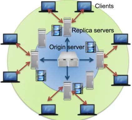
CDN consists of two types of servers as show in Fig. 2.3: origin server and replica server. The original data is stored in the origin server and then it is replicated to the replica servers, which are geographically distributed. Consequently, the data is geographically distributed. A user request to retrieve the data is redirected to the nearest replica server, then the user obtains the data from the nearest replica server. The distance between a user and the server is reduced and the download speed is improved. There are other two advantages in CDN system. One is decreasing in the load of the origin servers because the most of user requests is resolved at the replica servers. The other advantage is fault tolerance. In the single server model, the server is single point of failure. On the other hand, when a replica server has failure, a user request can be redirected to another replica server. The most famous CDN service is Akamai [15].
2.2 Previous works
2.2.1 Routing and Wavelength Assignment (RWA)
One of common issues in all optical wavelength routed networks is routing and wave- length assignment (RWA) problem. We have to determine what path and wavelength will be used. This is because lightpath establishment is required before starting communica- tion in all optical wavelength routed networks. Wavelength continuity constraint, which means a lightpath must use the same wavelength on all links along the path, exists in all optical wavelength routed networks. This constraint affects the network performance such as the blocking probability. As a result, RWA is the most important issue there.
Origin server!
Replica servers! Clients!
Figure 2.3: Origin server and replica servers in CDN
Figure 2.4 overviews the researches on RWA. First of all, RWA is NP-complete prob- lem, consequently, heuristic approaches have been widely studied. The typical sequence of RWA is 1) Calculating a path, which a lightpath will go through, and then 2) Selecting a wavelength, which a lightpath will use on the calculated path. However, there are some approaches that a path and a wavelength are calculated at the same time. Some researches focused on routing, the other focused on wavelength assignment. In addition, researches on RWA can be classified in terms of targeted optical network architecture. The classifi- cation about the targeted networks is shown in Fig. 2.5. The networks can be classified into networks with and without wavelength converters. Additionally, the networks with wavelength converters can be classified by the limitation in wavelength conversion range;
Network with full range wavelength converters, and network with limited range wave- length converters. Networks with full range wavelength converters are classified in terms
Chapter 2 25
RWA
Mixed approach Sequential approach
Focus on routing
Focus on
wavelength assignment
Figure 2.4: Classification of RWA algorithms
of placement type of wavelength converters. One is sparse wavelength conversion, which is a part of nodes has wavelength converters, and the other is non sparse wavelength con- version. An alternative to the use of wavelength converters with limited range is the use of wavelength converters at selected places in the network [16]. Wavelength converters are high cost device, so reducing them makes wavelength-routed networks more cost ef- fective. In static problems, the difference between networks with no wavelength converter and networks with full range wavelength converters is very limited in the literature [17].
Routing
Routing algorithms are classified into three types; Fixed routing, fixed-alternate rout- ing, and adaptive routing [18, 19]. The computation complexity to determine a path in- creases in this order. On the other hand, the blocking probability decreases in the order since more candidate of paths can be calculated as the complexity of an algorithm is higher.
Fixed routing is the simplest type of routing algorithms. Only one path is determined
Target network of RWA
Without WCs With WCs
Full range WCs Limited range WCs
Sparse Non sparse Sparse Non sparse
WC: Wavelength Converter
Figure 2.5: Classification of the target network of researches on RWA
between a pair of a source and a destination node. It is assumed that a link cost is set on each link. Then, the smallest cost path between every pair of two nodes is calculated with the shortest path algorithm, such as Dijkstra’s algorithm, beforehand. When a connection request arrives, the corresponding path is used as a path. The number of hops or the distance of a link is usually used as link cost. The advantage of fixed routing is that the delay time of path set up is small since path selection is static and all of paths can be calculated before a connection request arrives. On the other hand, the disadvantage of fixed routing is inflexibility. The blocking probability is going to high when many paths go through a specific link due to the topology or non uniform traffic. In addition, a path cannot be changed when a failure occurs. Shortest path routing, where the number of hops is used as link cost, is a popular fixed routing.
Fixed-alternate routing is an approach to routing that considers multiple routes. In fixed-alternate routing, each node in the network is required to maintain routing table
Chapter 2 27 that contains an ordered list of number of fixed routes to each destination node. For example, the shortest path, the second shortest path, and the third shortest path may be included. When a connection request arrives, the source node tries to find an available path from the routing table sequentially. The first available path is established. If no available path is found, the connection request is blocked. The blocking probability of fixed-alternate routing is lower than that of fixed routing since a path can be chosen from multiple candidate paths. Fixed-alternate routing provides some degree of fault tolerance upon link failures. However, in fixed-alternate routing, the current network usage is not considered to select a path. As a result, the blocking probability becomes high when the usage of the network greatly fluctuates. ”k-shortest path routing” is a popular fixed- alternate routing. In k-shortest path routing, k paths are stored in the routing table of a node to each destination in ascending order of the number of hops. The available path with minimum hops is established.
In adaptive routing, the path from a source node to a destination node is selected dy- namically, depending on the network state. One form of adaptive routing selects a path from the pre-selected paths like fixed-alternate routing. The other form determined a path from the all of paths from the source node and the destination node dynamically when a connection request arrives. An advantage of adaptive routing is that it achieves lower blocking probability than fixed and fixed-alternate routing since it calculates the most adequate path dynamically. On the other hand, the computational complexity increases compared with fixed and fixed-alternate routing. In addition, extensive support from the control and management protocols to continuously update the current network state infor- mation at the node. One of popular adaptive routing is least-congested path (LCP) routing.
In LCP routing, for each source-destination pair, multiple paths are pre-selected. When a connection request arrives, the least-congested path among the pre-determined paths is chosen. The congestion on a link is measured by the number of wavelength available on