Numerical Analysis of Current Attachment at Thermionic Cathode
for Gas Tungsten Arc at Atmospheric Pressure
†YAMAMOTO Kentaro*, TASHIRO Shinichi** and TANAKA Manabu***
Abstract
In a gas tungsten arc at atmospheric pressure, electrons are emitted from a thermionic cathode of the tungsten electrode, of which the work function would be reduced by generally adding an emitter material such as thorium oxide (ThO2), lanthanum oxide (La2O3), and so on. However, there is still a lack of practical understanding of the physical behavior in the electrode region. For example, current attachment at a thermionic cathode is not yet clear. The present paper presents a methodology for predicting the current attachment at a thermionic cathode for the gas tungsten arc at atmospheric pressure in argon. It is suggested that the current attachment at thermionic cathode is dependent on work function, melting point and the Richardson constant of emitter materials.
KEY WORDS: (Numerical simulation), (Gas tungsten arc), (Cathode)
1. Introduction
In gas tungsten arc at atmospheric pressure, electrons are emitted from a thermionic cathode of the tungsten electrode, of which the work function would be reduced by generally adding an emitter material such as thorium oxide (ThO2), lanthanum oxide (La2O3), and so on 1). However, there is still a lack of practical understanding of the physical behavior in the electrode region. For example, current attachment at thermionic cathode is not yet clear. The emitter materials such as ThO2, La2O3, etc would not only affect work function of the cathode but also current attachment at the cathode. The current attachment at the cathode affects the plasma state of the arc column due to change in the cathode jet induced by the Lorentz force at the cathode region 1, 2). It is well known that arc flames are dependent on the kinds of emitter materials which are added to the tungsten electrode. Welders, for example, suggest that a W-ThO2 electrode produces a hard arc flame but a W-La2O3 electrode produces a soft arc one 3). The present paper presents a methodology for predicting the current attachment at a thermionic cathode for gas tungsten arc at atmospheric pressure in argon. We use a numerical model of a gas tungsten arc where the arc and its electrodes are treated as a unified system.
2. A unified model
The tungsten cathode, arc plasma and anode are described relative to a cylindrical coordinate, assuming rotational symmetry around the arc axis. The calculation domain is shown in Fig. 1. The flow is assumed to be laminar, and the arc plasma is assumed to be in local thermodynamic equilibrium (LTE). The diameter of the tungsten cathode is 3.2 mm with a 60 degrees conical tip. The anode is assumed to be water-cooled copper and its diameter is 50 mm with 10 mm in thickness.
The mass continuity equation is
0 ) ( ) ( 1 ? - z r v r v r r r • t • t •• (1)
the radial momentum conservation equation is
2 2 2 ) ( ) 2 ( 1 ) ( ) ( 1 r v r v z v z r v r r r B j r P v v z v r r r r z r r z r z r j • • j • • j •• • • j •• • • t •• t •• s / -/ / ? - (2)
Transactions of JWRI is published by Joining and Welding Research Institute, Osaka University, Ibaraki, Osaka 567-0047, Japan
† Received on July 10, 2009 * Graduate school student ** Assistant Professor *** Professor
Numerical Analysis of Current Attachment at Thermionic Cathode for Gas Tungsten Arc at Atmospheric Pressure
the axial momentum conservation equation is
) ( 1 ) 2 ( ) ( ) ( 1 2 r v r z v r r r z v z B j z P v z v v r r r z r z r z z r • • j • • j •• • • j •• • • t •• t •• s -/ ? - (3)
the energy conservation equation is
R E j E j z h c z r h c r r r h v z h v r r r z z r r p p z r / -? - ( ) 1 ( ) ( ) ) ( 1 • • m •• • • m •• t •• t •• (4)
the current continuity equation is
0 ) ( ) ( 1 ? - z r j z rj r r • • •• (5) and the Ohm's law (6) is
z z r
r E j E
j ?/u ; ?/u (6) and Maxwell's equation is
1
r
•
•
r
(rB
s)
?
o
0j
z.
(7)where t is time, h is enthalpy, P is pressure, vr and vz are the radial and axial velocities, jr and jz are the radial and axial components of the current density, g is the acceleration due to gravity, m is the thermal conductivity, cp is the specific heat, is the density, is the viscosity, U is the radiation emission coefficient, j is the electrical conductivity, B is the azimuthal magnetic field, 0 is the permeability of free space, Er and Ez are respectively the radial and axial components of the electric field defined by Er =-АV/Аr and Ez=-АV/Аz, where V is electric
potential. Calculations at points on both electrode surfaces would need to include the special process occurring at the surfaces. Thus, additional energy flux terms need to be included in equation (4) at each electrode surface for thermionic heating and cooling from the electrons, ion heating, and radiation cooling. The additional energy flux for the cathode HK and for the anode HA are
Cathode HK = -igT4 -|je| lK + |ji|Vi (8) and
Anode HA = -igT4 +|je| lA (9) respectively. Here i is the surface emissivity, g is the Stefan-Boltzmann constant, lK is the work function of the tungsten cathode, lA is the work function of the anode, Vi is the ionization potential of helium, je is the electron
current density, and ji is the ion current density. We calculate the electron saturation current density at the cathode surface by thermionic emission of electrons jR from the Richardson-Dushman equation. The ion current density ji is then assumed to be |j|< |jR| if |j| is greater than |jR| ; where |j|=| je|+|ji| is the total current density at the cathode surface obtained from equation. The detailed boundary conditions and numerical method are given in our previous paper 4). Within both electrodes, we set vr=vz=0. The temperatures at boundaries CD, DE, EF, and FA in Fig. 1 are taken to be the same room temperature, namely, 300 K. The electric potential is set to zero at the base of the anode, CD, in Fig.1. In order to avoid the problem that the equilibrium electrical conductivity is effectively zero in the plasma close to the electrodes owing to the low plasma temperature, we employ an LTE-diffusion approximation 5). The differential equations (1) to (7) are solved iteratively by the SIMPLEC numerical procedure 6) for the whole region of the arc welding process.
Anode 0 5 10 15 20 25 Radial distance (mm) A x ial di st an c e ( m m ) 0 -5 -10 -15 -20 -25 -30 10 5 15 r z Tungsten cathode (1.6 mm) Arc plasma B E D C F A Anode
Fig. 1 Schematic illustration of simulation domain. 3. Treatment of current attachment
The in-situ measurements of work function of a cathode in the argon gas tungsten arc during operation at atmospheric pressure were carried out simultaneously with measurements of surface temperature of the cathode 7)
. This technique was based on the photoelectric effect at the surface of the tungsten cathode with the use of a pulse laser system. The effective work functions of pure W, W-2% ThO2 and W-2% La2O3 electrodes during operation at a current of 200 A were 4.6 eV, 2.8 eV and 3.0 eV from the in-situ measurements. These results were very close to the work functions of W, ThO2 and La2O3
as pure materials obtained from the literature 8). Therefore, it was concluded that the effective work function of tungsten electrodes adding an emitter material, namely, ThO2 or La2O3, was dominated by the work function of the emitter material even though its addition to the electrode was only 2% in weight. From our previous study 7), we have our image of current attachment at thermionic cathode, as follows. (a) Emitter material plays a role of thermionic emission of electrons due to its lower work function independently of its conditions, namely, solid or liquid. (b) Tungsten weakly contributes to thermionic emission of electrons due to its higher work function. (c) Emitter material below its melting point is scattered on the surface of tungsten, as shown in Fig. 2. A size of an emitter material is around 5 m 1). The emitter material practically covers about 5% of the tungsten surface because 2 wt% of ThO2 and La2O3 becomes 4 to 6 vol% of ThO2 and La2O3. (d) Emitter material above its melting point covers the whole surface of tungsten. In order to evaluate the current attachment, the space-charge sheath at the cathode surface has to be regularly calculated with thermionic emission of electrons 9, 10). However, our unified model does not take the sheath into account. Therefore, for simplification, we assume that the role of thermionic emission of electrons by emitter material is replaced with the electrical conductivity of arc plasma on the cathode surface, as shown in Fig. 3. If surface temperature of the cathode is higher than the melting point of the emitter material, the electrical conductivity of the arc plasma on the cathode surface is assumed to be a regular value independently of temperature because the emitter material covers the whole surface of tungsten. If surface temperature of the cathode is o the contrary lower than the melting point of the emitter material, the electrical conductivity of arc plasma in one mesh neighboring on the cathode surface is assumed to be 5% of the regular value because the emitter material practically covers about 5% of the tungsten surface. The flux of arc current from one mesh to another mesh is roughly represented by I = S(j E), where S is the area between two meshes. We assume to replace 5%S by 5%j.
Three types of tungsten electrode, namely, W-2% ThO2, W-2% La2O3 and W-2% CeO2 are calculated in this paper. The numerical values given to a unified model are tabulated in Table 1. These values are from the literature 8). In the manufacturing process of a tungsten electrode, CeO2 is reduced to Ce2O3 after sintering in pure hydrogen atmosphere 11), and then we also assume that the whole CeO2 of W-2% CeO2 electrode is changed to Ce2O3 in this paper.
Above the melting point of emitter material Below the melting point of emitter material
Emitter material covers the whole su rface of W Emitter material is scattered on the surface of W
Fig. 2 An image of current attachment.
Arc plasma W electrode
u
au
au
au
au
wu
wu
wu
wu
wu
w u: Electrical conductivityT<T
mT>T
mTm: Melting point of emitter material
7'"
u
a7'"
u
aFig. 3 Treatment of current attachment for a unified arc electrode model.
Numerical Analysis of Current Attachment at Thermionic Cathode for Gas Tungsten Arc at Atmospheric Pressure
4. Results and discussion
Figure 4 shows two-dimensional temperatures and fluid flow velocities of gas tungsten arcs for various kinds of electrodes at 200 A of arc current and 5 mm of arc length. These calculations were made for the steady state. The difference between calculated arc voltages for various electrodes is negligible and the value of the arc voltage is about 11.2 V. This tendency was pointed out by experiments 1). However, the plasma state of the arc column is locally affected by the electrode types. Specifically, the maximum temperature of arc plasma close to the cathode tip for W-2% ThO2 reaches 19,000 K and it is the highest value in comparison with the other temperatures for W-2% La2O3 and W-2% CeO2, because the current attachment at the cathode tip is constricted by a centralized limitation of liquid area of ThO2 due to its higher melting point. This higher temperature of the plasma close to the cathode tip at the arc axis would play an important role in the production of a hard arc flame. In cases of W-2% La2O3 and W-2% CeO2, the liquid areas of La2O3 and Ce2O3 are widely expanded at the cathode tip due to their lower melting points and then produce uniform current attachments at the cathode, resulting a soft arc flame.
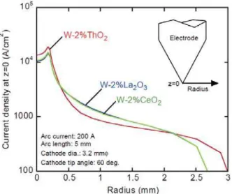
Figure 5 shows temperature distributions at electrode surfaces. The maximum temperatures at the tip are 3776 K, 3620 K and 3210 K for W-2% ThO2, W-2% CeO2 and W-2% La2O3, respectively. These are good agreement with experimental results reported by Haidar and Farmer 12). The tip temperature of W-2% La2O3 during operation is clearly lower than that of W-2% CeO2 although both work functions of La2O3 and Ce2O3 are almost the same as shown in Table 1. This reason is deduced from a difference of the Richardson constant between 96.0 A/cm2K2 in La2O3 and 30.0 A/cm2K2 in Ce2O3. Figure 6 shows arc pressure distributions at the anode surface. The maximum arc pressure for W-2% CeO2 reaches 395 Pa and then it is similar to 391 Pa for W-2% La2O3. However, the maximum arc pressure for W-2% ThO2 is clearly lower than these. Sadek measured arc pressure distributions at a water-cooled copper anode by a semiconductor transducer, as shown in Fig. 7 1). Since he, unfortunately, employed 45 degree for the conical tip angle of tungsten electrode and 3 mm for the arc length, we can not compare both results of experiment and calculation directly. However, his experimental results show that the maximum arc pressures of W-2% CeO2 and W-2% La2O3 are almost the same but that for W-2% ThO2 is clearly lower than these. This tendency is very similar to the tendency given by calculations as shown in Fig. 6, although the absolute values of arc pressure in both cases are different due to differences of a few conditions as stated above. Figure 8 shows current density distributions at 0 mm of axial distance in Fig. 1. The maximum current density for W-2% ThO2 is the highest in comparison with those for W-2% La2O3 and W-2% CeO2. However, the current density for W-2% ThO2 drastically decreases toward the radius and then it is lower than those for W-2% La2O3 and W-2% CeO2 at
around 0.5 mm to 2 mm in the radius. This characteristic of current density distribution for W-2% ThO2 locally leads to the highest values in the tip temperature of the cathode, in the temperature of the arc plasma and in the fluid flow velocity of the cathode jet, but it produces the lowest value of the arc pressure at the anode surface because an average momentum of the cathode jet for W-2% ThO2 is smaller than those for the other two electrodes due to more uniform current density distributions for W-2% La2O3 and W-2% CeO2 than that for W-2% ThO2, as shown in Fig. 8. From the above results, it can be concluded that the current attachment at thermionic cathode for gas tungsten arc at atmospheric pressure is dependent on work function, melting point and the Richardson constant of emitter materials.
Fig. 4 Temperatures and fluid flow velocities of gas tungsten arcs for various types of electrode.
Fig. 6 Arc pressures at anode surface.
Fig. 7 Experimental results of arc pressure at anode surface 1).
Fig. 8 Current density distributions at the tip of tungsten electrode.
4. Conclusions
The conclusions of this study are summarized as follows.
(1) Study of the current attachment at the thermionic cathode for a gas tungsten arc at atmospheric pressure was examined from numerical calculations of an arc-electrode unified model.
(2) It is suggested that the current attachment at the thermionic cathode was dependent on work function, melting point and the Richardson constant of emitter materials.
(3) The maximum temperature of arc plasma close to the cathode tip for W-2% ThO2 reached 19,000 K and it was the highest value in comparison with the other temperatures for W-2% La2O3 and W-2% CeO2, because the current attachment at the cathode tip was constricted by a centralized limitation of liquid area of ThO2 due to its higher melting point. This higher temperature of plasma close to the cathode tip at the arc axis would play an important role in production of a hard arc flame. (4) In the cases of W-2% La2O3 and W-2% CeO2, the liquid areas of La2O3 and Ce2O3 were widely expanded at the cathode tip due to their lower melting points and which then produce uniform current attachments at the cathode, resulting a soft arc flame.
(5) The tip temperature of W-2% La2O3 during operation was clearly lower than that of W-2% CeO2 although both work functions of La2O3 and Ce2O3 were almost the same. This reason was deduced from a difference of the Richardson constant between 96.0 A/cm2K2 in La2O3 and 30.0 A/cm2K2 in Ce2O3.
References
1) Sadek AA, Ushio M and Matsuda M; Metall. Trans. A, 1990; 21 A: p3221-3236.
2) Tanaka M et. al.; Plasma Chem. & Plasma Process., 2003; 23: p585-606.
3) Mita T; private communication, 2006.
4) Tanaka M, Ushio M and Lowke JJ; JSME Int. J., Series B, 2005; 48: p.397-404.
5) Lowke JJ and Tanaka M; J. Phys. D: Appl. Phys., 2006; 39: p.3634-3643.
6) Patanker SV; Numerical Heat Transfer and Fluid Flow, Hemisphere Publishing Corporation, 1980.
7) Tanaka M et. al.; J. Phys. D: Appl. Phys., 2005; 38: p.29-35. 8) Fomenko VS: Emission Properties of Materials, Kiev,
Naukova Dumka, 1970.
9) Morrow RR and Lowke JJ; J. Phys. D: Appl. Phys., 1993; 26: pp.634-642.
10) Ushio M et. al.; J. Phys. D: Appl. Phys., 1994; 27: p.561-566.
11) Ushio M et.al.; Plasma Chem. & Plasma Process., 1991; 11: p.81-101.
12) Haidar J and Farmer AJD; J. Phys. D: Appl. Phys., 1995; 28: p.2089-2094.
Transactions of JWRI, Vol.38 (2009), No. 1
Terahertz Wave Resonance Profiles in Micro Patterns of Dielectric
Tablets Fabricated by Using Stereolithography of Structural
Joining Process
†KIRIHARA Soshu*, HOTTA Mikinori*, NIKI Toshiki** and OHTA Noritoshi**
Abstract
Materials tectonics is new concept to control energy flows form environmental field to human beings through spatial patterns of ceramics or metals fabricated by using structural joinings. Recently, we have developed two dimensional micro patterns composed of dielectric ceramics in order to control terahertz waves effectively by using stereolithography. In this process, photosensitive resin pastes with titania particles dispersion were spread on a glass substrate with 10 μm in layer thickness by moving a knife edge, and two-dimensional images of ultra violet rays were exposed by using a digital micro-mirror device with 2 μm in part accuracy. Through the layer by layer stacking, periodic structures composed of micro polygon tablets were formed. Dielectric constant of these tablets was measured as 40. Subsequently, the electromagnetic wave properties of these samples were measured by using a terahertz spectroscopic device. In transmission spectra, forbidden bands were observed form 0.33 to 0.57 THz through electromagnetic wave diffractions. Moreover, a localized mode of a transmission peaks was formed in the band gap frequency range. Through transmission line modeling simulations at the peak frequency, electromagnetic energies were concentrated strongly into the thin micro patterns. The terahertz waves are well known to resonate with various types of protein molecules, and expected to control the biological material syntheses through the frequency excitements. Fabricated dielectric ceramic micro patterns are considered to be applied for the new types of reactors to create the useful materials as artificial interfaces between the electromagnetic energy and the biological materials.
KEY WORDS: (Dielectric Micro Pattern) (Band Gap) (Micro-Stereolithography) (Terahertz Wave)
1. Introduction
In near future industries, electromagnetic waves in a terahertz frequency range with micrometer order wavelength will be expected to apply for various types of novel sensors which can detect gun powders, drugs, bacteria in foods, micro cracks in electric devices, cancer cells in human skin and other physical, chemical and living events 1-6. In our group, micro-stereolithography of a computer-aided design and manufacturing (CAD/CAM) system was newly developed to realize a spatially structural joining of ceramic or metal components in micro- meter orders to control the terahertz wave effectively 7-12. By using this system, diamond type photonic crystals with periodic arrangements of micrometer order dielectric lattices were fabricated successfully to exhibit forbidden gaps through Bragg diffraction in the terahertz wave frequency rages 13-20. Moreover, the spatial propagations of the electromagnetic waves were controlled effectively by using the the modified photonic crystals with twinned diamond lattices
20-24
. The incident electromagnetic wave was resonated and localized in a plane defect interface through multiple reflections between the twinned mirror-symmetric diffraction lattices, and a plane wave radiation of the terahertz wave beam emission was realized. In this investigation, two dimensional periodic patterns composed of acrylic resins with nano-sized titania particles dispersions were fabricated by using the micro-stereolithography to realize the wave diffractions and resonations in the terahertz frequencies. Filtering effects of the electromagnetic waves for a perpendicular direction to the dielectric patterns were observed through time domain spectroscopic measurements. These micro geometric patterns of extremely thin devices with a high dielectric constant were designed to concentrate the electromagnetic energies effectively through a theoretical simulation method.
2. Experimental Procedure
The micro dielectric pattern was designed as the periodic structure composed of micro square tablets of † Received on July 10, 2009
* Associate Professor
** Specially Appointed Researcher *** Graduate Student
Transactions of JWRI is published by Joining and Welding Research Institute, Osaka University, Ibaraki, Osaka 567-0047, Japan
240×240×100 μm in dimensions at intervals of 45 μm. These micro tablets of 9×9=81 in numbers were arranged to form the extremely thin dielectric device of 2520×2520×100 μm in whole dimensions. The real sample was fabricated trough the micro-stereo- lithographic system. A designed graphic model was converted for stereolithography (STL) data files and sliced into a series of two dimensional layers. These numerical data were transferred into the fabrication equipment (D-MEC: SIC-1000). Figure 1 shows a schematic illustration of the fabrication system. As the raw material, nanometer sized titania particles of 270 nm in average diameter were dispersed into a photo sensitive acrylic resin at 40 volume percent. The mixed slurry was squeezed on a working stage from a dispenser nozzle. This material paste was spread uniformly by a moving knife edge. Layer thickness was controlled to 5 μm. Ultra violet lay of 405 nm in wavelength was exposed on the resin surface according to the computer operation. Two dimensional solid patterns were obtained by a light induced photo polymerization. High resolutions in these micro patterns had been achieved by using a digital micro-mirror device (DMD). In this optical device, square aluminum mirrors of 14 m in edge length were assembled with 1024×768 in numbers. Each micro mirror can be tilted independently, and cross sectional patterns were dynamically exposed through objective lenses as bitmap images of 2 m in space resolution. After stacking and joining these layers through photo solidifications, the periodical arrangements of the micro dielectric tablets were obtained. A bulk sample of the titania dispersed acrylic resin with the same material composition was also fabricated to measure the dielectric constant of the
composite tablets. A terahertz wave attenuation of transmission amplitudes through the micro pattern were measured by using a terahertz time domain spectrometer (TDS) apparatus (Advanced Infrared Spectroscopy: Pulse-IRS 1000). Figure 2 shows the schematic illustration of the measurement system. Femto-second laser beams were irradiated into a micro emission antenna formed on a semiconductor substrate to generate the terahertz wave pulses. The terahertz waves were transmitted trough the micro patterned samples perpendicularly. The dielectric constant of the bulk samples were measured through a phase shift counting. Diffraction and resonation behaviors in the dielectric pattern were calculated theoretically by using a transmission line modeling (TLM) simulator (Flomerics: Micro- stripes Ver. 7.5) of a finite difference time domain (FDTD) method.
3. Results and Discussion
The dielectric micro patterns with the periodic arrangement of the acrylic tablets with the titania particles dispersion was fabricated successfully by using the micro-stereolithography system as shown in Fig. 3. Dimensional accuracies of the fabricated micro tablets and the air gaps were approximately 0.5 percent in length. The nanometer sized titania particles were verified to disperse uniformly in the acrylic resin matrix as shown in
Fig. 4 thorough a scanning electron microscope (SEM)
observation. The dielectric constant of the composite material of the titania dispersed acrylic resin was measured as 40. Figure 5-(a) and (b) show transmission spectra measured and simulated by using the TDS and TLM methods, respectively. The measured result has
Transactions of JWRI, Vol.38 (2009), No. 1
good agreement with the calculated one. Opaque regions were formed in both spectra form 0.33 to 0.57 THz approximately. Maximum attenuation was measured as about -20 dB in transmission amplitude, and the minimum transmittance showed below 1 percent. The two dimensional photonic crystals with periodic arrangement with the lower dielectric contrasts were well known to open the band gaps limitedly for the parallel directions to the plane structures. However, the micro
patterns with the periodically arranged square tablets above 30 in dielectric constant could exhibit the clear forbidden bands in the transmission spectra toward the perpendicular direction to the plane patterns through the theoretical simulations. The fabricated dielectric pattern is considered to totally reflect the terahertz wave at the wavelength comparable to the optical thickness as schematically illustrated in Fig. 6. Two different standing waves vibrating in the air and the dielectric regions form
the higher and the lower edges of the band gap. The gap width can be controlled by varying geometric profile, filling ratio, and the dielectric constant of the tablets. As shown in Fig. 5, the localized mode of a transmission peak was observed at 0.47 THz in the band gap. Figure 7 shows a simulated distribution of electric field intensities in the micro pattern at the localized frequency. The white area indicates that the electric field intensity is high, whereas the black area indicates it is low. The incident terahertz wave is resonate and localized along the two dimensionally arranged dielectric tablets at the specific frequency. The amplified terahertz wave can transmit through the micro pattern. Therefore, the transmission peak of the localized mode should be formed clearly in the photonic band gap frequency range.
4. Conclusions
Micro square tablets of acrylic resin with titania particles dispersions were arranged periodically in two dimensions by using a stereolithography system of a finely joining process. Fabricated micro pattern was verified to be able to exhibit a forbidden band of opaque region. A localized mode of a transmission peak was clearly formed at a specific frequency to concentrate
electromagnetic energies in the periodic arrangement of the dielectric constant. The terahertz waves are well known to resonate with various types of protein molecules, and expected to control the biological material syntheses by using frequency excitements through characteristic resonation effects. The fabricated micro pattern can include various types of solutions into their air gaps between the square tablets, therefore, it will be applied for novel micro reactors to create useful biological materials.
Acknowledgments
This study was supported by Priority Assistance for the Formation of Worldwide Renowned Centers of Research - The Global COE Program (Project: Center of Excellence for Advanced Structural and Functional Materials Design) from the Ministry of Education, Culture, Sports, Science and Technology (MEXT), Japan.
References
1) Martin Van Exter, Ch. Fattinger, and D.
Grischkowsky: Terahertz Time-domain Spectroscopy of Water Vapor”, Optics Letters Vol. 14, Iss. 20, pp. 1128-1130, October, 1989.
2) Daniel Clery, “Brainstorming Their Way to an Imaging Revolution”, Science, Vol. 297, pp. 761-
Transactions of JWRI, Vol.38 (2009), No. 1
763, August, 2002.
3) Kodo Kawase, Yuichi Ogawa, Yuuki Watanabe, and Hiroyuki Inoue, “Non-destructive Terahertz Imaging of Illicit Drugs Using Spectral Fingerprints”, Optics Express, Vol. 11, Iss. 20, pp. 2549-2554, October, 2003.
4) R. M. Woodward, V. P. Wallace, D. D. Arnone, E. H. Linfield, and M. Pepper, “Terahertz Pulsed Imaging of Skin Cancer in the Time and Frequency Domain”, Journal of Biological Physics, Vol. 29, No. 2-3, pp. 257-259, June, 2003.
5) V. P. Wallace, A. J. Fitzgerald, S. Shankar, N. Flanagan, “Terahertz Pulsed Imaging of Basal Cell Carcinoma ex Vivo and in Vivo”, The British Journal of Dermatology, Vol. 151, No. 2, pp. 424–432, August, 2004.
6) Yutaka Oyama, Li Zhen, Tadao Tanabe, and Munehito Kagaya, “Sub-Terahertz Imaging of Defects in Building Blocks”, NDT&E International, Vol. 42, No. 1, pp. 28-33, January, 2008. 7) Weiwu Chen, Soshu Kirihara, and Yoshinari
Miyamoto, “Fabrication and Measurement of Micro Three- Dimensional Photonic Crystals of SiO2 Ceramic for Terahertz Wave Applications”, Joiurnal of the American Ceramic Society, Vol. 90, No. 7, pp. 2078-2081, July, 2007.
8) Weiwu Chen, Soshu Kirihara, and Yoshinari Miyamoto, “Three-dimensional Microphotonic Crystals of ZrO2 Toughened Al2O3 for Terahertz wave applications”, Applied Physics Letter , Vol. 91, No. 15, 153507-1-3, October, 2007.
9) Weiwu Chen, Soshu Kirihara, and Yoshinari
Miyamoto, “Fabrication of Three-Dimensional Micro Photonic Crystals of Resin-Incorporating TiO2 Particles and their Terahertz Wave Properties”, Journal of the American Ceramic Society, Vol. 90, No. 1, pp. 92-96, January, 2007.
10) Weiwu Chen, Soshu Kirihara, Yoshinari Miyamoto, “Static Tuning Band Gaps of Three-dimensional Photonic Crystals in Subterahertz Frequencies”, Applied Physics Letters, Vol. 92, pp. 183504-1-3, May, 2008.
11) Hideaki Kanaoka, Soshu Kirihara, and Yoshinari Miyamoto “Terahertz Wave Properties of Alumina Microphotonic Crystals with a Diamond Structure”, Journal of Materials Research Vol. 23, No. 4, pp. 1036-1041, April, 2008.
12) Yoshinari Miyamoto, Hideaki Kanaoka, Soshu Kirihara “Terahertz Wave Localization at a Three-dimensional Ceramic Fractal Cavity in Photonic Crystals”, Journal of Applied Physics, Vol. 103, pp. 103106-1-5, May, 2008.
13) Eli Yablonovitch: Inhabited Spontaneous Emission in Solid-state Physics and Electronics”, Physical Review Letter, Vol. 58, No. 20, pp. 2059-2062, May, 1987.
14)Sajeev John, “Strong Localization of Photons in Certain Disordered Dielectric Superlattices”, Physical Review Letter, Vol. 58, No. 23, pp. 2486-2489, June, 1987.
15)K. M. Ho, C. T. Chan, and C. M. Soukoulis, “Existence of a Photonic Gap in Periodic Dielectric Structures”, Physical Review Letter”, Vol. 65, No. 25, pp. 3152-3165, December, 1990.
16)B. Temelkuran, Mehmet Bayindir, E. Ozbay, R. Biswas, M. M. Sigalas, G. Tuttle, and K. M. Ho, “Photonic Crystal-based Resonant Antenna with Very High Directivity”, Journal of Applied Physics, Vol. 87, No. 1, pp. 603-605, January, 2000.
17)Soshu Kirihara, Yoshinari. Miyamoto, Katsuhiro Takenaga, Mitsuo Wada Takeda, and Kenji
Kajiyama, “Fabrication of Electromagnetic Crystals with a Complete Diamond Structure by
Stereolithography”, Solid State Communications, Vol. 121, No. 8, pp. 435-439, March, 2002. 18)Soshu Kirihara, Mitsuo Wada Takeda, Kazuaki
Sakoda, and Yoshinari Miyamoto, “Control of Microwave Emission from Electromagnetic Crystals by Lattice Modifications”, Solid State
Communications, Vol. 124, No. 4, pp. 135-139, October, 2002.
19)Shingo Kanehira, Soshu Kirihara, and Yoshinari Miyamoto, “Fabrication of TiO2-SiO2 Photonic Crystals with Diamond Structure”, Journal of the American Ceramic Society, Vol. 88, No. 6, pp. 1461-1464, June, 2005.
20)Hitomichi Takano, Bong-Shik Song, Takashi Asano, and Susumu Noda, “Highly Efficient in-Plane Channel Drop Filter in a Two-Dimensional Heterophotonic Crystal”, Applied Physics Letters, Vol. 86, No. 24, pp. 241101-1-3, June, 2005. 21)Soshu Kirihara and Yoshinari Miyamoto: “Terahertz
Wave Control Using Ceramic Photonic Crystals with Diamond Structure Including Plane Defects
Fabricated by Micro-stereolithography”, The
International Journal of Applied Ceramic Technology, Vol. 6, No. 1, pp. 41-44 January, 2009.
22)Soshu Kirihara, Toshiki Niki, and Masaru Kaneko, “Terahertz Wave Behaviors in Ceramic and Metal Structures Fabricated by Spatial Joining of Micro- stereolithography, Journal of Physics, in printing. 23)Soshu Kirihara, Toshiki Niki, Masaru Kaneko:
“Three-dimensional Material Tectonics for Electromagnetic Wave Control by Using Micoro- stereolithography”, Ferroelectrics, in printing. 24)Soshu Kirihara, Kota Tsutsumi, Yoshinari
Miyamoto: “Localization Behavior of Microwaves in Three-dimensional Menger Sponge Fractals
Fabricated from Metallodielectric Cu/polyester Media”, Science of Advanced Materials, in printing.
Titanium Matrix Composite Reinforced with In-situ Formed TiC
Using Carbon Black Nano Particles via a Wet Process
†THRERUJIRAPAPONG Thotsaphon*, KONDOH Katsuyoshi**, IMAI Hisashi***, UMEDA Junko*** and FUGETSU Bunshi****
Abstract
Powder metallurgy (P/M) titanium matrix composite (TMC) reinforced with carbon black particles was produced by spark plasma sintering (SPS) and the hot extrusion process. Carbon black particles were added for the in –situ formation of TiC dispersoids in the SPS process. Two kinds of titanium (Ti) powders, sponge and fine Ti, were coated with carbon black particles via a wet process using the zwitterionic solution containing carbon black particles. The distribution of the particles on the Ti powder surface before the consolidation process was observed by scanning electron microscopy (SEM). The morphology and distribution of in-situ TiC phases were investigated by optical microscope and SEM equipped with an EDS analyzer. The mechanical properties of extruded pure Ti composites reinforced with in-situ formed TiC particles were evaluated. The mechanical properties of these composites were remarkably improved by adding a small amount of carbon black from 0.07 ~ 0.16wt.%. Finally, the fractured surfaces of TMC specimens after the tensile test were observed.
KEY WORDS: (Titanium) (Carbon black) (Spark plasma sintering) (Hot compression) (Titanium carbide)
1. Introduction
Titanium and titanium alloys have been drawn interest because they are high specific strength materials and widely used in various industrial applications such as aerospace sectors1). This report shows a simple production method for high strength titanium matrix composites. High strength Ti-based alloys and composites have been fabricated via hot working2), ball milling3-4) and severe plastic deformation5-6) processes but those methods remain the obstacles in the industrial approach, such as the limitation of time, energy consumption, production capability. It has been far from mass production. Recently, Ti reinforced with un-bundled carbon nanotubes (CNTs) via a powder metallurgy route was introduced7-8). One of the researchers in the previous study showed the effective preparation of un-bundled CNTs by using zwitterionic surfactant solutions via a wet process9). Zwitterionic surfactant, 3-(N,N-dimethylstearylammonio) propanesul- fonate, was used in this study. The electrostatic interaction between positive and negative charges of
hydrophilic groups is attracted together, while the neutral charge of the hydrophobic group is attracted to the surface of carbon nanotubes. The successful application of the above wet process on pure titanium reinforced with multi-wall carbon nanotubes are described elsewhere7-8). By using the same mechanism, the uniform distribution of nano-particulates by the typical linear zwitterionic surfactant solution is applied to carbon black nano-particles. In the present study, the commercially pure titanium powders coated with non-agglomerated carbon black particles were prepared by the wet process, and consolidated by SPS and hot extrusion as wrought composites. It was concluded that the application of the wet process to carbon black nano-particles conferred superior mechanical properties for P/M titanium matrix composites reinforced with in-situ formed TiC dispersoids.
2. Experimental
Two kinds of commercially pure Ti powder, sponge and atomized Ti powders, having a mean particle sizes of † Received on July 10, 2009
* Graduate Student ** Professor
*** Specially Appointed Researcher
**** Professor, Hokkaido University
Transactions of JWRI is published by Joining and Welding Research Institute of Osaka University, Ibaraki, Osaka 567-0047, Japan.
686 m and 30 m, were used as the starting materials, respectively. The chemical compositions of the starting materials are shown in Table 1. Carbon black (CB) particles with an average diameter of 290 nm were used as the reinforcement. This is because CB particles are very cheap materials compared to carbon nanotubes, and useful for synthesizing titanium carbide (TiC) particles via the SHS process10). A typical linear zwitterionic surfactant solution with carbon black concentration of 0.5 wt.% was prepared. Ti powders were immersed into the aqueous carbon black/zwitterionic solution, and subsequently dried in an oven at 373 K for 10.8 ks. Ti powders coated with carbon black particles were obtain. The solid surfactants also exist on the Ti surface, and should be eliminated before the consolidation process because they changed to gases at elevated temperature over 773K 11), creating pore defects in bulk consolidated materials. To eliminate the solid zwitterionic substance, the coated Ti powders were heated again in a horizontal tube furnace at 873 K for 3.6 ks under an Ar gas atmosphere. The composite Ti powders with CB particles were consolidated by a spark plasma sintering (SPS, Syntech Co. SPS-103S) process at 1073 K for 1.8 ks under vacuum atmosphere. The applied load during the process was 30 MPa. The sintered Ti billet was heated to 1273 K for 180 s under an Ar atmosphere, and immediately transferred to the hot extrusion process. The extrusion ratio, speed and die temperature were 37, 3.0 mm/s and 673 K, respectively. Microstructure and phase characterization of extruded Ti composites were investigated by X-ray diffraction (XRD, Shimadzu XRD-6100), optical microscope and scanning electron microscope equipped with an energy dispersive spectrometry (SEM-EDS, JOEL, JSM-6500F). The extruded Ti composite materials were machined to tensile specimen bars with 3.0mm-diameter and 20mm-gauge length. The mechanical properties were evaluated by universal test machine (Autograph AG-X 50kN, Shimadzu) under a strain rate of 5 ×10⁻⁴ /s. Hardness was measured by a micro-Vickers hardness tester (Mitutoyo). The fractured surfaces of tensile specimens were observed by SEM.
3. Results and Discussion
Figure 1 shows SEM photo showing the appearance of carbon black particles used as raw materials in this experiment. The irregular shape carbon black particles have an average size of 290 nm. They consist of the agglomerated primary particles, having a mean size of 100 nm or less. Figure 2 shows the appearance of Ti powders coated with CB particles. The local surface of Ti powders was covered with CB particles because the concentration of CB was 0.5wt.% and not enough to fabricate the completely coated Ti/CB composite powders. The solid surfactants also existed on the Ti surfaces, shown by arrows, and should be eliminated before consolidation process. Most of the CB particles are locally deposited on the curve of powders.
After elimination of the solid zwitterionic substance at 873 K for 3.6 ks, the Ti powders had partially reacted with CB to form TiC at the interface as shown in Fig.3, which is consistent with theoretical thermodynamics and experimental data 12-15).
X-ray diffraction patterns of the extruded Ti composite materials reinforced with in-situ formed TiC composite are shown in Fig.4. The first peaks of TiC at 2 = 35.74 and 36.04 deg. are detected in both extruded sponge and fine Ti/CB samples. The second peak is, however, detected at 41.72 deg. for fine Ti sample only. The relative intensity and the breadth of the TiC peak of extruded fine Ti/TiC composite obviously indicated that the volume fraction and size of TiC particles have very small existences in the matrix. TiO2 peaks could not be detected in this study which means the oxidation does not occur inside the extruded materials during hot extrusion process, and does not affect the mechanical properties.
Fig.1 SEM image of the carbon black particles used in this experiment.
Fig.2 Ti powder coated with carbon black particles via a wet process.
Solid surfactant
Microstructures of extruded Ti/CB composites are shown in Fig.5. TiC particles are uniformly distributed in the matrix as shown in Fig. 5 (a) and (c), which explains the high distribution of CB particles on Ti powder surface by the wet process. The particle size measurement of both sponge and fine extruded Ti/CB composites indicates that the size of in-situ formed TiC is 1.8 and 3.0 m, respectively. The grain size measurement of extruded Ti composites with CB and without CB reinforcement indicates the grain size in the range of 4 to 7 m. The grain size of all extruded samples has not significant difference between them. Therefore, the effect of grain size on mechanical properties will be the same level, and does not show an important role higher than those of in-situ TiC
dispersiods. An average grain size and TiC particle size of all extruded samples are summarized in Table 2.
The tensile test results are shown in Fig.6, revealing stress – strain curves, and summarized in Table 2. Tensile properties of extruded Ti without CB prepared in this study are almost same as those of the conventional pure Ti 16-17). The average yield stress (YS) and tensile strength (TS) values of extruded sponge and fine Ti/TiC composites are 317, 479, 744 and 878 MPa, respectively. In the case of sponge Ti powders, the increment of YS and TS by adding CB particles are 28.3% and 16.2%, respectively. In the case of extruded fine Ti/TiC composite, YS and TS are significantly increased 64.2% and 35.7%, respectively. The increasing percentage of YS and TS of sponge Ti composite is due to the increment of carbon content, which is increased from 0.01 to 0.073 and 0.162wt.% for sponge and fine Ti, respectively.
The dispersion of in-situ formed TiC particles in the matrix caused an enhancement of mechanical properties of Ti/TiC composites. Elongation percentage of the extruded sponge and fine Ti/TiC composite is decreased 7.87% and 21.45%, compared with the extruded pure Ti composite with no reinforcement.
Table 1 Ti powder coated with carbon black particles via a wet process.
Materials Fe Cl Mg Si N C O Ti
Sponge Ti 0.01 0.07 0.03 <0.01 <0.01 0.01 0.069 Bal.
Fine Ti 0.03 <0.002 <0.001 0.01 0.02 <0.01 0.21 Bal.
Fig.3 Partial bonding of Ti/carbon black after annealing at 873K for 3.6 ks
30 35 40 45 50 55 60 65 70 75 80 Diffraction angle 2 , deg.
砧Ti 棋TiC 棋 砧 砧 砧 砧 砧 砧 砧 砧 棋 (a) (b) 棋 30 35 40 45 50 55 60 65 70 75 80 Diffraction angle 2 , deg.
砧Ti 棋TiC 棋 砧 砧 砧 砧 砧 砧 砧 砧 棋 (a) (b) 棋
Fig.4 XRD patterns of extruded sponge (a) and extruded fine Ti composites (b) with in-situ formed TiC
Before etch After etch
Fig.5 Optical microstructures of P/M extruded titanium composite reinforced with TiC dispersoids using sponge Ti/carbon black (a)-(b) and fine Ti/carbon black (c)-(d)
Carbon black Ti powder surface TiC TiC 20 m (a) (c) (b) (d) Extrusion direction TiC TiC
The micro-Vickers hardness values (HV0.05) increase 33.3% and 30.2% for sponge and fine Ti composites, respectively. The comparison of mechanical properties of fine Ti/TiC composite and conventional Ti-6Al-4V (Ti64) alloy is tabulated in the Table 2. By adding a small amount of CB particles, the yield stress and tensile strength of fine Ti/TiC had increased close to those of lower levels of Ti64 alloy. At the same time, the elongation was much higher than that of Ti64 alloy. It is expected that fine Ti/CB composite will replace the conventional Ti64 alloy in the near future.
The fractured surface of a tensile specimen of sponge Ti/CB composite is selected to be a representative sample. Even MgCl2 and TiFe compounds could not detected by XRD, but the EDS analysis of the fractured surface showed the existence of those defects clearly as shown in Fig.7. On the other hand, MgCl2 and TiFe compounds do not present themselves in the case of the fine Ti/TiC composite. The formation mechanism of those defects is still unknown because there are many impurity elements in Ti powders as shown in Table 1, and by product of zwitterionic solution after the elimination process. It is believed that the formation of MgCl2 occurred during consolidation by SPS. Mg and Cl atoms have enough time to diffuse and form to be a defect in the matrix, resulting in reduction of the mechanical properties. This is seems to be a characteristic of sponge Ti.
4. Conclusions
In this study, the mechanical investigation shows that a very high yield strength of 744 MPa and ultimate strength of 878 MPa as well as considerable ductility (elongation to failure of 29.3%) can be attained in commercially pure Ti by a combination of wet process, spark plasma sintering and hot extrusion. The conclusions of this study are as follows.
(1) Wet process using the zwitterionic surfactant solution was effective for uniformly coating non-segregated carbon black particles on Ti powders surface.
(2) The results of mechanical evaluation revealed that the distribution of in-situ formed TiC particles leads to an improvement in yield strength, tensile strength and hardness of commercially pure Ti powders. The ductility of these composites was adversely affected.
(3) In the case of extruded sponge Ti, the fractured surface of tensile specimens revealed that the main defects were MgCl2 and TiFe which reduce the Table 2 Mechanical properties of extruded titanium reinforced with TiC particles
Samples Grain size ( m) TiC size ( m) E (GPa) YS (MPa) TS (MPa) ef (%) HV Sponge Ti 5.0 - 108 247 412 25.4 171 Sponge/TiC 7.1 1.8 96 317 479 23.4 228 Fine Ti 4.1 - 107 453 647 37.3 261 Fine Ti /TiC 5.3 3.0 116 744 878 29.3 340 Ti-6Al-4V 17) - - 110-140 800-1100 900-1200 13-16 300-400
Fig.6 Stress – strain curves of P/M extruded titanium composites reinforced with TiC particles.
Fig.7 Fractured surface of sponge Ti/carbon black composite: SEI (a) and EDS mapping image of Fe (b), Cl (c), Mg (d) and Ti (e)
mechanical properties of extruded titanium composite. These resulted from the initial content of impurity in the starting materials.
References
1) J.C. Williams and E.A. Strarke, Jr.: Act. Mat. 51 (2003) 5775-5799
2) M. Kobayashi, K. Funami, S. Suzuki and C. Ouchi: Mater. Sci. Eng. A 243 (1998) 279-284.
3) G.M. Song Y. Zhou and S.J. L Kang: Materials and Design 24 (2003) 639-646.
4) D. Handtrack, F. Despang, C. Sauer, B. Kieback, N. Reinfried and Y. Grin: Mater. Sci. Eng. A 437 (2006) 423-429.
5) R.K. Islamgaliev, V.U. Kazyhanov, L.O. Shestakova, A.V. Sharafutdinov and R.Z. Valiev: Mater. Sci. Eng. A 493 (2008) 190-194.
6) X. Zhao, W.Fu, X. Yang and T.G. Langdon: Script. Mat. 59 (2008) 542-545.
7) K. Kondoh, T. Threrujirapapong, H. Imai, J. Umeda and B. Fugetsu: Compos. Sci Technol. 69 (2009) 1077-1081.
8) K. Kondoh, T. Threrujirapapong, J. Umeda, H. Imai and B. Fugetsu: Mat. Sci Forum. 618-619 (2009) 495-499.
9) B. Fugetsu, W. Han, N. Endo, Y. Kamiya, and T. Okuhara: Chem. Lett. 34 (2005) 1218-1219.
10) C. Benoit, H. Ellen. K. Nikhil, V. Dominique and D. Sylvain: Powder Technology 157 (2005) 92-99. 11) K. Kondoh, H. Fukuda, H. Imai and B. Fugetsu: In
proceeding of the TMS annual meeting and exhibition: Magnesium Technology, New Orleans, USA, (2008) 289 – 291.
12) Y.G. Gogotsi and R.A. Andrievski: Materials Science of Carbides, Nitride and Borides. (1998) Kluwer Academic Publishers, Netherlands. 55. 13) C. Arvieu, J.P. Manaud and J.M. Quenisset: J. Alloy.
Compd. 368 (2004) 116-122.
14) X. Yin, I. Gotman, L. Klinger and E.Y. Gutmanas: Mater. Sci. Eng. A 396 (2005) 107-114.
15) Y.H. Liang, H.Y. Wang, Y.F. Yang, Y.Y. Wang and Q.C. Jiang: J. Alloy. Compd. 452 (2008) 298-303. 16) C. Ouchi, H. Iizumi and S. Mitao: Mater. Sci. Eng.
A 243 (1998) 186-195.
17) C. Leyens and M. Peters: Titanium and Titanium alloys. (2003) Wiley-VCH, Germany. 20-21.
Transactions of JWRI, Vol.38 (2009), No. 1
Effect of Different La Additions on the Microstructure and
Mechanical Properties of Hot Extruded SWAP Mg-Al-Zn-Ca Powder
ELSAYED Ayman*, KONDOH Katsuyoshi**, IMAI Hisashi*** and UMEDA Junko***
Abstract
The microstructure and mechanical properties of hot extruded Mg-Al-Zn-Ca alloys with different Lanthanum additions were investigated. Both rapidly solidified powders, produced via Spinning Water Atomization Process, and cast billets were extruded at 573, 623 and 673 K to optimize the processing conditions for obtaining better mechanical response. Powders were consolidated to prepare the extrusion billets using both cold compaction and Spark Plasma Sintering at 473, 573 and 623 K. The tensile properties of the extruded alloys were then evaluated and correlated to the observed microstructure. The results show that the use of rapidly solidified Mg-Al-Zn-Ca powder with La additions could lead to effective grain refinement, which in turn resulted in the improved mechanical response, especially compared to the extruded conventional cast material. The La content of 1.5% has shown superior tensile properties compared to that of 1.3%, and to other Mg alloys like AMX602, especially the elongation, as shown in Fig. 1. This may help extend the applications of Mg alloys to higher load carrying parts while maintaining the excellent advantage of light weight parts.
KEY WORDS: (Rapid solidification) (Magnesium alloy powder) (La) (Hot extrusion)
1. Introduction
Recently, magnesium alloys have received much attention for applications requiring light weight materials due to their low density and high specific strength. Applications of Mg include the use of both cast and wrought alloys. It was shown to be important to use wrought alloys in applications requiring higher strength1). However, the applications of wrought Mg alloys are still limited by their low room temperature ductility and anisotropy as a result of the hexagonal close packed crystal structure, which is characterized by its limited number of active slip systems at room temperatures2-6). Hence, the improvement of the mechanical properties of Mg alloys is still needed to extend their applications to high load-carrying parts. Grain refinement is a very powerful tool for improving the strength of crystalline materials, especially Mg7), as it has high value of the strengthening factor, according to Hall-Petch equation8-10).
Grain refinement could be obtained in metals by rapid solidification11,12). It was shown that rapid solidification can contribute to the realization of high strength of non-combustible magnesium alloys containing both Al-Ca and Zn-RE combinations9-10). Spinning Water Atomization Process (SWAP) has proven its ability to produce rapidly solidified powder particles with ultra fine
grained microstructure having grain size less than 0.3 microns11). In this process, gas atomization is combined with water atomization in SWAP, which in turn increases the cooling rate to about 106 K/s, while it ranges from 102 to 105 K/s for the conventional atomization processes. The objective of this study is to investigate the effect of La additions combined with the use of rapidly solidified powder metallurgy for the realization of improved mechanical properties of the used Mg-alloy. La addition has many advantages including increasing both the heat resistance and corrosion resistance. However, the effect of La addition on the tensile properties of extruded Mg alloy was only dealt with in this study.
2. Experimental
Mg-7Al-1Zn-1Ca-xLa magnesium alloy powder, with x equals 1.5 and 3.3%, produced using Spinning Water Atomization Process (SWAP) was used in this study. For the purpose of comparison, extruded cast material was also used to confirm the effect of rapid solidification of SWAP powder on the final properties of the extruded material. Microstructure analysis of both the SWAP powders and cast billets was performed using an optical microscope, while for the extruded material, Scanning Electron Microscope (SEM, JEOL: JSM-6500F) was used as the very fine grains of the extruded materials † Received on July 10, 2009
* Graduate Student ** Professor
*** Specially Appointed Researcher
Transactions of JWRI is published by Joining and Welding Research Institute, Osaka University, Ibaraki, Osaka 567-0047, Japan
could not be analyzed by the highest magnification of optical microscope at 1000x. Energy Dispersive X-ray Spectroscopy (EDS, JEOL: EX-64175JMU) attached to SEM was used to analyze the compounds present. Differential Thermal Analysis (DTA, Shimadzu: DTG-60) was used to investigate the metallurgical transformations of both SWAP powder and cast material during thermal processing. The analysis was performed while heating the sample of about 18 mg of powder with reference to 30 mg of Alumina as reference material in an Ar atmosphere. X-ray Diffraction (XRD) analysis was used to investigate the present phases in both SWAP powder and cast material using an X-ray diffractometer (Shimadzu: XRD 6100) over a range of 2 of 20 to 80°. As-received SWAP powders were consolidated using two techniques, namely cold compaction and Spark Plasma Sintering (SPS, Sumitomo Coal Mining: SPS-1030). In cold compaction, 60 gm of powder was compacted in a 42 mm diameter mold at room temperature using a pressure of 600 MPa. On the other hand, SPS was carried out on the same amount of powder and same size of mold at 350 し in vacuum under the pressure of 30 MPa.
Heating was done at a rate of 10 し/min followed by
holding at the sintering temperature for 30 min. Both cast billets and consolidated powder billets were extruded using the 2000 KN hydraulic press machine at temperatures of 300, 350 and 400 し. Extrusion was
performed using die that produces extrusion rods of 7 mm, which is equivalent to an extrusion ratio of about 37. The preheating of billets was done just before extrusion using a heating rate of 1 し/sec. The billets were held at
the extrusion temperature in the furnace for 5 min prior to extrusion to ensure homogenous temperature distribution. Both the extrusion container and the die were also preheated to each extrusion temperature to keep the temperature of the billet constant during the extrusion process. Both hardness and tensile tests were performed on the extruded materials to evaluate their mechanical response and to optimize the extrusion conditions. Hardness tests were carried out using a Micro Vickers tester (Shimadzu: HMV-2T) with a test load of 0.491 N. Tensile tests were performed using (ORIENTEC: RTC-1310A) at room temperature. The tensile specimens, having the diameter of 3 mm and the gage length of 10 mm, were evaluated using a strain rate of 5x10⁻⁴ /sec. 3. Results and Discussion
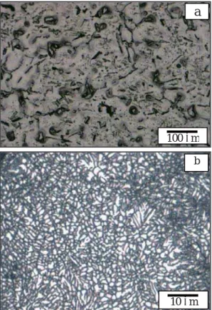
Figure 1 shows the optical microstructures of SWAP powder, as well as that of cast Mg-Al-Zn-Ca-La alloy. For cast material, flakes of precipitated compounds distributed in the matrix of g-Mg matrix are observed in Fig. 1 (a). These compounds were then analyzed using XRD analysis in which it was revealed that both Al2Ca and All1La3 compounds exist in the cast material, as shown in Fig. 2. The SWAP powder shows directional solidification in terms of dendrite structure with ultra fine size along with some amount of equi-axed grains in Fig. 1 (b). The dendrite size greatly depends on the powder
particle size through the effect of cooling rate. The secondary dendrite arm spacing (DAS) showed the value of 0.91 microns for particle sizes below 100 microns, while it showed 2.03 microns for particle sizes over 1 mm. According to the relation between DAS ( , m) and the cooling rate (R, K/s):
瑦35.5R -0.31
These values of DAS correspond to the values of cooling rates of 1.36x10⁵ and 1.02x10⁴ K/s, respectively17). No precipitation of compounds can be observed in SWAP powders, as could be also confirmed by Fig. 2 in which the XRD pattern of SWAP powders show only the peaks of g-Mg. That is due to the super-saturation of alloying elements in the matrix as a result of the use of super high cooling rates during the production of powders using SWAP process.
The DTA profiles for SWAP powder as well as for cast Mg-Al-Zn-Ca-La alloy, as shown in Fig. 3 showed an endothermic reaction due to the melting of Al2Ca phase at about 530 し. Another endothermic reaction was shown
at about 580 し due to the melting of All1La3 phase. This
means that thermal processing of both SWAP powder and cast material at temperatures below 530 し has no effect
on compound formation or melting. The last peak observed is due to melting of g-Mg.
Fig. 1 Microstructure of cast material (a) and SWAP powder (b).
a
100 m
10 m b
Transactions of JWRI, Vol.38 (2009), No. 1
Fig. 2 XRD patterns of both SWAP powder and cast billet of ZAXE1711 alloy.
Fig. 3 DTA patterns of SWAP powder and cast billet of ZAXE1711 and ZAXE1713 alloys.
As for the consolidated billets before extrusion, SPS results in the improved bonding between powder particles along with the uniform sintering and reduced internal stresses due to evenly dispersed spark plasma energy between their particles. Another very important benefit of SPS is the minimized grain growth, compared to that of conventional sintering, due to localized heating during the consolidation process. However, only the microstructure of the extruded Mg-Al-Zn-Ca-La alloy is discussed below. Figure 4 shows the observed SEM images of extruded Mg-Al-Zn-Ca-La alloy. As examples, SWAP powders containing 1.5 and 3.3% La consolidated via cold compaction and extruded at 300 and 400 し only
are shown. The grain size, which was calculated by the image analysis software, was shown to decrease as the extrusion temperature decreased. The same behavior was also observed for the case of the size of precipitated compounds. Generally, the extruded SWAP powders resulted in very fine and uniform grain sizes in the order of 0.4 to 0.5 microns, while extruded cast billets resulted in coarser grains in the order of 5 microns. Extruded SWAP powder materials indicate that both Al2Ca and Al11La3 compounds are dispersed in the structure as could
Fig. 4 Microstructures of cold-compacted and extruded ZAXE SWAP powders observed by SEM.
a- ZAXE1713, extruded at 400 し
b- ZAXE1711, extruded at 400 し
c- ZAXE1713, extruded at 300 し
be confirmed using XRD analysis. The amount and size of these precipitated compounds was shown to depend on the La content. With increasing the content of La addition, coarser precipitated compounds particles could be observed. The use of SPS process has resulted in the formation of more and coarser precipitated compounds than that of cold compacted samples. That is because of the higher temperature used for SPS process, which was 350 し.
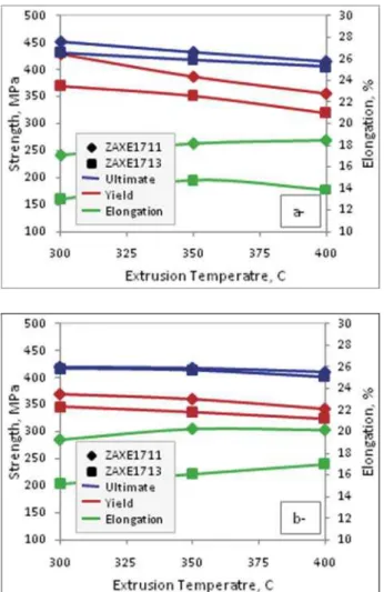
Figure 5 shows the dependence of tensile properties on the extrusion temperatures. The higher the extrusion temperature, the lower the yield, and tensile strengths of extruded Mg-Al-Zn-Ca-La alloy. That can be attributed to the strain hardening that occurs during plastic deformation of the extrusion process, which is increased in the case of extrusion at lower temperatures. It is also shown from the figure that the extruded SWAP powder could show tensile properties superior to that of cast billets, as the tensile strength for extruded cast materials had an average of 290 MPa and the yield strength had an average of 195 MPa for both alloys. This is due to the finer size of both grains and precipitated compounds of extruded SWAP powders compared to that of cast billets. The extruded SWAP powders containing 1.5% La have shown tensile properties that are much improved over that of SWAP powders containing 3.3% La. That could be attributed to the coarsening of precipitated compounds for the latter, which has overcome the grain refinement effect produced by La addition. It can also be shown from Fig. 5 that the use of rapidly solidified SWAP Mg powders alloyed with La additions could lead to improved levels of tensile strength while maintaining promising values of elongation in the range of 13 to 20%. The mechanical response of consolidated billets produced via SPS without extrusion is expected to be improved due to the effect of the better bonding between powder particles as well as minimized grain growth compared to conventional sintering. However, the effect of SPS on the mechanical response of the extruded materials in this study is minor as a result of the dominant re-crystallization effect of the hot extrusion process. This means that yield strength is exactly expressed by the Hall-Petch equation.
Fractography of the fractured tensile test specimens showed that sufficient bonding between powder particles could be obtained at the extrusion temperatures used, as no primary particle boundary was observed at the fracture surface. Generally, the fracture surface of all the fractured specimens showed dimpled pattern as an indication for ductile fracture. However, the size of dimples varied slightly among different consolidation and extrusion conditions of SWAP powders.
The tensile results of the extruded SWAP Mg-Al-Zn-Ca-La powder suggest that the strength of magnesium alloys can be effectively improved through grain refinement. Only a slight decrease within extruded SWAP powder in the grain size by extrusion at lower temperature could lead to a drastic increase in the strength. The same behavior could also be observed when
comparing extruded SWAP powder with extruded cast billet specimens.
Fig. 5 Tensile properties of extruded SWAP powders consolidated using cold compaction (a) and SPS (b).
4. Conclusions
The use of SWAP powder could lead to an effective improvement in the mechanical response of extruded Mg-Al-Zn-Ca-La alloy, compared to that of extruded cast billets. Extrusion of both SWAP powders and cast billets at lower temperatures could lead to improvement in the strength of extruded Mg-Al-Zn-Ca-La alloy. The tensile strength value of up to 450 MPa for cold compacted Mg alloy powder extruded at 300 し is very promising for the
improvement of mechanical properties of Mg alloys. Grain refinement is a very powerful tool for the improvement of the mechanical response of Mg alloys. The grain refinement mechanism is more effective for the improvement of the strength of Mg-Al-Zn-Ca-La alloys than the mechanism of the compound precipitation. A La content of 1.5% could lead to improved mechanical properties compared to that of 3.3% as a result of the good balance between its effects on grain refinement and precipitated compound formation.
Transactions of JWRI, Vol.38 (2009), No. 1
References
1) T. Murai, S. Matsuoka, S. Miyamoto, Y. Oki, Mater. Sci. Forum 419-422 (2003) 349-354.
2) Hanlin Ding, liufa Liu, Shigeharu Kamado, Wenjiang Ding, Yo Kojima, J. alloys Compd. 456 (2008) 400-406.
3) Wang Li-guo, Zhang Bao-feng, Zhu Shi-jie, Zhang Mei, Zhang Chung-xiang, Guan Shao-kang, Trans. Nonferrous Metals Soc. China, 16 (2006) 551-555. 4) Yu Yoshida, Keita Arai, Shota Itoh, Shigeharu
Kamado, Yo Kojima, Sci. Tech. Adv. Mater. 6 (2005) 185-194.
5) Z. Yang, J.P. Li, J.X. Zhang, G.W. Lorimer, J. Robson, Acta Metall. Sin. (Engl. Lett.) 21-5 (2008) 313-328. 6) Shigeharu Kamado, Junichi Koike, Katsuyoshi
Kondoh, Yoshihito Kawamura, Mater. Sci. Forum 419-422 (2003) 21-34.
7) S.J. Liang, Z.Y. Liu, E.D. Wang, Materials Letters 62 (2008) 3051-3054.
8) A. Jain, O. Duygulu, D.W. Brown, C.N. Tome, S.R. Agnew, Mater. Sci. Eng. A 486 (2008) 545-555.
9) H. Pirgazi, A. Akbarzadeh, R. Petrov, L. Kestens, Mater. Sci. Eng. A 497 (2008) 132-138.
10) T. Mukai, K. Higashi, Scripta Mater. 44 (2001) 1493-1496.
11) J.Q. Li, L. Wang, H.W. Cheng, H.F. Zhang, Z.Q. Hu, H.N. Cai, Mater. Sci. Eng. A 474 (2008) 24-29. 12) G. Garcez, M. Maeso, I. Todd, P. Perez, P. Adeva, J.
Alloys Compd 432 (2007) L10-L14.
13) P. Andersson, C.H.Caceres, J. Koike, Mater. Sci. Forum, 419-422 (2003) 123-128.
14) Yoshihito Kawamura, Akihisa Inoue, Mater. Sci. Forum, 419-422 (2003) 709-714.
15) Z.M. Zhang, C.J. Xu, X.F. Guo, Acta Metall. Sin. (Engl. Lett.) 21 (2008) 30-36.
16) Imai Hisashi, Kawakami Masashi, Kondoh Katsuyoshi, Otsuka Isamu, Izaki Hiroshi, Trans. JWRI, 36-2 (2007) 33-38.
17) S. Nishida, T. Motomura, Journal of Japan Institute of Light Metals, 58 (2008) 439-422.
Mechanical Properties and Machinability of Extruded Cu-40%Zn
Brass Alloys with Bismuth via Powder Metallurgy Process
†IMAI Hisashi*, LI shufeng*, ATSUMI Haruhiko**, KOSAKA Yoshiharu***, KOJIMA Akimichi***, UMEDA Junko*, KONDOH Katsuyoshi****
Abstract
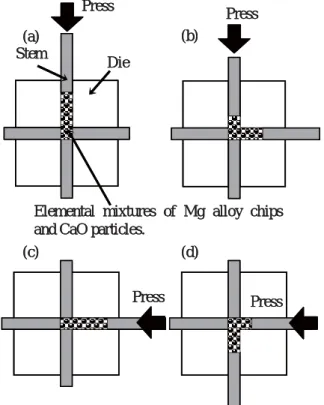
In this paper, the uniform distribution process of bismuth particles in Cu-40Zn brass alloy by powder metallurgy (P/M) and machinable lead-free P/M brass with bismuth are described. Cu-40Zn Brass with bismuth powders produced by the rapid solidification processing were used as raw materials, having mean particle sizes of 150 μm. Three kinds of billets were prepared for the extrusion, namely green compact, sintered billets by using spark plasma sintering (SPS) and cast ingot. Bismuth dispersed in brass powder formed grains and dissolved into the powder surface by the heat treatment at the temperature over the melting point of bismuth. The behavior of bismuth existing in the primary particle boundary caused a decrease in the elongation of the extruded brass. Drill cutting ability was improved for the extruded material with the continuous machining chip. The shape of the machining chip was affected by the combination of brass matrix and the distribution of bismuth.
KEY WORDS: Cu-40Zn Brass, Lead-free, Bismuth, Machinability, Machining chip
1. Introduction
Cu-Zn alloy (brass) is widely used as an industrial material because of its excellent characteristics such as high corrosion resistance, non-magnetism, and good forginability. In particular, machinable brass is obtained by adding lead 1, 2). However, it is necessary to reduce the quantity of the lead in the material from a viewpoint of the hazardous effects on the environment and humans 3, 4). The addition of bismuth (Bi), silicon (Si), selenium (Se), and graphite to brass alloys as alternative elements to lead have been discussed to improve machinability 5)-7). The quantity of Bi dissolved in copper is 0.5 wt%, similar to lead, and the adverse effect on the human body from Bi is small. However Bi disperses as several tens of microns in brass cast ingot shown in Fig.1. Therefore, the machinability of brass with Bi is inferior to that with lead8), and cracks are generated from Bi particles in the secondary phase.糫In this paper, the uniform distribution
of Bi particles in the brass alloy by powder metallurgy (P/M) was examined to develop machinable lead-free brass. Brass alloy powder supersaturated with Bi by the rapid solidification processing was produced. Fine Bi particles were dispersed uniformly in the brass matrix by the deposit of Bi during billet molding and hot extrusion process. The mechanical properties and machinability of
P/M extruded brass dispersed with Bi particles were investigated.
2. Experimental procedure
A flowchart describing the preparation of brass alloys in this study is shown in Fig.2. Brass powder, used as raw material, was prepared by the water atomization using Cu-Zn40 brass ingot with Bi additions. It had a mean particle size of 150 m. The Bi additions to brass alloy were 0, 1.0, 2.2, 2.62, 2.91, 3.23 and 5.0wt%. The thermal behavior due to microstructure changes of the as-received powder during annealing was investigated by differential thermal analysis (DTA) and thermo-gravimetric analysis (TG) (DTG-60: SHIMADZU Co.) under a heating rate of 10 K/min and 2 K/min in Ar gas atmosphere from room temperature up to 1273 K.
Spark plasma sintering (SPS: SPS SYNTEX INC., SPS-1030) and green compaction were used to consolidate the powder. In the case of SPS, the condition for consolidating the high-density sintered compact was selected using the temperature of 1053 K for 1.8ks under 40MPa pressure in vacuum 9). On the other hand, the conventional cold compaction was employed by applying a pressure of 600 MPa at room temperature by using the † Received on July 10, 2009
* Specially Appointed Researcher ** Student
*** SAN-ETSU METALS CO.,LTD
**** Professor
Transactions of JWRI is published by Joining and Welding Research Institute, Osaka University, Ibaraki, Osaka 567-0047, Japan