Study on anion conductive membranes
containing dense ammonium groups
A Doctoral Thesis
Presented to
Interdisciplinary Graduate School of Medicine and Engineering
University of Yamanashi
March 2017
Manai Shimada
Contents
Chapter 1 Introduction………..1
1.1 General Introduction………...1
1.2 Ion Conductive Polymers and its Applications………...1
1.3 Approaches to Improvement of Membrane Properties………3
1.3.1 Chemical properties………3
1.3.2 Chemical Stabilities………4
1.3.3 Mechanical properties………4
1.4 Composition of Ion Conductive Membranes………6
1.4.1 Hydrophobic Polymer Backbones………7
1.4.2 Anion Conductive Groups………….………9
1.4.3 Hydrophilic Scaffolds………10
1.4.4 After Treatment of AEMs……… 11
1.5 Fluorene containing polymers………11
1.5.1 Various applications of general fluorene compounds………11
1.5.2 Fluorene containing AEMs………….………12
1.6 Objective of This Research………...……. 13
References………...….14
Chapter 2 Anion Conductive Aromatic Polymers Containing Fluorene Groups: Effect of the Position and Number of Ammonium Groups…………21
2.2 Experimental Section………..23
2.3 Results and Discussion……….…………..……34
2.3.1 Synthesis of QPE-bl-3, QPE-bl-3 M2, QPE-bl-3 M4………34
2.3.2 Morphology of the Membranes………43
2.3.3 Water Uptake and Hydroxide Ion Conductivity………46
2.3.4 Dynamic Mechanical Properties………49
2.3.5 Gas Permeability………51
2.3.6 Fuel Cell Performance………52
2.4 Conclusion………53
References………54
Chapter 3 Anion Conductive Aromatic Polymers Containing Aliphatic and Ammonium-functionalized Fluorene Groups………56
3.1 Introduction………...……….56
3.2 Experimental Section………..57
3.3 Results and Discussion………68
3.3.1 Synthesis of QPA(C3), QPA(C6), QPA(C10).………68
3.3.2 Water Uptake and Hydroxide ion conductivity…………..………75
3.3.3 Dynamic Mechanical Properties………77
3.3.4 Mechanical Stability………78
3.3.5 Alkaline stability………...………79
References………...…….81
Chapter 4 Conclusions and Future Outlook………83
4.1 Summary of Chapters………...……….83 4.2 General Conclusion………..87 4.3 Future Outlook………..89 List of Publications………..90 Patent………91 Meeting Abstracts………93 Acknowledgement………94
1
Chapter 1
Introduction
1.1 General introduction
The technology for the global environmental issues has been rapidly progressing in the last few decades, however, still significant and continuous works are needed all over the world. More recently and internationally, variety of policies are underway suitable for regional climate and economy, as we know in Paris Agreement determining the perspective for global warming countermeasures after 2020. Japan is poor in natural resources, and it is required to lower the dependence on fossil fuels and precious metal resources. Therefore, a number of efforts have been carried out to realize low carbon society using new energy or green energy.
Another critical environmental issue is water treatment. Water shortage and water pollution have become serious by population growth, desertification, and climate change or sudden disaster. In addition to the low carbon society, it is necessary for lives to secure good quality of water as drinking water and daily water.
1.2 Ion Conductive Polymers and Their Applications
Ion conductive polymers are useful for energy applications such as batteries, electrolyzers, and fuel cells.1-3 Performance requirements of anion conductive membranes
(or ion exchange membranes: AEMs) differ from each application. As an example, electrolyzer, which is recently attractive water desalting system using proton exchange
2
membranes (PEMs) and AEMs because of the effectivity and extensibility of size, needs mild conditions for the membranes to operate at ambient temperature in neutral solution. On the other example, fuel cells which are clean energy devices converting directly and efficiently chemical energy to electricity usually operate in severer conditions. Especially among several kinds of fuel cells, anion exchange membrane fuel cells (AEMFCs) have recently attracted more attention because of their possible use of non-precious metals as electrode catalysts under alkaline conditions, while recent commercialized fuel cell vehicles rely on acidic PEMs. It is known that oxygen reduction reaction is kinetically advantageous in alkaline compared to acid. As one of the AEMFCs, liquid-fed fuel cells represented by direct hydrazine hydrate AEMFCs have been studied because hydrazine hydrate fuel is easy to handle and transport, existing infrastructure is available, high volumetric energy density than hydrogen, and the emissions are only nitrogen and water. 4-6 However, hydrazine in alkaline solution shows strong reducing power, and radical
species as by-product are severe for AEMFC components. In addition, anion conductive polymers are also used as binder in the electrode catalyst layers.7,8 Compared with AEMs,
although both ionomers should have many common chemical and physical properties, anion conductive binders should have smaller ion channels or higher gas diffusivity to conduct ions or hydrogen fuel instead of membrane forming capability in AEMs. AEMs with freedom in molecular design and synthesis would be beneficial for fuel cell applications in order to adjust the properties for each component.
3
1.3 Approaches to Improvement of Membrane Properties
One of the important challenges in AEMFCs is the development of more conductive and stable AEMs than the existing materials.9,10 Hydroxide ion conductivity is relatively
lower than proton conductivity in solid membranes partly because of lower mobility of the hydroxide ions.11,12 Hydroxide ion is strongly nucleophilic and is likely to cause
decomposition of cationic groups and the polymer main chain attached with the cationic groups.
1.3.1 Chemical properties
Several studies have been carried out to improve anion conductivity, however, highly conductive polymers have large water uptake and fuel permeation due to the hydration nature of ionic groups. To solve this issue, the following researches have been examined; 1) to obtain higher conductivity by substituting strongly basic cationic group, 2) to provide specific properties by compositing membrane, 3) to form conductive paths effectively by increasing local ionic density in the polymer,13-15 and 4) to determine the
structural design. Details of 1), 2) and 4) are described below section (1.3.2, 1.3.4, 1.4.2, respectively). Regarding 3), we have reported that hydrophobic and hydrophilic block copolymer showed well developed hydrophobic / hydrophilic phase separations and high hydroxide conductivity than the same component of random copolymer, suggesting to form conductive paths. The domain size is almost controllable, which could be
4
1.3.2 Chemical stabilities
Hydroxide ions are one of the probable species to cause degradation. In recent studies, there have been significant efforts from both experimental and computational approaches to improve chemical stability of AEMs. A DFT study suggested that the possible decomposition mechanism involves nucleophilic attack of hydroxide ions to the trialkylbenzylammonium groups or other heterocyclic amine groups (Figure 1.1, 1.2) 16-19 and the vicinal polymer backbone such as β-ether linkages, sulfone or ketone groups
(Figure 1.3)20,21, benzylimidazolium (Figure 1.4)13, and benzimidazole (Figure 1.5).22
Considering those results, variety of structures (see 1.4) were prepared and subjected to durability test of hydroxide ion conductivity.
1.3.3 Mechanical Properties
For the practical operation, AEMs were experience mechanical stress under wide ranges of humidity and temperature. It causes fatal membrane breaking via typical resin deteriorations of stress cracks and deformations. Therefore AEMs with high mechanical properties, tensile strength, tearing strength, bendability, and their small humidity and temperature dependence are needed. For example, to design polymer backbone mentioning below section (1.4.1), and to have high molecular weight are the major and
5
Figure 1.1 Potential degradation reactions of benzyltrimethylammonium under alkaline conditions: a) Hofmann elimination, b) nucleophilic substitution on methyl groups, c) nucleophilic substitution on benzylic position, d) Sommelet–Hauser rearrangement, e) Stevens rearrangement.
Figure 1.2 Potential degradation reactions of benzylhexyldimethylammonium under alkaline conditions.
Figure 1.3 Potential degradation reactions of hydrolysis of an ether bridge activated by a sulfone bridge in poly(aryleneether)sulfone under alkaline conditions.
6
Figure 1.4 LUMO energy and isosurface of the C2-substituted imidazolium cations. The order of the LUMO energy corresponds to that of the energy barriers in the ring-opening reaction. Energy is given by eV.
Figure 1.5 Reaction profiles for the two hydroxide-mediated degradation pathways (de-methylation and ring-opening) for benzimidazole. The dotted lines represent the higher energy, TS ring-opening degradation pathway.
1.4 Composition of Ion Conductive Membranes
The various chemical structure of AEMs are reported to improve chemical and mechanical properties as mentioned above. Polymer electrolyte membrane can conduct ions through ionic groups in the polymer. In general, large ion exchange capacity (IEC, the number of ionic group per gram of polymer (meq g-1)) contributes to higher ion
7
membranes. Therefore it generally consists of both hydrophobic unit as the base polymer and hydrophilic unit as ionic group or ionic group-containing substitute. In hydrophilic units, ionic groups exist as incorporated in the polymer backbone,20,25,26 a part of branched
side chain27,28 or introduced via introducing into appropriate components as a scaffold
(see 1.4.3).
1.4.1 Hydrophobic Polymer Backbones
Polymer backbones of hydrophobic units are usually based on the fine chemical polymers, proton conductive polymer backbones or their applied structures because they have already exhibited high chemical and mechanical properties. For example, chemically stable fluorocarbon polymers (e.g. perfluoroalcoxyalkane; PFA, ethylene tetrafluoroehtylene; FTFE)11,25,27,28, gas barrier and heat resistant aromatic polymers (e.g.
polyphenylene; PP, polyphenylene oxide; PPO, polysulfone; PSF),29-38 ecofriendly and
better membrane forming aliphatic polymers (e.g. polystylene, polyethylene, polyvinylalcohol)26,39, heat resistant and mechanically stable amine or imine containing
polymers (e.g. polyimide; PI, polybenzimidazol; PBI)23,24 and other arranged polymers
(e.g. poly(arylene)ether; QPE,7,8,38-43 poly(arylene)fluoroalkyl; QPAF,44,45 polyfluorene;
PFO,46 siloxane-based polymer47). However even in less OH- attacked hydrophobic units,
the properties are impaired in swelling membrane and strong alkaline circumstances. Thus the properties and decomposition mechanisms have been studied experimentally and computationally as anion conductive polymer, however the standard structure is still under being examined.
8
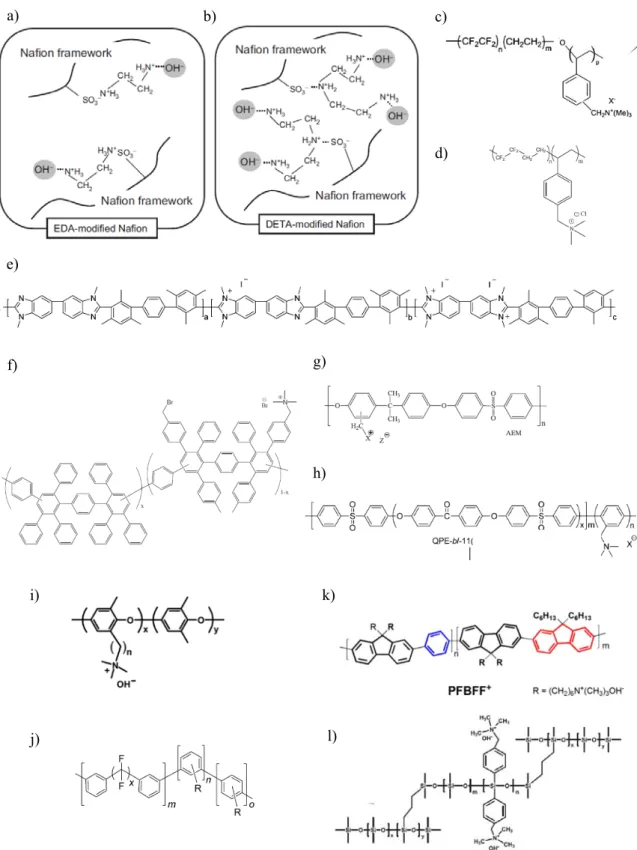
Figure 1.6 Molecular structures of AEM backbones. (a)(b) PFA-base, (c) ETFE-base, (d) Polystylene-base, (e) PBI-Polystylene-base, (f) polyphenylene-Polystylene-base, (g) PSF-Polystylene-base, (h) poly(arylene)ether-Polystylene-base, (i) PPO-Polystylene-base, (j) QPAF-base, (k) PFO-base, (l) silicate-base.
a) b) c) d) e) f) g) h) i) j) k) l)
9
1.4.2 Anion Conductive Groups
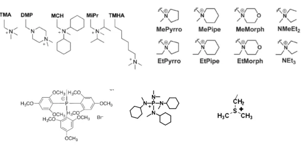
Currently, most AEMs carry quaternary ammonium groups since there are not many other options for cationic species tetherable to organic polymer chains.29,41-43 In the
literature, there are some other cations for AEMs, such as quaternary cyclic ammonium groups,31,32,44,48 phosphonium34,49,50 and tertiary sulfonium groups,39,51 (Figure 1.7)
however, the quaternary ammonium groups have been mostly investigated due to the balanced properties.52-54 Furthermore, many researchers have tried to avoid above
mentioned decomposition. For example, it was reported that proper alkyl spacers were introduced between the ammonium groups and polymer main chain, the steric structure was attached to cationic group, and imidazolium groups were directly connected to the polymer main chain. These approaches seemed to proved the alkaline stability for several hundred hours (Figure 1.8).30,44,55
10
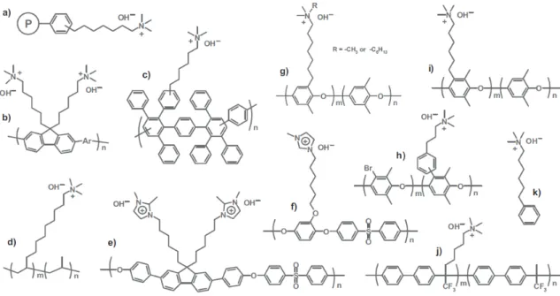
Figure 1.8 Molecular structures of AEMs with long alkyl spacer.
1.4.3 Hydrophilic scaffolds
Scaffold types of polyelectrolytes have been studied due to the applicability. The hydrophilic scaffolds are usually telechelic aromatic, namely polyaromatic or heteroaromatic compounds such as phenylene,56 biphenylene,57 fluorene,58-60 carbazole,61
chitosan62 and so on. These AEMs have the advantages that some kinds of cationic groups
or hydrophobic units are available because of several synthetic paths of functionalization27-35 or polycondensation reaction.29,37,42-46
Figure 1.9 Molecular structures of biphenylene as hydrophilic scaffold with three different anion conductive groups.
11
In addition, it is possible to characterize the structural features of the scaffolds themselves or polymer designs for AEM properties (Figure 1.9, details in 1.5).
1.4.4 After-Treatment of AEMs
The after-treatments such as cross-linking and compositing membranes have been studied as another approach to compensate and reinforce the properties. Cross-linking is carried out in crosslinkable components in the polymer backbone39,63 or cationic
groups,64-66 or to add cross-linking agent,67,68 which commonly polystyrene and
poly(arylene ether) are used as the based polymers, and quaternized ammonium group and imidazolium group as cationic groups. The purpose is normally to amend dimensional stability and mechanical strength. Composite membranes have been investigated by immersing anion conductive polymers into porous substrate or nanofiber cloth, or mixed with filler of particles or fibers.69,70 There are kinds of materials selected as composite
materials, and the composite membranes have been reported, expecting to reduce swelling and fuel permeability and to improve chemical and mechanical stability. For example, Yamaguchi et al reported that the composite AEMs of polystyrene-based quaternized polymer filled into porous substrate exhibited high conductivity, alkaline stability.70 However, the intrinsic membrane performance needs to be improved because
it essentially depends on the based polymer properties.
1.5 Fluorene containing polymers
12
Fluorene is one of aromatic compounds having fused three rings as shown in below (Figure. 1-10). The name of “fluorene” came from fluorescent feature by UV-irradiation. It has superior optical and electrical functionalities due to π conjugated structure, and has been tried to apply some organic devices, such as organic electroluminescence, organic solar cells, organic transistors, printed plastic electronics.71,72 Polydialkyl fluorene
polymers, which are expected to function for organic EL because of its high fluorescence quantum yield, have been reported several morphology; amorphous, β phase, α, α’ phase, liquid crystalline, semi-crystalline polymer, gel state network, and so on. Another example is biphenyl fluorene polymers commercialized as liquid crystalline display or camera lens because of high refractive index and low double reflection. Such properties owe to characteristic three-dimensional cardo structure which a quaternary carbon is center and around each four phenylene group orient in different direction.
1.5.2 Fluorene containing AEMs
Fluorene containing polymers have not only aromatic polymer features such as heat resistance and mechanical properties, but also steric features such as crystalline and water retention properties.73 They are expected to have wide selectivity for introducing ionic
groups and high conductivity due to the ability of high local ionic density because of the polycyclic compound. Thus, they have been investigated as functional hydrophilic scaffolds for AEMs. For instance, we have reported that QPE-bl-1 with three ammonium groups in fluorenylidene biphenylene unit achieved high hydroxide ion conductivity (144 mS cm-1 at 80 ºC),58 and QPE-bl-4 with partially fluorinated hydrophobic unit improved
13
alkaline stability (maintaining membrane form after 1 M KOH at 80 ºC).59
Some other researchers have also reported the fluorene-containing AEMs comparing with different cationic groups. Some of the polyfluorene based AEMs of similar structure have been investigated for the other applications (shown in 1.5.1) and evaluated.47
Nevertheless, the effect of fluorene-containing polymers as AEM components have not been well-studied. The effect of fluorene groups, in particular, the position and number of ionic groups on them should be investigated to customize the properties of AEMs.
Figure 1.10 Molecular structures of (a) fluorene, (b) dialkyl fluorene, (c) biphenyl fluorene.
1.6 Objective of This Research
AEMs are attractive because of the ability to apply as the electrolytes of new energy devices or deionization apparatus, however, the chemical and mechanical properties such as ion conductivity and alkaline stability are still insufficient. A lot of studies have been spent to determine and analyze chemical structures, while many of these are not clarified the causal relationship between structures and properties systematically partly because of large number of factors for the difference of synthetic, analytic methods and applications.
The purpose of this thesis is to provide the proper polymer design to improve ion conductivity and chemical and mechanical stability for fuel cells. I focused on fluorenylidene biphenylene as hydrophilic scaffold and benzyltrimethylammonium as anion conductive groups, and investigated their synthesis and structure/properties
14
relationship.
In Chapter 2, synthesis and properties of anion conductive aromatic block copolymers, QPE-bl-3, QPE-bl-3 M2, -M4, containing fluorenylidene biphenylene groups as scaffold for ammonium groups are described. These copolymers share the same main chain structure, but the position and the number of ammonium groups on a fluorenyl group differ. The main chain aimed to improve chemical stability by containing fluorinated phenylene and biphenylene groups. In addition the polymer design guidelines were studied from the moprphological point of view by change in IEC and the copolymer composition.In Chapter 3, a novel series of anion conductive copolymers, quaternized poly(phenylene alkylene)s (QPAs), containing fluorenylidene biphenylene groups as scaffold and alkylene groups in the main chain were evaluated. QPAs with alkylene spacer were expected to improve stability because of aliphatic groups with sp2 carbon chains and no heteroatom linkages, while carrying fluorene groups.
As a result, using fluorenylidene biphenylene scaffold, poly(arylene ether) based copolymers QPE-bl-3 series and alkylene-containing polyphenylene-based polymers QPA series proved some promising effects of bulky fluorenyl group for AEM properties. Even more stable structure as polymer backbone is suggested.
References
1. K.-D. Kreuer, Chem. Mater. 2014, 26, 361 2. M. A. Hickner, materialstoday 2010, 13, 5.
15
R. Kucernak, W. E. Mustain, K. Nijmeijer, K. Scott, T. Xuk and L. Zhuang, Energy
Environ. Sci., 2014, 7, 3135.
4. S. Yamazaki,K. Asazawa,H. Tanaka, and T. Ioroia, Japan Journal of The
Electrochemical Society, 2015, 162, F60
5. T. Sakamoto,H. Kishi, S. Yamaguchi, D. Matsumura, K. Tamura,A. Hori, Y. Horiuchi, A. Serov, K. Artyushkova, P. Atanassov, H. Tanakaa,e Journal of The
Electrochemical Society, 2016, 163, H951
6. E. Nishino, J. Yamada, K. Asazawa, S. Yamaguchi, M. Shimada, J. Miyake, K. Miyatake,J. Chem. Lett. 2016, 45, 664
7. N. Yokota, M. Shimada, H. Ono, R. Akiyama, E. Nishino, K. Asazawa, J. Miyake, M. Watanabe, and K. Miyatake, Macromolecules 2014, 47, 8238
8. R. Akiyama, N. Yokota, E. Nishino, K. Asazawa, and K. Miyatake, Macromolecules,
2016, 49, 4480.
9. H.-W. Zhang, D.-Z.Chen, Y. Xianze, S.-B.Yin, Fuel Cells 2015, 15, 761
10. A. Z.Weber, R. L. Borup, R. M. Darling, P. K. Das, T. J. Dursch, W. Gu, D. Harvey, A. Kusoglu, S. Litster, M. M. Mench, R. Mukundan, J. P. Owejan, k Jon G. Pharoah, M. Secanell, and I. V. Zenyuk, J. Electrochem. Soc. 2014, 161, 12, F1254
11. C. Chen, Y.-L. S. Tse, G. E. Lindberg, C. Knight, and G. A. Voth, J. Am. Chem. Soc.
2016, 138, 991.
12. I. P. Raya, M. W. Ellis, A. H.Guerrero, F. E.Blancas, J. Power Sources 2016, 307, 898. 13. Y. Zhao, K. Yoshimura, H. Shishitani, S. Yamaguchi, H. Tanaka, S. Koizumi, N.
16
14. M. Hara, T. Kimura, T. Nakamura, M. Shimada, H. Ono, S. Shimada, K. Miyatake, M. Uchida, J. Inukai, and M. Watanabe, Langmuir, 2016, 32 (37), 9557
15. J. Pan, C. Chen, Y. Li, L. Wang, L. Tan, G. Li, X. Tang, L. Xiao, J. Lu, Lin, Zhuang,
Energy Environ. Sci., 2014, 7. 354
16. C. G. Arges and V. Ramani, J. Electrochem Soc. 2013, 160 (9) F1006
17. R. Tsuchitani, H. Nakanishi, H. Shishitani, S. Yamaguchi, H. Tanaka, H. Kasai,Solid State Ionics 2015, 278, 5
18. A. G. Wright, T. Weissbach, and S. Holdcroft, Angew. Chem. Int. Ed. 2016, 55, 4818 19. S. A. Nunez, C. Capparelli, and M. A. Hickner, Chem. Mater., 2016, 28 (8), 2589 20. Y. K. Choe, C. Fujimoto, K. S. Lee, L. T. Dalton, K. Ayers, N. J. Henson, Y. S. Kim,
Chem. Mater. 2014, 26, 5675.
21. C. G. Arges, V. Ramani, Proc. Natl. Acad. Sci. U. S. A. 2013, 110, 2490.
22. B. R. Caire, Melissa A. Vandiver, T. P. Pandey, A. M. Herring, and M. W. Liberatore,
J. Electrochem. Soc. 2016, 163 (10) H964
23. R. Narducci, J.-F. Chailan, A. Fahs, L. Pasquini, M. L. D. Vona, P. Knauth, J. Polym.
Sci. B: 2016, 54, 1180
24. A. G. Wright, J. Fan, B. Britton, T. Weissbach, H.-F. Lee, E. A. Kitching, T. J. Peckham and S. Holdcroft, Energy Environ. Sci. 2016, 9, 2130
25. H. Cho,1,2 Dirk Henkensmeier,1,3 Mateusz Brela,4 Artur Michalak,4 Jong Hyun Jang, Kwan-Young Lee, J. Polym. Sci. B: 2016, 10.1002/polb.24267
26. W. Germer, J. Leppin, C. N. Kirchner, H. Cho, H.-J. Kim, D. Henkensmeier, K.-Y. Lee, M. Brela, A. Michalak, A. Dyck, Macromol. Mater. Eng. 2015, 300, 497
17
27. K. Miyazaki, N. Sugimura, K. Kawakita, T. Abe, K. Nishio, H. Nakanishi, M. Matsuoka, and Z. Ogumia, J. The Electrochem. Soc. 2010, 157, 11, A1153
28. M. Zhang, C. Shan, L. Liu, J. Liao, Q. Chen, M. Zhu, Y. Wang,L. An, and N. Li, ACS
Appl. Mater. Interfaces 2016, 8, 23321
29. S. D. Poynton , J. R. Varcoe, Solid State Ionics 2015, 277, 38
30. K. Yoshimura, H. Koshikawa, T. Yamaki, H. Shishitani, K. Yamamoto, S. Yamaguchi, H. Tanaka, Y. Maekawa, J. Electrochem. Soc. 2014, 161 (9) F889
31. L. Wu, Y. Zhao, L. Ge, Z. Yang, C. Jiang, T. Xu, Chem. Engineering Sci. 2015, 135, 526
32. H.-S. Dang, P. Jannasch, Macromolecules 2015, 48, 5742−5751
33. T. Jurzinsky*, C. Cremers, F. Jung, K. Pinkwart, J. Tu¨bke, Int. J. Hyd. Ener. 2015,
40, 11569
34. X. Lin, L. Wu, Y. Liu, A. L. Ong, S. D. Poynton, J. R. Varcoe, T. Xu,J. Power Sources, 2012, 217, 373
35. Z. Wang,∗ J. Parrondo,∗∗ and V. Ramani, J, Electrochem, Soc. 2016, 163 (8) F824 36. M. I. Khan, A. N. Mondal, B. Tong, C. Jiang, K. Emmanuel, Z. Yang, L. Wu, T. Xu,
Desalination 2015 xxx–xxx
37. Y. Liu a, B. Zhang b, C. L.Kinsinger a, Y. Yang c, S. Seifert d, Y. Yan. M. Maupin a, M. W. Liberatore e, A. M. Herring, J. Memre. Sci. 2016, 506, 50
38. M. Iravaninia1, S. Rowshanzamir, FUEL CELLS 2016, 16, No. 1, 135–149
39. M. A. Hossain 1, H. Jang 1, S. C. Sutradhar, J. Ha, J. Yoo, C. Lee, S. Lee, W. Kim,
18
40. N. Li, M. D. Guiver, Macromolecules 2014, 47, 2175
41. Y. Li, Y. Liu, A. M. Savage, F. L. Beyer, S. Seifert, A. M. Herring, and D. M. Knauss,
Macromolecules 2015, 48, 6523
42. Y. Gao, F. Song, J. Qiao, S. Chen, X. Zhao, J. Zhang, Electrochim. Acta 2015, 177, 201
43. C. G. Arges, L. Wang, M. Jung, V. Ramani, J. Electrochem. Soc. 2015, 162, F686 44. H. Ono, J. Miyake, S. Shimada, M. Uchidabd, K. Miyatake, J. Mater. Chem. A, 2015,
3, 21779–21788
45. H. Ono, J. Miyake, K. Miyatake, J. Polym. Sci., Part A: Polym. Chem. 2017, DOI:10.1002/pola.28513
46. L.-J. Ghil a, J. Kim, J. Membr. Sci. 2016, 508,1
47. W.-H. Lee, A. D. Mohanty, and C. Bae, ACS Macro Lett. 2015, 4, 453−457 48. K. M. Hugar, H. A. Kostalik, G. W. Coates, J. Am. Chem. Soc., 2015, 137, 8730 49. T. Ikeda,* S. Moriyama, J. Kim, Macromol. Chem. Phys. 2016, 217, 2551
50. C. T. Womble,† G. W. Coates,‡ K. Matyjaszewski,† and K. J. T. Noonan, ACS Macro
Lett. 2016, 5, 253−257
51. M. A. Hossain, H. Jang, S. C. Sutradhar, J. Ha, J. Yoo, C. Lee, S. Lee, W. Kim, Int.
Hyd. Ener. 2016, 10458
52. J. Miyake, K. Fukasawa, M. Watanabe, K. Miyatake, J. Polym. Sci. Part A: Polym.
Chem. 2014 52, 383–389.
53. M. R. Hibbs, J. Polym. Sci. Part B: Polym. Phys. 2013, 51, 1736–1742. 54. M. Mamlouk, K. Scott, J. Power Sources 2012, 211, 140-146.
19
55. P. Jannasch , * E. A. Weiber, Macromol. Chem. Phys. 2016, 217, 1108 56. E. A. Weiber, P. Jannasch, J. Membr. Sci. 2016, 520, 425
57. Z. Hu1, W. Tang1, D.Ning1, X. Zhang1, H. Bi1, S. Chen, FUEL CELLS 2016, 16, No. 5, 557–567
58. M. Tanaka, K. Fukasawa, E. Nishino, S. Yamaguchi, K. Yamada, H. Tanaka, B. Bae, K. Miyatake, and M. Watanabe, J. Am. Chem. Soc. 2011, 133, 10646–10654
59. H. Ono, J. Miyake, B. Bae, M. Watanabe, K. Miyatake, Bull. Chem. Soc. Jpn. 2013,
86, 663-670.
60. A. N. Lai, K. Zhou, Y. Z. Zhuo, Q. G. Zhang n, A. M. Zhu, M. L. Ye, Q. L. Liu, J.
Membr. Sci. 2016, 497, 99
61. J.-L. Wang, L.-L. Wang, R. Feng, Y. Zhang, Solid State Ionics 2015, 278, 144
62. T. P. Pandey, H. N. Sarode, Y. Yang, Y. Yang, K. Vezz` u, V. D. Noto, S. Seifert, D. M. Knauss, M. W. Liberatore, and A. M. Herring, J. Electrochem. Soc. 2016, 163 (7) H513
63. Y. Z. Zhuo, A. N. Lai, Q. G. Zhang n, A. M. Zhu, M. L. Ye, Q. L. Liu, J. Membr. Sci.
2015, 491, 138
64. A. Amel, S. B. Smedley, D. R. Dekel, M. A. Hickner, and Y. E.-Elia, J. Electrochem.
Soc. 2015, 162 (9) F1047
65. Q. Pan, M. M. Hossain, Z. Yang, Y.Wang, L. Wu, T. Xu, J Membr. Sci., 2016, 515, 115
66. J. Pan, L. Zhu, J. Han, and M. A. Hickner, Chem. Mater. 2015, 27, 6689
20
68. T. Watanabe, M. Tanaka and H.i Kawakami, Nanoscale, 2016, 8, 19614
69. L.-L. Wang, J.-L. Wang , Y. Zhang, R. Feng, J. Electroanal. Chem. 2015, 759, 174 70. G. S. Sailaja, P. Zhang, G. M. Anilkumar, T. Yamaguchi, ACS Appl. Mater. Interfaces
2015, 7, 6397
71. Xie, L.-H.; Yin, C.-R.; Lai, W.-Y.; Fan, Q.-L.; Huang, W. Prog.Polym. Sci. 2012,
37, 1192−1264.
72. J-Y Lin, W.-S. Zhu, F. Liu,‡ L.-H. Xie, L. Zhang, R. Xia, G.-C. Xing, W. Huang,
Macromolecules 2014, 47, 1001
21
Chapter 2
Anion Conductive Aromatic Polymers Containing Fluorene Groups:
Effect of the Position and Number of Ammonium Groups
2.1 Introduction
In a recent study, there have been significant efforts from both experimental and computational approaches to improve anion conductivity and chemical stability of ammonium-functionalized polymers. For instance, polymers with dense ammonium groups are claimed to show higher hydroxide ion conductivity than 0.1 S/cm at high temperature in water,1-3 which is comparable to that of inorganic base aqueous
solution. It was reported that the steric and conjugated onium groups were chemically stable in alkaline media for several hundred hours.4-9 A DFT study
suggested that the possible decomposition mechanism involved nucleophilic attack of hydroxide ions to the trialkylbenzylammonium groups10-12 and the vicinal polymer
backbone such as β-ether linkages.13 Therefore, proper alkyl spacers were introduced
between the ammonium groups and polymer main chain provided to improve the alkaline stability.
In my laboratory, aromatic block copolymers composed of rigid and linear hydrophobic unit and ammonium-functionalized hydrophilic unit have been studied aiming to form ion conductive pathway based on hydrophilic/hydrophobic phase separation. In the hydrophilic component, fluorenyl biphenylene groups were adopted as scaffold for ammonium groups to realize high dense ammonium groups or high local ion exchange capacity (IEC). The maximum hydroxide ion conductivity of the block copolymer membrane was as high as 144 mS/cm in water at 80 °C, which
22
was much higher than that of the random copolymer membrane of the same chemical component. A noble metal free fuel cell was operated with the membrane to achieve the maximum power density of 161 mW/cm2 at a current density of 446 mA/cm2
using aqueous hydrazine/KOH solution as the fuel.14,15 The polymer membrane,
however, was not very stable in hydrazine/KOH media. Partial fluorination was effective in improving the alkaline stability of the polymer main chains.14,16 In these
studies, the position and number of ammonium groups in the hydrophilic unit were limited and their effect on the membrane properties was not investigated.
In this chapter, to evaluate the effect of ammonium-functionalized fluorenlydene biphenylene groups on the membrane properties in more details, three series of aromatic block copolymers were designed and synthesized, in which the number and position of ammonium groups were well-controlled. The polymers were synthesized via either post-chloromethylation or polymerization of pre-aminated monomers. The chemical structure, phase-separated morphology, water uptake, hydroxide ion conductivity, and mechanical properties were compared among the polymer membranes. The best performing membrane was then tested in fuel cell operation.
23
2.2 Experimental Section
Materials
9,9-Bis(hydroxyphenyl)fluorene (BHF) (> 97%, TCI), dimethylamine (> 40wt%, Kanto Chemical), formic acid (35-37wt%, Kanto Chemical), tetrahydrofuran (Kanto Chemical), ethanol (97%, Kanto Chemical), decafluorobiphenyl (DFBP) (> 98%, TCI), hexafluorobisphenol A (HFBPA) (> 98%, TCI), toluene dehydrated (> 99.5%, Kanto Chemical), chloromethyl methyl ether (CMME) (> 94%, Kanto Chemical), 0.5 M zinc chloride in tetrahydrofuran solution (Aldrich), 1,1,2,2-tetrachloroethane (TCE) (> 98%, Kanto Chemical), 45wt% trimethylamine aqueous solution (Aldrich), and iodomethane (Kanto Chemical) were used as received. N,N-Dimethylacetamide (DMAc) (> 99%, Kanto Chemical) was dried over molecular sieves 4 Å at least 1 day before use. Potassium carbonate (Kanto Chemical) was dried in a vacuum oven at least 12 h before use. Other chemicals were of commercially available grade and used as received.
Synthesis of Hydrophobic Oligomer 1
A typical procedure for the hydrophobic oligomer 1 is as follows. A three-necked flask with a nitrogen inlet and a Dean-Stark trap was charged with HFBPA (1.09 g, 3.24 mmol), K2CO3 (1.12 g, 8.11 mmol), DMAc (7.5 mL), and toluene (3 mL). The
mixture was heated at 160 °C for 3 h for azeotropic dehydration in nitrogen atmosphere. The mixture was cooled down to room temperature. DFBP (1.00 g, 2.99 mmol) in DMAc (2.5 mL) solution was added to the mixture. The reaction was carried out at 50 °C for 3 h. After the reaction, the mixture was poured into a large excess of deionized water. The resulting precipitate was collected by filtration. The
24
crude product was washed with hot water and hot methanol several times, and dried at 60 °C in a vacuum oven to obtain oligomer 1 in 93% yield. In a similar manner, hydrophobic oligomers with different chain lengths and end groups were synthesized by changing the feed ratio of the comonomers.
Synthesis of Hydrophilic Precursor Oligomer 2
A typical procedure for the hydrophilic precursor oligomer 2 for QPE-bl-3 is as follows. A three-necked flask with a nitrogen inlet and a Dean-Stark trap was charged with BHF (1.18 g, 3.36 mmol), K2CO3 (1.04 g, 7.50 mmol), DMAc (7.5 mL), and
toluene (3 mL). The mixture was heated at 160 °C for 3 h for azeotropic dehydration in nitrogen atmosphere. The mixture was cooled down to room temperature. DFBP (1.00 g, 2.99 mmol) in DMAc (2.5 mL) solution was added to the mixture. The reaction was carried out at 60 °C for 3 h. Then, additional BHF (0.12 g, 0.34 mmol) was added to ensure the end-capping reaction. After the reaction for another 1 h, the mixture was poured into a large excess of deionized water. The resulting precipitate was collected by filtration. The crude product was washed with hot water and hot methanol several times, and dried at 60 °C in a vacuum oven to obtain oligomer 2 in 89% yield. In a similar manner, hydrophilic precursor oligomers with different chain lengths were synthesized by changing the feed ratio of the comonomers.
Synthesis of Block Copolymers of PE-bl-3
A typical procedure for the block copolymerization is as follows (PE-bl-3). A three-necked flask with a nitrogen inlet was charged with hydrophobic oligomer 1 (0.74 g, 0.22 mmol), hydrophilic precursor oligomer 2 (1.85 g, 0.22 mmol), K2CO3
(0.046 g, 0.33 mmol), and DMAc (15 mL). The polymerization reaction was carried out at 60 °C for 6 h. After the reaction, the mixture was poured into a large excess
25
of deionized water. The resulting precipitate was washed with hot water and hot methanol several times, and dried at 60 °C in a vacuum oven to obtain PE-bl-3 in 87% yield. In a similar manner, PE-bl-3 M2 and M4 were synthesized from 3 and 4, respectively.
Synthesis of CMPE-bl-3
A typical procedure for the chloromethylation reaction of PE-bl-3 is as follows. A flask was charged with PE-bl-3 (1.00 g, 0.22 mmol) and TCE (26.7 mL). In a glove box charged with nitrogen, excess of CMME (7.0 mL, 97.7 mmol) and ZnCl2 (2.4
mL, 1.22 mmol) were added to the mixture. The reaction was carried out at 50 °C for 48 h in the sealed flask. After the reaction, the mixture was poured into a large excess of MeOH. The resulting precipitate was washed with hot methanol several times, and dried at 40 °C in a vacuum oven to obtain CMPE-bl-3 in 98% yield.
Membrane Preparation and Quaternization of CMPE-bl-3
CMPE-bl-3 (1.00 g) was dissolved in TCE (10 mL) and filtered. The filtrate was cast on a flat glass plate and heated at 60 °C for 4 h to dryness to obtain a CMPE-bl-3 membrane (ca. 50 μm thick). The resulting membrane was immersed in a large excess of 45 wt% TMA aqueous solution at room temperature for 48 h. The membrane was washed with and stored in degassed water.
26
27
Synthesis of 9,9-Bis(3-dimethylaminomethyl-4-hydroxyphenyl)fluorene (BHF-M2)
A one-necked flask was charged with BHF (4.00 g, 11.4 mmol), ethanol (24 mL), formaldehyde (6.0 mL, 79.9 mmol), and dimethylamine (7.2 mL, 57.07 mmol). The mixture was stirred at 40 °C for 24 h. The resulting precipitate was collected by filtration. The crude product was washed with hot methanol and water several times, and dried at 40 °C in a vacuum oven to obtain BHF-M2 in 83% yield. 1H NMR (500
MHz, TCE-d2, δ in ppm): 6.65-6.67 (2H, d, Ha), 7.00-7.02 (4H, d, Hb), 7.26-7.29
(2H, t, Hd), 7.34-7.38 (4H, m, Hc,e), 7.74-7.76 (2H, d, Hf), 3.72 (4H, s, Hi), 2.25
(12H, s, Hj).
Synthesis of 9,9-Bis(3,5-bis(dimethylaminomethyl)4-hydroxyphenyl)fluorene (BHF-M4)
A one-necked flask was charged with BHF (4.00 g, 11.4 mmol), tetrahydrofuran (24 mL), formaldehyde (6.0 mL, 79.9 mmol), and dimethylamine (7.2 mL, 57.07 mmol). The mixture was stirred at 50 °C for 24 h. The resulting precipitate was collected by filtration. The crude product was washed with hot methanol and water several times, and dried at 40 °C in a vacuum oven to obtain BHF-M4 in 91% yield.
1H NMR (500 MHz, TCE-d2, δ in ppm): 6.75-6.77 (2H, s, Hb), 7.21-7.38 (3H, m, Hc,
d, e), 7.74-7.76 (1H, d, Hf) , 3.71 (8 H, s, Hi), 2.24 (24 H, s, Hj).
Scheme 2-2 Synthesis of (a) BHF-M2 and (b) BHF-M4. (a)
28
29
Synthesis of Hydrophilic Precursor Oligomer 3
A typical procedure for the hydrophilic precursor oligomer 3 for QPE-bl-3 M2 is as follows. A three-necked flask with a nitrogen inlet was charged with BHF M2 (1.42 g, 4.27 mmol), DFBP (1.58 g, 3.42 mmol), K2CO3 (1.18 g, 8.54 mmol), and
DMAc (15 mL). The reaction was carried out at 60 °C for 6 h. Then, additional DFBP (0.16 g, 0.34 mmol) was added to ensure the end-capping reaction. After the reaction for another 1 h, the mixture was poured into a large excess of deionized water. The resulting precipitate was collected by filtration. The crude product was washed with hot water and hot methanol several times, and dried at 60 °C in a vacuum oven to obtain oligomer 3 in 84% yield. In a similar manner, hydrophilic precursor oligomers
3 with different chain length were synthesized by changing the feed ratio of the
comonomers.
Synthesis of Hydrophilic Precursor Oligomer 4
A typical procedure for the hydrophilic precursor oligomer 4 for QPE-bl-3 M4 is as follows. A three-necked flask with a nitrogen inlet was charged with BHF M4 (1.00 g, 2.99 mmol), DFBP (1.09 g, 3.24 mmol), K2CO3 (1.12 g, 8.11 mmol), and
DMAc (20 mL). The reaction was carried out at 60 °C for 6 h. Then, additional DFBP (0.11 g, 0.32 mmol) was added to ensure the end-capping reaction. After the reaction, the mixture was poured into a large excess of deionized water. The resulting precipitate was collected by filtration. The crude product was washed with hot water and hot methanol several times, and dried at 60 °C in a vacuum oven to obtain oligomer 4 in 87% yield. In a similar manner, hydrophilic precursor oligomers 4 with different chain length were synthesized by changing the feed ratio of the
30
comonomers.
Synthesis of Block Copolymers of PE-bl-3 M2 and M4.
A typical procedure for the block copolymerization is as follows (PE-bl-3 M2). A three-necked flask with a nitrogen inlet was charged with hydrophobic oligomer 1 (0.14 g, 0.02 mmol), hydrophilic precursor oligomer 3 (0.36 g, 0.02 mmol), K2CO3
(0.006 g, 0.04 mmol), and DMAc (5 mL). The polymerization reaction was carried out at 60 °C for 8 h. After the reaction, the mixture was poured into a large excess of deionized water. The resulting precipitate was washed with hot water and hot methanol several times, and dried at 60 °C in a vacuum oven to obtain PE-bl-3 M2 in 89% yield. In a similar manner, PE-bl-3 M4 were synthesized from 1 and 4, respectively.
Quaternization and Membrane Preparation of QPE-bl-3 M2 and M4.
A typical procedure for the quarternization reaction of QPE-bl-3 M2 is as follows. A one-necked flask was charged with PE-bl-3 M2 (1.00 g, 0.59 mmol of dimethylbenzylamine groups), CH3I (0.20 g, 1.42 mmol) and DMAc (10 mL). The
reaction was carried out at 40 °C for 24 h in a sealed flask. After the reaction, the mixture was cast on a flat glass plate and heated at 60 °C for 4 h to obtain a Q3 M2 membrane (ca. 50 μm thick). In a similar manner, PE-Q3 M2s and PE-bl-3 M4s with different copolymer compositions were quaternized.
Exchange of Counter Ions of the Quarternized Membranes
31
room temperature for 48 h. The membranes were washed with and stored in degassed water.
Measurements
1H and 19F NMR spectra were obtained on a JEOL JNM-ECA/ECX500 using
CDCl3 for BHF-M4, 1, 2, 3, and PE-bl-3s, and deuterated 1,1,2,2-tetrachloroethane
(TCE-d2) for BHF-M2, CMPE-bl-3s, PE-bl-3 M2s, and PE-bl-3 M4s, and DMSO-d6
for QPE-bl-3s, QPE-bl-3 M2s, and QPE-bl-3 M4s as solvents and tetramethylsilane (TMS) as an internal reference. Molecular weight was measured with a gel permeation chlomatography (GPC) equipped with a Jasco 805 UV detector, a Shodex SB-803 HQ column for oligomers and a Shodex K-805L for polymers using DMF containing 0.01 M LiBr as eluent. Molecular weights were calibrated with standard polystyrene samples. For transmission electron microscopic (TEM) observation, membrane samples were stained with tetrachloroplatinate ions by ion exchange of the ammonium groups in a 0.5 M K2[PtCl4] aqueous solution, rinsed with deionized
water, and dried in a vacuum oven at 40 °C for 8 h. The stained membranes were embedded in epoxy resin, sectioned to 50 nm thickness with a Leica microtome Ultracut UCT, and placed on copper grids. Images were taken on a Hitachi H-9500 transmission electron microscope with an acceleration voltage of 200 kV.
The hydroxide ion conductivities of the membranes were measured in degassed, deionized water (18 MΩ cm) at 30, 40, 60, and 80 °C using a four-probe conductivity cell attached with AC impedance spectroscopy (Solartoron 1255B, Solartron Inc.) Ion conducting resistances (R (Ω)) were determined from the impedance plots obtained in the frequency range from 1 to 105 Hz. The hydroxide ion conductivity
32
(σ (S/cm)) was calculated from the equation σ = (l / A × R), where l (cm) is the distance between inner two probes and A (cm2) is the conducting area. Water uptake
(ΔW (%)) measurement was carried out in degassed, deionized water at room temperature for 24 h. Drying the membranes in a vaccum oven at 60 °C for 8 h provided a dry weight (Wd (g)). Wet weight (Ww (g)) was measured after wiping off the surface water carefully with tissue paper. The water uptake of the membranes was calculated from the equation, ΔW(%) = (Ww - Wd) / Wd × 100.
Dynamic mechanical analysis (DMA) was carried out with an ITK DVA-225 dynamic viscoelastic analyzer. Relative humidity (RH) dependence of storage modulus (E' (Pa)), loss modules (E'' (Pa)), and tan δ at 80 °C was obtained for the membranes (5 mm × 30 mm) at a humidification rate of 1 %RH min-1 from 0% to
90%.
Gas permeability was measured with a GTR-XFYC gas permeation measurement apparatus equipped with a Yanaco G2700T gas chloromatography and a Porapak-Q column and a TCD detector. Argon and helium were used as carrier gases for the measurement of hydrogen and oxygen, respectively. Gas permeation coefficient, Q (cm3 (STD) cm/cm2 s cmHg) was calculated by the following equations, Q = 273/T
× 1/A × B × 1/t × l × 1/(76-PH2O) where T (K) is the absolute temperature of the cell,
A (cm2) is the permeation area, B (cm3) is the amount of permeated test gas, t (s) is
the sampling time, l (cm) is the thickness of the membrane and PH2O (cmHg) is the
water vapor pressure. The measurement was carried out at 80 °C and 30, 60, and 90% RH.
33
Preparation of Catalyst Coated Membrane (CCM)
A zirconia pot was charged with platinum catalysts supported on carbon black (TEC10E50E, Tanaka Kikinzoku Kogyo Co., ltd.), water, and 1-propanol. The mixture was stirred with a ball mill at 270 rpm for 30 min. Commercially available anion conductive ionomer Tokuyama AS-4 (AS-4 / carbon black = 0.8 by weight) was added to the mixture, which was stirred for another 30 min to obtain the catalyst ink. The obtained ink was sprayed on both sides of the QPE-bl-3 membrane (x5y10, IEC = 1.7 meq/g, 62 μm thick in hydroxide ion form) by pulse-swirl-spray technique. The loading amount of Pt was 0.22 g/cm2 for the anode and 0.20 g/cm2 for the
cathode, respectively. The obtained catalyst-coated membrane (CCM) was pressed at 10 kf/cm2 at room temperature for 3 min.
Fuel Cell Operation
The CCM was sandwiched by two gas diffusion layers (25BC, SGL Carbon Group Co., ltd.) and mounted into a single cell in which the electrode area was 4.41 cm2. The flow fields were serpentine and comb-shaped for the anode and the cathode,
respectively. The fuel cell was pre-operated at 40 °C and 30 mA/cm2 for 3 h. The
fuel cell was operated with fully humidified (100% RH) hydrogen and oxygen at 40 °C. The flow rate was set at 100 mL/min for both gases.
34
2.3 Results and Discussion
2.3.1 Synthesis of QPE-bl-3, QPE-bl-3 M2, QPE-bl-3 M4.
Three kinds of ammonium-functionalized copolymers with different positions and number of ammonium groups, QPE-bl-3, QPE-bl-3 M2, and QPE-bl-3 M4, were synthesized as shown in Scheme 1. The quantitative and regioselective introduction of ammonium groups in the polymers was achieved by 1) optimizing the reaction conditions of the chloromethylation reaction for the block copolymers (QPE-bl-3) or 2) by using pre-aminated monomers (QPE-bl-3 M2 and M4). QPE-bl-3s with two ammonium groups on the fluorenyl groups were prepared via the method 1. Oligomers and block copolymers were prepared by typical aromatic nucleophilic substitution reaction under basic conditions. Details on the synthesis and characterization of telechelic hydrophobic oligomers 1 were reported in our previous report (Figure 2-1 and 2-2).27 The hydrophilic precursor oligomers 2 were prepared
from BHF and DFBP under the conditions similar to those for 1. The oligomers 2 were obtained as a white powder, and characterized by 1H NMR and 19F NMR spectra,
in which the peaks were well assigned to the main chain structure and the terminal BHF groups (Figure 2-3). The chain lengths or numbers of repeat units (y) estimated from the integral ratios of peaks were in fair agreement with those calculated from the feed comonomer ratios and GPC data (Table 2-1).
35
Figure 2-1. (a) 1H NMR spectrum and (b) 19F NMR spectrum of oligomer 1 for PE-bl-3.
Figure 2-2. (a) 1H NMR spectrum and (b) 19F NMR spectrum of oligomer 1 for PE-bl-3 M2 and M4.
Figure 2-3. (a) 1H NMR spectrum and (b) 19F NMR spectrum of oligomer 2
(a) (b)
(a) (b)
36
Table 2-1 Characterization of QPE-bl-3, QPE-bl-3 M2 and M4
aCalculated from the feed comonomer ratios. bDetermined by GPC (calibrated with polystyrene standards). cDetermined by 1H NMR spectra. dMeasured for PE-bl-3, PE-bl-3 M2 and M4. eDegree of ionization = (number of ammonium group / fluorenyl biphenylene unit) calculated from 1H NMR spectra.
Poly mers xa xb xc ya yb yc nb Mnb ,d Mwb ,d DIe IECc (meq/g) Ea (kJ/mol) QPE- bl-3 4 5.1 5.3 16 15.9 16.2 8.9 117 469 1.7 2.1 19.8 5 8.9 4.5 10 13.9 11.2 4.1 54 153 1.8 1.7 15.9 8 9 8.3 6 6.3 5.8 15.9 167 1013 1.9 1.0 12.3 16 17.2 12.5 4 5.5 5.1 5.0 66 162 1.9 0.8 24.2 QPE- bl-3 M2 10 7 10 16 25 20 4.3 108 1074 2.0 1.6 14.1 6 4 5 8 10 8 3.4 38 124 2.0 1.1 18.3 16 12 16 6 6 6 3.5 56 203 2.0 0.7 15.0 QPE- bl-3 M4 6 4 5 4 6 4 2.7 40 606 4.0 1.6 11.1 12 9 12 8 10 6 8.7 107 1013 4.0 1.3 12.3 16 12 16 4 4 4 5.5 69 190 4.0 1.0 12.8
37
The precursor block copolymers PE-bl-3s were synthesized from 1 and 2. PE-bl-3s were characterized by 1H NMR and 19F NMR spectra, which suggested multiblock
copolymer structure containing equimolar amount of 1 and 2 (Figure 2-4). The molecular weights estimated from the GPC data were greater than 66 kDa for Mn and 162 kDa for Mw suitable for membrane formation. The molecular weight distribution (Mw/Mn) was relatively high (2.5-6.1) probably because of a small amount of cross-linking and/or branching reactions at the perfluorobiphenylene groups.
The chloromethylation reaction of PE-bl-3s was carried out with chloromethyl methyl ether via Friedel-Crafts reaction with ZnCl2 as Lewis acid catalyst (Scheme 2).
The chemical structure of the resulting chloromethylated copolymers was analyzed by the 1H NMR and 19F NMR spectra (Figure 2-5). It was suggested that the chloromethyl
groups were selectively substituted at 2 and 7 positions on fluorenyl groups while the other aromatic protons including hydrophobic component derived from the oligomer 1 were intact under the reaction conditions. Perfluorobiphenylene groups were also unlikely to be involved in the chloromethylation reaction as suggested by the 19F NMR spectra
(Figure 2-5(b)). The degree of chloromethylation per fluorenyl group was estimated from the integral ratios in the 1H NMR spectra to be 1.7 - 1.9. The results were similar to those
of our previous block copolymers containing fluorenyl groups.27 The obtained
CMPE-bl-3s provided self-standing, pale yellow, transparent, and thin membranes by casting from the solution. The CMPE-bl-3 membranes were quaternized by Menshutkin reaction in TMA aqueous solution. The membranes became bright yellow and insoluble in less polar solvents such as CHCl3 and TCE after the quaternization. Complete conversion of the
38
chloromethyl groups to benzyltrimethylammonium groups was suggested by 1H NMR
spectra (Figure 2-6), in which methylene protons shifted to lower magnetic field and ammoniomethyl groups were observed.
Figure 2-4. (a) 1H NMR and (b) 19F NMR spectrum of PE-bl-3.
Figure 2-5. (a) 1H NMR and (b) 19F NMR spectrum of CMPE-bl-3.
Figure 2-6. (a) 1H NMR and (b) 19F NMR spectrum of QPE-bl-3.
(a) (b)
(a) (b)
39
QPE-bl-3 M2 and M4 containing two and four ammonium groups per fluorenyl group, respectively, were prepared from the corresponding pre-aminated monomers via the method 2. The pre-aminated monomers, BHF-M2 and BHF-M4, were synthesized by Mannich reaction under the slightly modified conditions from those in the literature. Both BHF-M2 and BHF-M4 were well-characterized by 1H NMR spectra, in which
regioselective and quantitative substitution of dimethylaminomethyl groups was confirmed (Figure 2-7). Oligomers 3 and 4 were prepared from DFBP with BHF-M2 and BHF-M4. The aminated oligomers were designed to contain DFBP terminals for better reactivity than the the aminated BHF terminals in the following block copolymerization. The oligomers were soluble in organic solvents such as TCE and DMSO, and in diluted HCl aqueous solution. The 1H NMR and 19F NMR spectra suggested the formation of 3
and 4 with expected main chain and terminal structures (Figure 2-8 and 2-9). Dimethylaminomethyl groups were intact during the oligomerization reaction. Similar to the oligomers 2, y values in 3 and 4 were estimated from the integral ratios of the peaks, which were in fair agreement with those calculated from the feed comonomer ratios and the GPC data (Table 1). Block copolymers were then synthesized from 1 with 3 or 4. The block copolymerization reactions were successful to provide high molecular weight PE-bl-3 M2s and M4s under the conditions similar to those for PE-PE-bl-3s. The 1H NMR spectra
suggested the formation of multiblock copolymers containing equimolar amount of each component (Figure 2-10 and 2-11). PE-bl-3 M2s and PE-bl-3 M4s were quaternized with methyl iodide in DMAc solution (Scheme 3). The recovered quaternized polymers, QPE-bl-3 M2s and M4s, were analyzed by 1H NMR spectra (Figures 2-12 and 2-13), in which
40
complete quaternization was suggested by the shift of methylene and methyl protons attached to nitrogen atoms to the lower magnetic field.
The membranes cast from the solutions were yellow and transparent, and more ductile than QPE-bl-3 membranes with comparable IEC values. The chain lengths, molecular weights, and IECs of the membranes are summarized in Table 2-1.
Figure 2-7. 1H NMR spectrum of (a) BHF-M2 and (b) BHF-M4. (a)
41
Figure 2-8. (a) 1H NMR and (b) 19F NMR spectrum of oligomer 3.
Figure 2-9 (a) 1H NMR and (b) 19F NMR spectrum of oligomer 4.
Figure 2-10. (a) 1H NMR and (b) 19F NMR spectrum of PE-bl-3 M2.
(a) (b)
(a) (b)
42
Figure 2-11. (a) 1H NMR and (b) 19F NMR spectrum of PE-bl-3 M4.
Figure 2-12. (a) 1H NMR and (b) 19F NMR spectrum of QPE-bl-3 M2.
Figure 2-13. (a) 1H NMR and (b) 19F NMR spectrum of QPE-bl-3 M4.
(a) (b)
(a) (b)
43 2.3.2 Morphology of the Membranes
QPE-bl-3, QPE-bl-3 M2 and M4 membranes were ion exchanged from OH- to PtCl42- for
TEM observation. The membranes became dark colored and less flexible in PtCl42- ion
form. Figure. 2-14 shows TEM images of the membranes, where bright areas represent hydrophobic domains and dark areas represent hydrophilic domains. QPE-bl-3 membrane with IEC = 0.8 meq/g exhibited phase-separated morphology with hydrophilic domains of ca. 10 nm in width (Figure. 2-14(a)). The interface between the hydrophilic and hydrophobic domains was vague. The phase-separated morphology was not developed with samples of increasing IEC values to 2.1 meq/g (Figure. 2-14(b)).
Figure 2-14. TEM Images of (a) QPE-bl-3 (IEC = 0.8 meq/g), (b) QPE-bl-3 (IEC = 2.1 meq/g), (c) QPE-bl-3 M2 (IEC = 0.7 meq/g), and (d) QPE-bl-3 M4 (IEC = 1.0 meq/g) membranes.
44
The results indicate that the self-aggregation was not promoted by increasing IEC for QPE-bl-3 membranes. The phase separation was clearly developed for QPE-bl-3 M2 and M4 membranes (Figure. 2-14(c) and (d)). In the QPE-bl-3 M4 membrane, the hydrophilic and hydrophobic domains were well-separated and interconnected. Their interfaces were more pronounced than the other membranes. Such distinct phase separated morphology would be caused by the ammonium groups on the main chain aromatic groups with high local IEC value (IEC in hydrophilic repeat unit, 6.3 meq/g).
The morphology observed by TEM images showed that the size of unstained white areas were correlated with the hydrophobic repeating number (x). The bright areas seemed nearly circular of which diameters (dTEM) are shown in Table 2-2, in which dcal-l
represents the estimated hydrophobic molecular length assuming the hydrophobic structure to be linear. dcal-s represents the estimated cluster diameter from the molecular
weight of the hydrophobic unit and density (1.1 g/cm3, using typical poly(arylene ether)
of PPO) assuming the spheric hydrophobic aggregates. Note that these calculations do not inter and inner molecular interactions into account.
From these values, the domain size of white areas was larger than a single hydrophobic unit, which indicated that 1) some hydrophobic units aggregated and/or 2) hydrophilic units (y) were included in the hydrophobic white domains. It is considered that 1) the same hydrophobic / hydrophilic substrates aggregated in the membrane preparation. In this case, these clusters would not be crystalline because of the vague phase boundaries and no irregularity or orientation of morphology. On the other hand 2), it is considered that there are clusters of polymer backbone and ammonium groups outside
45
of the hydrophobic domains. However, the estimated diameter size of one polymer cluster d’cal-s was 5.4 – 7.4 nm even including hydrophilic moiety, which seems to be
independent on dTEM. The size of stained hydrophilic domains indicated that the high
ionic density (QPE-bl-3 M4) was effective to develop separated morphology, while both the hydrophilic chain length and IEC did not have much impact.
In the present case, two monovalent ammonium groups were consumed via ion-exchange with a divalent [PtCl4]2- as counter anions. However, the TEM images did not
show the ratio from the bond length of Pt-Cl of 2.33 Å and the Pt atom of 139 pm. More studies will be required to conduct more reliable quantitative discussion on the membrane morphology, using multiple analytical techniques including SAXS, SANS and/or EC-AFM.
Table 2-2. Morphological diameters of QPE-bl-3, QPE-bl-3 M2, -M4.
aEstimated Cluster diameter from TEM images. bEstimated hydrophobic molecular
length assuming the hydrophobic structure to be linear. cEstimated hydrophobic cluster
diameter from the molecular weight and density. dEstimated diameter size of one
polymer cluster from the molecular weight and density. Figure. 2-14 polymer x y IEC (meq/g) dTEMa (nm) dcal-lb (nm) dcal-sc (nm) d’cal-sd (nm) a QPE-bl-3 13 5 0.8 ca.10 27.3 3.1 7.1 b QPE-bl-3 5 18 2.1 ca.20 10.5 2.2 5.8 c QPE-bl-3 M2 16 8 1.1 ca.20 33.6 3.2 5.5 d QPE-bl-3 M4 16 4 1.0 ca.15 33.6 3.2 5.9
46
2.3.3 Water Uptake and Hydroxide Ion Conductivity
Figure.2-15(a) shows water uptake of the membranes with different IECs. As expected,
the water uptake increased with increasing IEC value since water would be most likely absorbed with the hydrophilic ammonium groups. QPE-bl-3 membranes showed relatively higher water uptake than those of QPE-bl-3 M2 and M4 membranes, probably because ammonium groups on the fluorenyl groups in less hindered environment had better access to water molecules.
Figure 2-15. (a) Water uptake and (b) hydroxide ion conductivity of QPE-bl-3, QPE-bl-3 M2 and M4 membranes in water at 25 °C.
47
The hydroxide ion conductivity also increased with IEC values. The differences in the conductivity among the three series of the membranes were greater than those in the water uptake. It is considered that hydrated hydroxide ions in less hindered environment in QPE-bl-3 contribute more effectively to the ion conduction. Despite similar water uptake values, QPE-bl-3 M4 membranes showed higher conductivity than that of M2 membranes. The results are not contradictory to the above mentioned morphology, in which well-developed interconnected ionic channels were observed for M4 membrane. Temperature dependence of hydroxide ion conductivity of the membranes was measured in water (Figure. 2-16). Similar to room temperature, QPE-bl-3 membranes exhibited higher conductivity than those of M2 and M4 membranes at elevated temperatures. All membranes were stable to show the conductivity up to 80 °C under the measurement conditions. Apparent activation energy for the hydroxide ion conduction was estimated from the slopes to be from 11 to 24 kJ/mol. QPE-bl-3 membranes showed lower activation energies than those of M2 and M4 membranes, reflecting the less sterically hindered environment of the ammonium hydroxide groups in QPE-bl-3.
The conductive mechanisms of hydroxide ion in the AEMs are considered to contain both Grotthuss and vehicle mechanisms. There are no experimental evidences to support a dominant mechanism or the contribution of each mechanism, however, since the conductivities were measured in a large excess of water, Grotthuss mechanism is more likely to be dominant. Relatively low activation energy (Ea) of these membranes (15 – 24 kJ/mol) reasonably similar to Ea of KOH aq (15 kJ/mol, 1 M, 25 ºC) supports this idea.
48
Figure 2-16. Temperature dependence of hydroxide ioin conductivity of bl-3, QPE-bl-3 M2 and M4 membranes in water.
49 2.3.4 Dynamic Mechanical Properties
Dynamic viscoelasticity was measured as a function of relative humidity at 80 °C for QPE-bl-3, QPE-bl-3 M2 and M4 membranes in halogen ion (Cl- for QPE-bl-3 and I- for
M2 and M4) forms. The three membranes exhibited higher storage moduli (E’) than 109
Pa under the measurement conditions (Figure. 2-17(a)). While the differences in E' among the membranes were minor, slightly lower E’ values for QPE-bl-3 especially at high humidity would reflect its higher water uptake. The three membranes did not show glass transition behavior as suggested by the absence of peaks in loss moduli (E’’) and tan δ curves (Figure. 2-17(b) and (c)). Since our previous series of quaternized poly(arylene ether) block copolymers sharing the same hydrophobic component but no fluorenyl groups exhibited lower E’ values than the QPE-bl-3 series,28 it is suggested that
the bulky fluorenyl biphenylene groups as scaffold for ammonium groups contributed to improving the mechanical properties.
50
Figure 2-17. DMA analyses of QPE-bl-3, QPE-bl-3 M2 and M4 membranes at 80 °C. (a) storage elastic modulus (E’), (b) loss elastic modulus (E’’), and (c) tan δ.
51 2.3.5 Gas Permeability
Figure. 2-18 shows humidity dependence of hydrogen and oxygen permeability of
QPE-bl-3 (IEC = 1.7 meq/g in chloride form) membrane at 80 °C. The permeability coefficient at 30% RH was 3.7 × 10⁻⁹ cm3 (STP) cm s-1cm-2 cmHg-1 for hydrogen and 4.6
× 10-10 cm3 (STP) cm s-1cm-2 cmHg-1 for oxygen, respectively. The permeability
coefficient increased with humidity particularly for oxygen. Such humidity dependence of the gas permeability is due to the swelling of the membrane and is often observed for ion conductive membranes. Compared with our previous AEMs containing ammonium-functionalized diphenyl ether groups as hydrophilic component and sharing the same hydrophobic component,28 QPE-bl-3 exhibited ca. 5 (for oxygen at 30% RH) to 34% (for
oxygen at 90% RH) higher gas permeability. It is assumed that bulky fluorenyl groups as scaffold for ammonium groups provided larger free volume in the membrane resulting in the higher gas permeability.
Figure 2-18. Hydrogen and oxygen permeability of QPE-bl-3 membrane (IEC = 1.7 meq/g) at
52 2.3.6 Fuel Cell Performance
Fuel cell was operated with QPE-bl-3 (IEC = 1.7 meq/g in hydroxide form) membrane at 40 °C supplied with fully humidified H2 to the anode and fully humidified O2 to the
cathode, respectively (Figure. 2-19). The open circuit voltage (OCV) was as high as 1.04 V supporting the above mentioned low gas permeability of the membrane. The average ohmic resistance was ca. 0.58 Ω cm2, which was much higher than that calculated from
the hydroxide ion conductivity of the membrane in water at 40 °C as shown in Figure.
2-16 (0.077 Ω cm2). Such large differences are due most likely to the lower conductivity of
the membrane in humidified conditions than in water. Other possible reasons are some contamination of carbon dioxide or contact resistance between the membrane and the electrode. The current density was obtained up to 161 mA/cm2, above which the cell
voltage was lower than 0.3 V and thus the operation was stopped. The maximum power density of the alkaline fuel cell was 62 mW/cm2 at 161 mA/cm2.
Figure 2-19. Fuel cell performance of an MEA with QPE-bl-3 membrane at 40 °C. (a) cell voltage and power density, and (b) ohmic resistance.
53
Conclusions
Effect of the position and number of the ammonium groups on the properties of aromatic block copolymers has been investigated. Three types of block copolymers were successfully synthesized either by the post chloromethylation and quaternization of the precursor copolymers or by the block copolymerization and quaternization of the pre-aminated monomers. Despite the differences in the ammonium density in the hydrophilic block, the ion exchange capacity (IEC) was controllable by changing the copolymer composition. The phase-separated morphology developed more as increasing the local ammonium density due to the more pronounced hydrophilic/hydrophobic differences. Compared to the other two membranes, QPE-bl-3 with two ammonium groups on a fluorenyl group exhibited higher water uptake and hydroxide ion conductivity in water probably because the ammonium groups on the less hindered pendant fluorenyl groups contribute to water absorption and ion conduction. The results indicate that the accessibility of the ammonium groups to water molecules as well as the phase-separated morphology is crucial for ion conducting properties. In contrast, the position and the number of ammonium groups were less likely to affect the mechanical properties of the aromatic block copolymer membranes as suggested by the dynamic mechanical analyses (DMA). QPE-bl-3 membrane showed reasonable fuel cell performance with high open circuit voltage (OCV = 1.04 V) and power density (62 mW/cm2 at 161 mA/cm2) with
humidified hydrogen and oxygen. Since the ohmic resistance of the fuel cell was significantly higher than that calculated form the hydroxide ion conductivity in water, the conductivity of the AEM in humidified gases needs further improvement.
54
REFERENCES
1. K. J. T. Noonan, K. M. Hugar, H. A. Kostalik, IV, E. B. Lobkovsky, H. D. Abruña, G. W. Coates, J. Am. Chem. Soc. 2012, 134, 18161-18164.
2. S. Gu, R. Cai, T. Luo, Z. Chen, M. Sun, Y. Liu, G. He, Y. Yan, Angew. Chem. Int. Ed.
2009, 48, 6499 –6502.
3. Y. Zha, M. L. Disabb-Miller, Z. D. Johnson, M. A. Hickner, G. N. Tew, J. Am. Chem. Soc.
2012, 134, 4493−4496.
4. J. Miyake, K. Fukasawa, M. Watanabe, K. Miyatake, J. Polym. Sci. Part A: Polym. Chem.
2014 52, 383–389.
5. M. R. Hibbs, J. Polym. Sci. Part B: Polym. Phys. 2013, 51, 1736–1742. 6. M. Mamlouk, K. Scott, J. Power Sources 2012, 211, 140-146.
7. N. Yokota, M. Shimada, H. Ono, R. Akiyama, E. Nishino, K. Asazawa, J. Miyake, M. Watanabe, K. Miyatake, Macromolecules 2014, 47, 8238–8246.
8. E. A. Weiber, D. Meis, P. Jannasch, Polym. Chem. 2015, 6, 1986-1996. 9. E. A. Weiber, P. Jannasch, J. Membr. Sci. 2015 481, 164–171.
10. O. D. Thomas, K. J. W. Y. Soo, T. J. Peckham, M. P. Kulkarni, S. Holdcroft, J. Am.
Chem. Soc. 2012, 134, 10753−10756.
11. A. G. Wright, S. Holdcroft, ACS Macro Lett. 2014, 3, 444−447.
12. Y.-K Choe, C. Fujimoto, K-S Lee, L. T. Dalton, K. Ayers, N. J. Henson, Y. S. Kim, Chem.
Mater. 2014, 26, 5675−5682.
13. K. M. Hugar, H. A. Kostalik, G. W. Coates, J. Am. Chem. Soc. 2015, 137, 8730−8737. 14. F. Gu, H. Dong, Y. Li, Z. Si, F. Yan, Macromolecules 2014, 47, 208−216.