18 穴加工におけるドリル変形機構の解析 論 文 Article
穴加工におけるドリル変形機構の解析
原稿受付 2012 年 3 月 29 日 ものつくり大学紀要 第 3 号 (2012) 18~22藤澤政泰
*1,高田光士郎
*2 *1 ものつくり大学 技能工芸学部 製造学科 *2 ものつくり大学 技能工芸学部 製造学科学生Analysis of Drill Deformation Mechanism in Hole Machining
Masayasu FUJISAWA *1,Kojirou TAKADA*2*1
Dept. of Manufacturing Technologists, Institute of Technologists
*2
Student of Dept. of Manufacturing Technologists, Institute of Technologists
Abstract The drilling has been accurate to a precision of a few microns, because drill material and form has been
advanced. However a essential reason of hole deflection in drilling has not been well known. So in this paper, a effect of drill vibration on hole deflection was analyzed. As a result, the error of initial position of drill was caused by regenerative chatter vibration, and deflection of hole was caused by 90 degree phase shift of drill bending vibration after one rotation.
Key Words : drilling accuracy, regenerative vibration, hole deflection, drill deflection
19
The Bulletin of Institute of Technologists, No. 3
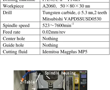
Drilling machine FANUC α-T14ics Workpiece A2060,50×80×30 ㎜
Drill Tungsten carbide,φ5.3 ㎜,2 teeth Mitsubishi VAPDSSUSD0530 Spindle speed 523~7600min-1
Feed rate 0.02mm/rev Center hole Nothing Guide hole Nothing
Cutting fluid Idemitsu Magplus MP5
3.実験結果
ドリルは回転しているため,特定の方向に曲が ることは考えにくいが,食いつき位置がずれると ドリル側面に抵抗が加わり,ドリルは位置ずれし た方向に曲がる7).食いつき位置のずれの原因と して,ドリル先端と回転中心のずれが考えられる. 本実験に使用したドリルの軸心と先端の同心度は 数ミクロン以内であり,チャックに取り付けた状 態でも回転軸との同心度は10μm以内である.と すれば,食いつき時の位置ずれもせいぜい10μm 程度でなければならないが,実際には10μm 以上 ある.もみつけをしても,食いつき位置が10μm 以上ずれることがある.これは,位置ずれの原因 がドリル先端の同心度だけではないこと意味して いる.また曲りの原因が食いつき位置のずれであ るとすれば,両者の間に相関関係がなければなら ないが,図 3 に示すようにばらつきが大きい.こ れは,食いつき位置のずれ以外にもドリルを曲げ るおおきな要因があることを示している.ドリル は回転しているため,XY 面内における切削抵抗 の平均値は0 になると考えられる.したがって, この現象を理解するには動的な要因,すなわち振 動を考慮しなければならない. ドリル加工でも再生びびり振動が生じることが 知られているが 8),ドリルの曲がりへの影響は報 告されていない.ドリル回転数の奇数倍の周波数 Accelerometer Kistler 8778A500spImpulse hammer Kistler 9722A500 Dynamometer Kistler 9257B
Fig. 1 Drilling machine
Table 1 Drilling equipment and condition Sample of table
X
Y
Z
Drill Workpiece X-Table Y-Table Z-Table Spindle HousingFig. 2 Measuring probe of hole position
Fig. 3 Relation between error of drill initial position and hole deflection Table 2 Measuring equipment of drill vibration
and cutting resistance
-60 -40 -20 0 20 -60 -40 -20 0 20 40 De fl e ct io n o f h o le μ m /1 5 m m
Error of drill initial position μm Measuring probe
Workpiece
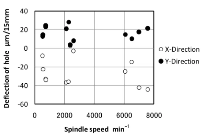
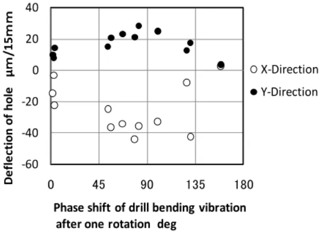
20 穴加工におけるドリル変形機構の解析 で再生びびり振動が生じる以外は,旋削における 再生びびり振動の発生メカニズムとおなじである. 奇数倍の周波数で再生びびり振動が生じるの は,2 枚刃の場合,ドリル半回転後の曲げ振動 が逆位相でなければ,再生効果が生じないため である.図 4 は,図 1 の加工装置に取り付けた ドリルの振動の周波数特性である. 48Hz の振 動はZ 軸テーブルの固有振動数であり,737Hz は主軸の固有振動数である.1738Hz はドリル の1 次モードの曲げ振動の固有振動である. 振動が穴の曲がりに影響する要因として2 つ考 えられる.ひとつは再生びびり振動である.図 5 はドリル食いつき時のドリルに加わる切削抵 抗のXY 面内における軌跡である.星型の軌跡 になっており,ドリル1 回転当り 5 周期の再生 びびり振動が生じていることがわかる. 図 6 は15mm の深さにおける切削抵抗の軌跡で あり,5 角形になっている.これも 5 周期の振 動であるが,振動の振幅は小さくなっている. 再生びびり振動では1 周期毎に位相ずれが生じ, 1 周期の切削抵抗の積分値が 0 にならない. このため,ドリルを曲げる力の平均値が0 にな らず,特定の方向に穴が曲がると考えられる. 図 7 にドリル回転数と穴の曲がりの関係を示 す.曲がりの正負は図 1 の加工装置の座標の正 負にしたがっている.回転数と曲がりの間に明 確な相関関係がないことわかる. しかし図 8 に示すように,ドリル曲げ振動の1 回転後の位相差と曲がりの間に相関関係があり, 位相差が90 度のとき曲がりが最大になり,0 度と180 度で小さくなっている.位相差はドリ ル回転数と曲げ振動の固有振動数で定まる値で あり,入力値である.これにたいして,穴の曲
Fig. 4 Frequency character of drill vibration
Fig. 6 Trajectory of cutting resistance at 15mm-depth
Fig. 7 Relation between spindle speed and hole reflection
-15 -10 -5 0 5 10 15 -15 -10 -5 0 5 10 15 Cu tt in g re si st an ce o f Y -d ir e ct io n N
Cutting resistance of X-direction N
0 0.2 0.4 0.6 0.8 1 0 500 1000 1500 2000 2500 A cc e le ra ti o n /F o rc e m m /s N Frequency Hz 2 1738Hz 737Hz 48Hz -60 -40 -20 0 20 40 0 2000 4000 6000 8000 De fl e ct io n o f h o le μ m /15 mm
Spindle speed min
X-Direction Y-Direction
-1
Fig. 5 Trajectory of cutting resistance at initial position Spindle speed: 754min-1
21
The Bulletin of Institute of Technologists, No. 3
がりは入力に対する結果である.本実験はドリ ル回転数だけを変化させており,他の実験条件 は表1の通り,一定である.またドリル回転数 の変化に伴う図4 の各種固有振動との位相ずれ は,ドリルの曲げ振動以外,相関関係が認めら れない.したがって,ドリルの曲げ振動が穴の 曲がりに大きく影響していると推定される. もうひとつのドリルを曲げる原因は,XY 方 向の振動のモードカップリングや非線形性にあ ると考えられる.図 9 はドリルにインパルス力 付加直後の振動加速度の軌跡である. X 方向に加振しているにもかかわらず Y 方向に 動いたりし,斜め方向の振動が目立つ.これは 振動のモードカップリングと非線形性に起因し ており,特定の方向に振動しやすいことと,振 動が非対称であることを示している.図 10 は ドリルにインパルス力を加えた後,5~10ms 後 のXY 座標上の加速度の軌跡である.加振方向 に拘わらず,一定の方向に振動していることが わかる.これはモードコンプライアンスの影響 で特定の方向の振動が残留していることを示し ている. ドリルの食い付き位置と深さ15mm における 穴位置誤差のXY座標を図 11 に示す. 右下の点が食い付き位置の誤差で,左上の座標 が深さ15mm における誤差である.左上に向か って曲がっており,図 9,図 10 の振動方向とお およそ一致している. この結果より,振動が穴の曲がりに影響して
Fig. 8 Relation between hole reflection and phase shift of drill bending vibration after one rotation
-150 -100 -50 0 50 100 -50 0 50 100 150 A cc e lr e ra ti o n o f Y -d ir e ct io n m /s Acceleration of X-direction m/s2 -10 -5 0 5 10 -10 -5 0 5 10 A cc e lr e ra ti o n o f Y -d ir e ct io n m /s Acceleration of X-direction m/s2 -60 -40 -20 0 20 40 0 45 90 135 180 D e fl e ct io n o f h o le μ m /1 5 mm
Phase shift of drill bending vibration after one rotation deg
X-Direction Y-Direction -10 0 10 20 30 -60 -50 -40 -30 -20 -10 0 10 20 Er ro r o f h o le p o si ti o n in Y -c o o rd in at e μm
Error of hole position in X-coordinate μm
Initial position 15mm-Depth
Fig. 11 Error of drill position at initial point and 15mm-depth Fig. 10 Trajectory of drill acceleration at 5~10ms
after impact with impulse hammer