Effective Water-Dispersed Surface Modified Carbon Nanomaterials by Ozone and Plasma Treatments
オゾンおよびプラズマ処理により表面改質したカーボンナ ノ材料の効果的な水分散
51426301
ZAW LIN
Division of Industrial Innovation Sciences
Graduate School of Natural Science and Technology
OKAYAMA UNIVERSITY
This dissertation is submitted for the degree of Doctor of Engineering
2017, September
D
ECLARATIONThe material presented in this thesis is the outcome of my own research under the supervision of Professor Yasuhiko HAYASHI at Okayama University. It has not been previously submitted, in part or whole, to any university or institution for any degree or other qualification.
Signed: ______________________________________________________________
Name: Zaw Lin
Date: 2017.8.22
ii
Abstract
Carbon nanomaterials (CNMs) have attracted much attention as promising materials for next generation nanotechnologies. Especially, carbon nanotubes (CNTs), carbon nanohorns (CNHs), and graphene have attracted enormous interest from the materials research community due to their combination of excellent electrical, optical and mechanical properties. Although these materials have unique properties, there are some limitations to realize in widespread applications. Achieving stable aqueous dispersion is one of the main challenges for wide applications. Several research groups have been reported to overcome this obstacle. Almost all of researches have been reported the methods using surfactants or chemical reagents. Consequently, the introduction of residual impurities, difficulties to the handling of waste products, and structural damage were observed to some extent. There is a crucial demand to develop an efficient and eco-friendly method to improve the dispersibility of CNMs.
This thesis is a study of the surface modifications of the most useful CNMs such as multi-walled CNTs (MWCNTs), CNHs, and multilayer graphene (MLG) for the effective dispersion in water. Innovative ozone and plasma treatments were used to achieve well-dispersed selected CNMs. Dielectric barrier discharge (DBD) system built with inverter-type alpha neon transformer and quartz tube was used for the generation of ozone and helium plasma. Firstly, the effect of ozone treatment on water dispersibility of micrometer orders long MWCNTs was studied. Commercial grade oxygen was used as a gas source and the ozone treatments were performed in the liquid phase and the combination of gas and liquid phase conditions. The well-dispersed MWCNTs were obtained in both treatment conditions with slightly better homogeneous in liquid phase treated sample. The characterization results show that MWCNTs were functionalized with oxygen and hydrogen containing groups that responsible for better
iii
dispersion. The dispersed MWCNTs were observed as stable dispersions even after three months.
The outcomes of helium plasma and ozone treatments on the dispersibility of CNHs in water also were investigated. After being treated with ozone, the oxygen- containing functional groups were introduced to the surface of CNHs and enhance the dispersion. The repulsive electrostatic forces between negatively charged functional groups are responsible for better dispersion. It was also found that the sizes of CNHs aggregates in water became smaller after ozone treatment. The dispersed CNHs modified by ozone treatment were stable for more than three months without precipitation. Helium plasma treatment was performed separately and it resulted in hydroxyl functional groups on the surface of CNHs. Although helium plasma treatment introduced hydroxyl groups to the surface of CNHs, the dispersibility decreased and the aggregation of CNHs was observed in a few minutes after treatment.
An innovative method for exfoliation and dispersion of MLG without using any chemical reagents or organic solvents were also presented as an important effort in this work. This was achieved by the ozone-assisted sonication of the natural graphite in a water medium. The heat generated by the dissipation of ultrasonic waves was used as it is, and no additional heat was supplied. The experimental setup is unique for ozone treatment and enables the elimination of ozone off-gas. It was found that, the dispersibility of MLG was greatly depended on the number of ozone treatment. The intermittent ozone treatment method, 6 times of 10 min, was achieved better dispersion than 1 h continuous ozone treatment in the same sonication time. The characterization results show that well-dispersed MLG was successfully synthesized without any significant damage to the overall structure. The dispersed MLG was centrifuged at 3000 rpm for 20 min, and relatively high concentration, 0.12 mg/ml, was achieved. The graphene dispersion was stable, and no evidence of aggregation was observed even after
iv
several months. The graphene obtained by this method has potential applications in composite materials, conductive coatings, energy storage, and electronic devices.
The efforts in this thesis have achieved well-dispersed selected CNMs through efficient and eco-friendly methods. Eliminating the use of chemical reagents or surfactants is significant of the work. It will greatly contribute to the applications of CNMs in the various fields. The experimental setups and surface modification techniques might be useful not only for CNMs but also other engineering materials.
v
Table of Contents
Abstract ……….. iii
Contents ………..……… vi
Chapter 1 Introduction 1
1.1 Research background ………. 1
1.2 Purpose of the study ………. 2
1.3 Organization of the thesis ………. 3
Chapter 2 Carbon Nanomaterials 4
2.1 Carbon nanotubes ……….. 4
2.2 Carbon nanohorns ……….. 9
2.3 Graphene ………. 11
Chapter 3 Dielectric Barrier Discharge (DBD) for the Generation Atmospheric Pressure Plasma and Ozone 15
3.1 Introduction ……… 15
3.2 DBD for the generation of atmospheric pressure plasma ……… 16
3.3 DBD for the generation of Ozone ……… …….. 19
Chapter 4 Dispersion of Relatively Long Multi-walled Carbon Nanotube in Water using Ozone Generated by Dielectric Barrier Discharge 22
4.1 Introduction ……… 22
4.2 Materials and methods ……… 23
4.2.1 Materials ……….. 24
4.2.2 Methods ……….. 25 vi
4.3 Results and discussion ………. 25
4.3.1 Fourier Transform Infrared Spectroscopy Analysis ……… 26
4.3.2 Raman Spectroscopy Analysis ………. 28
4.3.3 Transmission electron microscopy analysis ………. …. 31
4.4 Conclusions ……… 34
Chapter 5 Surface Modification of Carbon Nanohorns by Ozone and Plasma Treatments 36
5.1 Introduction ……… 36
5.2 Experimental details ………. 37
5.2.1 Materials ……….. 37
5.2.2 Ozone treatment of CNHs ……….. 37
5.2.3 Helium plasma treatment of CNHs ……… 38
5.2.4 Characterization ………. 39
5.3 Results and discussion ……… 39
5.4 Conclusions ……… 51
Chapter 6 Simple Technique of Exfoliation and Dispersion of Multilayer Graphene from Natural Graphite by Ozone-assisted Sonication 52 6.1 Introduction ……… 52
6.2 Materials and methods ……… 53
6.2.1 Materials ……….. 53
6.2.2 Experimental setup for the ozone treatment ……….. 54
6.2.3 Graphite exfoliation by sonication ………. 55
6.2.4 Characterization ………. 56
6.3 Results and discussion ………. 57 vii
6.4 Conclusions ……… 67
Chapter 7 Conclusions and Future Work 68 7.1 Conclusions ……… 68
7.2 Future work ……… 70
Acknowledgments ………. 71
References ………. 72
List of publications ……….……….. 82
viii
CHAPTER 1 Introduction
1.1 Research Background
Carbon nanomaterials (CNMs) have become promising candidates for numerous applications due to their extraordinary properties [1,2]. Especially, CNTs, CNHs and graphene have attracted enormous interest from the materials research community due to their combination of excellent electrical, optical and mechanical properties [2].
However, there are practical issues concerning the utilization of the carbon nanomaterials due to their poor dispersibility in a variety of the matrixes and solvents including water medium. There is a crucial demand to develop an efficient and eco- friendly method to improve the dispersibility of carbon nanomaterials in the target medium.
Difficulties in the dispersion of CNMs originate from their tendency to aggregate due to the van der Waals attractions and hydrophobic interaction between CNMs. The presence of agglomeration in the medium is the source of the potential defect and may also be adversely effected on the materials properties [3]. Numerous surface modification and functionalization techniques have been used to address such challenges in the aggregation of CNMs [4-6]. Most of the reported methods were used chemical reagents and surfactants. Even though these methods had proved the improvement in the dispersion of CNMs, introduction of residual impurities, difficulties to the handling of waste products, and structural damage are still challenging.
Surface modification of CNMs by various types of plasmas has been used to reduce the agglomeration [7]. Plasma treatments generally introduce functional groups which electrostatically prevent agglomeration and can also enhance interactions with the target medium. These methods range from low pressure plasmas to atmospheric plasmas
1
using various gas sources. Most of the plasma generation devices are complex, expensive and need special skill to operate. As an alternative, Ultraviolet-Ozone (UVO) treatments of CNMs have been reported [8,9]. This method has many advantages such as equipment and operating cost are relatively low, environment-friendly and induce chemical functionality without changing their unique characteristics. Ozone reacts only exposed surface and hence the CNMs maintain their intrinsic structures. However, the designs and sizes of UVO devices are fixed and difficult to adapt based on the samples containers. In addition, there is no function to stir the samples for well-exposing with ozone.
1.2 Purpose of the Study
The applications of CNMs in different fields are greatly promising due to their unique physical and chemical properties. Among these materials, CNTs, CNHs, and graphene have attracted enormous interest from the materials research community due to their combination of excellent electrical, optical and mechanical properties. However, there are practical issues concerning the utilization of the CNMs in various fields such as polymer composite, a conductive film, nanofluids and electronics applications. Most of these difficulties are related to the poor dispersibility of the CNMs in a variety of the matrixes and aqueous media. Dispersion of CNMs in water can cause them fulfills the challenges for several applications.
Many research groups have been reporting to overcome this challenge.
Nevertheless, most of the reported methods have used the chemical reagents and surfactants. The limitations of these methods are difficulties of handling and producing of harmful waste products, expensiveness, and introducing of the impurities into the structure. There is a demand to develop an efficient and eco-friendly method for dispersion of carbon nanomaterials.
2
The main purpose of this thesis is attempting to get well-dispersed CNMs (CNTs, CNHs, and MLG) without using any chemical reagents or surfactants. In addition, an inspiration to develop new synthesis method to achieve well-dispersed multilayer graphene is one of the objectives. Moreover, innovations of experimental setups that use simple and flexible ozone and helium plasma generation systems are also important parts of this work.
1.3 Organization of the Thesis
The chapter contents of this thesis are briefly described as follows;
Chapter 1 includes the brief description of the research background, the purpose of the study and organization of the thesis.
Chapter 2 reviews on the various CNMs with focused on CNTs, CNHs and graphene materials.
Chapter 3 briefly describes the DBD system designed to generate ozone and plasma for various applications.
Chapter 4 presents the attempting to disperse the relatively long MWCNTs in water using ozone generated by DBD, and the characterizations and related results of the ozone treated samples.
Chapter 5 mentions about the surface modification of CNHs by ozone and helium plasma treatments. The various characterizations and related results are shown to understand the effect of surface treatments.
Chapter 6 begins with the description of various graphene synthesis methods and challenges of the present situations. Subsequently, a simple and eco-friendly method is described to synthesize well-dispersed MLG.
Chapter 7 includes the conclusions that cover for all research works and the suggestions for the future work.
3
CHAPTER 2
Carbon Nanomaterials
Carbon is well known for diverse structures and properties ranging from sp3 hybridized diamond to sp2 hybridized graphite. Depending on how the carbon atoms are arranged, different ranges of properties are exhibited. In the last decades, the different carbon nanomaterials such as nanotubes, nanohorns, graphene, fullerenes and diamond- like carbon attracted enormous interest in the scientific community due to their potential use in a broad range of applications.
2.1 Carbon nanotubes
CNTs were discovered by Japanese physicist Professor Sumio Iijima, NEC Corporation in 1991 [10]. He discovered this material during Transmission Electron Microscopy (TEM) observation of soot generated from the electrical discharge between two carbon electrodes. Initial observation of Iijima’s work was multi-walled carbon nanotubes (MWCNTs). Single-walled carbon nanotubes (SWCNTs) were discovered after one year of MWCNTs observation by Iijima and his group at the NEC laboratory and Don Bethune et al [11,12]. These findings have more impact on the development of CNT because of SWCNTs is more fundamental and the basis for theoretical studies.
CNTs are one-dimensional tubular nanostructure of carbon allotropes. They have a high aspect ratio and, a few nanometers in diameter and many micrometers long [13].
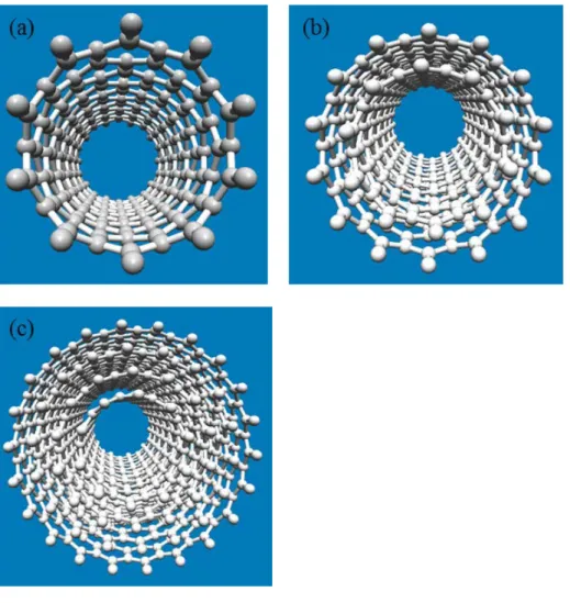
Depending on the number of layers, CNTs can be categorized as single-walled, doubled-walled and multi-walled CNTs as shown in Fig. 2.1 [14]. The sidewalls of the CNTs are composed of a hexagonal lattice of carbon atoms and are capped at both ends by one-half of a fullerene-like molecule. Theoretically, CNTs is stronger than steel due
4
to the strong sp2 bonds between the individual carbon atoms [15]. This bond is even stronger than the sp3 bond found in the diamond structure.
Figure 2.1 Classification of CNTs (a) SWCNT (b) double-walled CNT and (c) MWCNT
There are varieties of techniques that have been developed for the production of CNTs. The most common techniques are the chemical vapor deposition (CVD), the laser ablation and arc discharge techniques [16]. In the CVD method, there are many different types such as catalytic chemical vapor deposition (CCVD), plasma enhanced CVD (PECVD), water assisted CVD, etc. Among these techniques, CCVD is the standard technique for the synthesis of CNTs.Using these methods, CNTs are produced
5
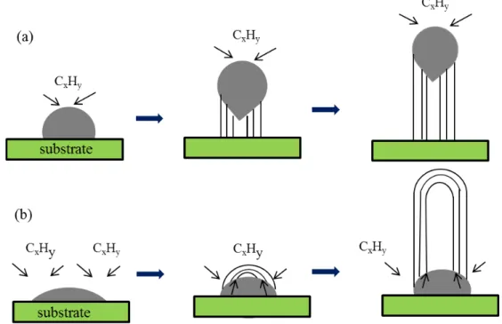
from the gaseous carbon source. The gas source decomposes at elevated temperature and passes over a metal catalyst of Fe, Co or Ni, etc. There are many advantages of the CVD method. For example, the product tends to be purer, and the growth occurs at a relatively lower temperature of about 600 ºC. In addition, the metal catalyst can be placed on a substrate, which can lead to the growth of aligned nanotubes in the desired direction with respect to the substrate. The schematic mechanism of CNTs synthesis on the substrate is shown in the Fig. 2.2 [17]. Figure 2.2(a) shows the “tip-growth model”, in which hydrocarbon decomposes on the top surface of the metal and diffuses down through the metal, and precipitates out across the metal bottom as CNTs. CNT continues to grow longer until the metal’s top is open for fresh hydrocarbon decomposition. In the base growth model, Fig 2.2(b), initial hydrocarbon decomposition and carbon diffusion take place similar to the mechanism of tip-growth model, but the CNT precipitation fails to rise up the metal particle; so the precipitation is grown out from the metal surface.
Figure 2.2 Schematic growth mechanisms of CNT (a) Tip-growth model and (b) base-growth model
6
A high power laser, usually Nd: YAG was used in the laser ablation technique to vaporize carbon from a graphite target. There are several parameters that influence the quantity and quality of produced carbon nanotube, such as the amount and type of catalysts, laser power and wavelength, temperature, pressure, and type of inert gas. The purity of carbon nanotubes produced by laser ablation is over 90 % and has a relatively narrow distribution of diameters. The arc-discharge technique uses higher temperatures (above 1,700°C) for CNT synthesis which usually results in the growth of CNTs with fewer structural defects in comparison with other methods. Arc discharge system consists of a furnace, a stainless steel vacuum chamber, graphite electrodes, a water- cooled trap and high voltage power supply. This method utilizes the arc discharge between high-purity graphite electrodes usually water-cooled electrodes with diameters between 6 and 12 mm and separated by 1 to 2 mm in a chamber filled with gas (helium or hydrogen or methane) at sub-atmospheric pressure.
Owing to their inert nature, the CNTs tend to form bundles with each other and thus do not disperse well in water or organic matrices as well as poorly chemically compatible with the polymer matrix in their pristine state. It is difficult to prepare stable aqueous dispersions of CNTs and hence, it has been a limitation for the practical applications in various fields. Suitable surface modification or functionalization of the CNTs is thus vital in order to optimize their dispersion in various media.
There are several approaches have been taken to enhance dispersion of CNTs such as chemical oxidation, surfactant adsorption, and polymer wrapping [18]. Among these methods, chemical oxidation or covalent functionalization is the most common method for surface modifications, which enables the formation of oxygen-containing functional groups on the CNT surface and hence improves the dispersibility. These functional groups take place at the end and on the walls of CNTs; most of the methods are available both in solution and in the gas phase. Several oxidants are available in this
7
method such as HNO3, H2SO4, KMnO4, and H2O2. The different oxygen-containing functional groups are formed on the surface such as COOH, C=O, C-O, and OH. The relative percentage of oxygenated groups on the surface of CNTs depends on the chemical reagent and the experimental conditions. Surface modification using surfactants enhance the water dispersibility of CNTs due to the formation of a coating on the surface. Among the surfactants, sodium dodecyl sulfonate (SDS), and sodium dodecylbenzene sulfonate (SDBS) were commonly used as surfactants [19]. Surface wrapping with long polymer chains such as polystyrene sulfonate and noncovalent adsorption of polymer chains such as polyvinyl pyrrolidone also can improve the dispersibility of CNTs in several media. Recently, many polymer dispersants have been developed for dispersion of CNTs. This method is currently incapable of enduring stable water-based dispersion of CNTs due to the reaggregation over a prolonged time.
Ozone oxidation both in gas and liquid phase can improve the dispersibility of CNTs. In addition, ozone treatment has been successfully applied to the elimination of amorphous carbon in purification processes, to open closed tips and sidewalls of nanotubes as well as to facilitate functionalization on the CNTs surface. UV ozone oxidative process has also been used to realize CNTs functionalization. Plasma treatment is an efficient method to modify the surface properties of various materials. There are several types of plasma techniques have been applied to improve CNTs dispersibility. Compared to other chemical modification methods, this method has the advantages of shorter reaction time and environmentally friendly. Owing to the proper surface hydrophilic groups is introduced onto CNTs surfaces, it is expected that the plasma treated materials can provide a strong affinity to interact with other materials and enhance dispersion in the aqueous medium.
8
1.3.1 Carbon Nanohorns
CNHs are single-walled tubules with a horn-shaped tip, named by Sumio Iijima in 1999 [20]. According to their morphologies, there are three different types of CNHs;
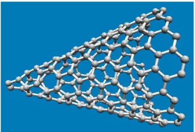
dahlia-like, bud-like, and seed-like. In the dahlia type, the CNHs protrude from the aggregate surface, while CNHs appear to develop inside the structure itself in the other types. The schematic conical structure of CNH is shown in Fig. 2.3. Most of the CNHs have the diameter of 2-5 nm, tubule length of 15-50 nm and a cone angle of approximately 20º [21]. A few thousand of CNHs form as a spherical aggregate with a diameter of 30-100 nm [22]. CNHs are usually composed of single graphene-like SWCNTs; however, there are no multi-walled CNHs by far. As-produced CNHs are closed tubes and their specific surface area can be increased by opening the holes.
The unique structure with high surface area and microporosity are very attractive properties of CNHs. The opening of holes in pristine CNHs by heat treatment or chemical oxidation increases the surface areas and the pore volumes. As grown CNHs exhibit semiconducting properties and the electrical conductivity increases with temperature.Thin layer coating of CNHs has good field emission characteristics of low turn-on field and high long-term stability.
The applications of CNHs are mostly relating the capability to adsorb gases or other materials. CNHs have been interested as novel candidates for gas storage system due to the gas molecules can be stored in both the cylindrical inner nanospace and interstitial channels. Also, there are many promising application such as catalyst supports, a carrier for drug delivery system,photovoltaics, and biosensing applications.
9
Figure 2.3 Schematic conical structure of CNH
Synthesis of CNHs usually involves sufficient injection of energy to vaporize and restructure a carbon target, followed by rapid quenching, in an inert gas atmosphere [23]. Unlike CNT production, it is not necessary to use metal catalysts to produce CNHs. Consequently, pristine CNHs show high purity and no purification step is required for most of the applications. There are three common methods to synthesize CNHs depending on the technique used to inject energy into the carbon. They are arc discharge method, laser ablation method, and Joule heating methods [24].
In the arc discharge method, high purity CNHs is produced directly by a pulsed arc discharge between carbon rods in atmospheric pressure. Annealing is used to remove residual amorphous carbon in the dry air. For the large-scale production of CNHs, submerged arc discharge processes are more common. Arc discharge in water method can produce efficiently high purity CNHs. In the modified version, nitrogen or argon gas is injected into the arc zone via holes in the graphite electrode. The laser ablation method is utilized to produce the first CNHs at room temperature without using any metal catalyst. Dahlia flower like CNHs was first synthesized by pulsed laser ablation of graphite in an argon atmosphere with the relatively high rate. The size of the CNHs produced in this way is typically larger the size of those produced by arc discharge. The bud-like CNHs usually synthesize under lighter inert gas atmosphere
10
such as helium and nitrogen. Comparing to arc discharge, smaller CNHs are produced under a Neon gas atmosphere.
Single-walled carbon nanohorns (SWCNHs) belong to single wall nanocarbon family and have a similar structure with SWCNTs. Consequently, similar surface modification methods can be applied for the CNHs. In the noncovalent surface modification, various surfactant molecules are adsorbed on the surface of CNHs. In this case, the surfactant molecules are only physically bound to the surface. In the covalent means of surface modification, polymer chains can be grafted to the surface of the materials. Heat treatment in an oxygen atmosphere of as grown SWCNH can open the holes and increase the surface area and pore volume. Chemical doping can be applicable to increase the density of charge carrier and thereby enhance the electrical conductivity [25]. Different surface modification methods have their own advantages and disadvantages. Depending on the applications and required properties, the right choice of suitable modification methods is important.
1.3.3 Graphene
Graphene is a single atomic layer of graphite in which carbon atoms are arranged in a two-dimensional honeycomb-shaped lattice as shown in Fig. 2.4 [26]. Professor Andre Geim and Kostya Novoselov belong to Manchester University discovered graphene in 2004. They demonstrated that the single layer graphene was successfully produced by peeling off the graphite with scotch tape. Since then, graphene has attracted to the scientist and researcher and became an exciting topic. They won the Nobel Prize in physics for the year 2010 due to the finding of graphene.
Graphite has a layered structure and composed of the millions of the graphene layers. Basically, graphene structures are formed by the Vander Waal and covalent bonding between the graphene layers. Vander Waal bonding holds together the layers of
11
graphene by the weak force. Owing to the weak attraction between layers, the layers slide each other to exfoliate into individual layers. A covalent bond is formed between the carbon-carbon atoms in each layer. Each carbon atom in graphene is hybridized as sp2, 2s with 2px and 2py, and bonded to three other neighboring carbon atoms. The remaining free 2pz orbital is overlap between neighboring atoms and perpendicular to the plane of the carbon atoms. Multilayer graphene can have a number of stacking arrangements; Bernal stacking (ABAB) and Rhombohedral stacking (ABCABC) are the typical [27]. The atomic structure of graphene is a basic structure of other carbon-based materials such as fullerenes, carbon nanotubes.
Graphene is the strongest and lightest material ever known and exhibit excellent electrical conductivity. In addition, high carrier mobility and specific surface area, and outstanding optical characteristic are also fascinating characteristics of graphene. Owing to these unique properties, graphene has many potential applications in various fields, such as composite materials, conductive thin film, and energy storage and electronics devices.
Figure 2.4 Schematic structure of graphene
Graphene synthesis can be classified into two approaches as top-down and bottom-up [28]. In the top-down approaches, the stacked layers of graphite were broken
12
apart into separated graphene sheets. In contrast, the bottom- up approaches involve the deposition of graphene from alternative carbon-containing sources. Several synthesis methods have already been reported for graphene materials. The most common methods are liquid phase exfoliation (LPE), reduction of graphene oxide, electrochemical exfoliation micromechanical exfoliation, and chemical vapor deposition. Also, arc discharge method, graphite intercalation, epitaxial growth, and unzipping of CNTs were some of the important graphene synthesis methods. The quantity, quality, and form of graphene obtained are varied depending on the synthesis methods. Each method has its own advantages and disadvantages that need to choose suitable method according to the applications and facilities. The LPE is a straightforward and scalable method to synthesize defect-free graphene. This method is unique due to the minimal defect concentration and low oxygen functional groups at the obtained graphene product.
Several studies of LPE have been reported to synthesize dispersed-graphene in common chemical solvents with or without surfactants by the assist of ultrasonication. The most common solvents are N-methyl-2-pyrrolidinone (NMP), dimethylformamide (DMF), Dimethyl sulfoxide (DMSO), and Ortho-dichloro benzene (ODCB). In addition to this, the mixture of alcohol groups and water also one of the important solvents to exfoliate graphene. However, some issues such as poor stability, long sonication periods, low concentration, expensive solvents and the excessive use of surfactants are limiting factors for wide applications. Moreover, toxicity and high boiling points of solvents also facing the challenges because of making it difficult to remove and handle the residue after the process. Alternatively, graphene can be exfoliated in aqueous media and eliminates some of the limitations of using solvents. Nevertheless, stabilizer or surfactants are necessary to maintain the stability of exfoliated graphene In this case; the head-group of the surfactant interacts with the liquid environment and prevents the graphene sheet from reaggregation by electrostatic repulsion. The most common
13
aqueous surfactants include sodium cholate, sodium dodecyl benzyl sulfonate (SDBS), sodium dodecyl sulfate (SDS) as anionic surfactants, cetyltrimethylammonium bromide (CTAB) as a cationic surfactant. Adding surfactants might introduce the impurities and decrease the intrinsic properties of graphene. Chemical reduction of graphene oxide (GO) is one of the conventional methods to synthesize graphene in large quantities. In this method, GO is usually synthesized through the oxidation of graphite using oxidants including strong acid and potassium based on Brodie method, Hummers or modified Hummers method [29]. Popular reducing agents are hydrazine, hydroxylamine, and alkaline solutions. Electrochemical reduction is an another mean to synthesize graphene in an electrolysis system. This method is fast, eco-friendly, and non-toxic solvents are used. Consequently, the amount of contamination reduces significantly compared to conventional methods. Mechanical exfoliation is a process for extracting graphene flakes on preferred substrates. This method is the first recognized method to synthesize graphene by scotch tape. Graphene sheets of different thickness can be achieved by peeling off layers from graphitic materials such as highly ordered pyrolytic graphite (HOPG), single-crystal graphite, or natural graphite flakes [30]. Chemical vapor deposition (CVD) method can produce relatively high-quality graphene using precursor carbon gaseous sources. Although CVD process needs some relatively complex equipment, it is reasonably straightforward and can synthesize good quality graphene.
During the high-temperature CVD process, a substrate is diffused on thermally disintegrated precursors and deposits on the substrate. This process is usually done onto various transition metal substrates such as Ni, and Cu. There are several other ways have been reported graphene such as epitaxial growth, arc discharge unzipping of CNT, plasma enhanced CVD. On the other hand, scientists have been developing more efficient and eco-friendly techniques in order to create the highest quality of graphene.
14
CHAPTER 3
Dielectric Barrier Discharge for the Generation of Atmospheric Pressure Plasma and Ozone
3.1 Introduction
DBD is the self-sustaining electrical discharge between two electrodes separated by an insulating dielectric barrier. First experimental investigations of DBD were reported by Siemens in 1857 [31]. In the beginning, this method was used for the generation of ozone and opened up many other fields of application such as surface treatment, degradation of pollutant molecules in gases, generation of excimer radiation and plasma [31,32].
Depending on the application, several different DBD reactors or device designs could be used. The classical reactors for ozone generation from air or oxygen are cylindrical devices with coaxial electrode arrangement. The dielectric materials are used either as the outer electrode or covering the inner electrode. Several kinds of electrodes such as metallic film deposited or pasted on the inner and/or outer dielectric tube, metal wire, and copper tape. Typically, glass, quartz, ceramics, mica, plastics, silicon rubber or teflon are used as dielectric materials.
Type of power supplies units plays the important role in the development of DBD system. A high voltage sinusoidal AC power supply has been used for the research and industrial usage. The pulsed or radio frequency driven discharges also has been studied since the last two decades. Power supplier of the frequency either MHz or GHz range has been used for plasma experiments. In this case, the electrical power is injected by electromagnetic wave form. Recently, simple and efficient power suppliers for lightening the neon tube; i.e., the neon transformer was developed using the modern inverter technology and can be available with less expensive. Using the neon
15
transformer, we can obtain the kHz range and kV range electrical power with ease. The supplied voltage can be tuned by the input voltage using a variac. The compact power source devices that can eliminate bulky high-voltage transformers is also an important factor to realize DBD system in various applications. The inverter type alpha neon M-5 transformer is shown in the Fig. 3.1.
Figure 3.1 Photograph of Inverter type alpha neon M-5 transformer
3.2 DBD for the Generation of Atmospheric Pressure Plasma
Plasma is an ionized gas consisting of atoms, molecules, and approximately equal numbers of positively charged ions and negatively charged electrons [33]. It is known as the fourth state of matter due to the different characteristics of plasmas from those of ordinary gases. According to the pressure, there are two main types of plasmas, atmospheric pressure, and low pressure [34]. Within atmospheric-pressure plasmas, it can be divided into two categories, thermal and nonthermal. In thermal plasmas, electron temperature, and heavy particles temperature are approximately same. The temperature of core gas in thermal plasmas has over 10,000 K and the gas is significantly ionized [35]. The atmospheric pressure nonthermal plasma has very high electron temperature while the heavy particles temperature or sensible temperatures
16
remain ambient. In this type, the electrons and ions never occur at local thermodynamic equilibrium and hence the gas is at room temperature. This kind of plasma is very reactive due to the existing of the high density of activated species, i.e. reactive free radicals, and excited state atoms. Chemically reactive atmospheric pressure plasma discharges are widely used to modify the surface properties of materials. They are used in electronic industry, metallurgical applications, nanomaterials synthesis, refractory and wear resistant coatings deposition, energy conversion, medical applications., etc.
There are various methods to generate atmospheric pressure plasmas, such as DBD, microwave discharge, radio frequency discharge, and direct current discharge [36]. These methods have their own unique features that are suitable for relevant applications. The DBD, atmospheric pressure plasma jets (APPJs), is the most promising discharge candidate for the surface treatment of various materials including carbon materials because of their ability to generate a high flux of different metastable active species [32,37]. This method does not require a vacuum facilities and that makes for the building of compact and low-cost plasma sources. The DBD system consists of two flat metal electrodes that are covered with quartz or other dielectric materials [38].
A carrier gas moves between the two electrodes and is ionized under high applied voltage and kHz range frequencies to create a plasma. Helium, argon, and oxygen are the most commonly used as a gas source for plasma generation. The system usually uses low ampere level and consequently, the power consumption is just less than 100 W. The free electron density of DBD plasmas have approximate 1010 electrons per cm3 and a power density of about 0.1 W/cm3 [39].Several different variations in the configuration of the electrodes and system design are used for different purpose, but the concept behind them remains the same. For example, some systems use cylindrical electrodes instead of flat and the dielectric material covers only one electrode instead of both.
Apart from DBD, corona and glow discharge also can generate plasmas. However, the 17
electric current density is low, and the discharge is inhomogeneous in corona discharge, and so a plasma jet cannot be formed. In this discharge, the free electron density is approximately 108 electrons per cm3 and usually has low power density [40]. In the glow discharge method, plasma is formed by the passage of electric current through a low-pressure gas, which cannot be adapted to generate a plasma jet. Glow discharges generate plasmas by applying relatively low voltage, a few hundred, with high MHz range frequency [41].
The atmospheric pressure plasmas have found wide applications due to their combination of simplicity, low cost, and wide possibilities for surface treatment and modification of various materials. Plasma treatment for surface modification is mainly used to clean and produce the hydrophilic surfaces on carbon nanomaterials, semiconductor, metals, glasses, polymers and their composite materials [42]. The plasma can also be used effectively for materials processing and suitable for materials sensitive to thermal damage. The quality of surface coating improves by using plasma treatment. Surface modification by plasma could be used to improve the electrical and optical properties of oxide films grown by other methods. Moreover, it can be used for the post-deposition annealing of ITO coatings. Plasma treatment of the ITO coatings significantly improved their electrical and optical properties due to additional oxidation, recrystallization, and reduced defect density. The hydrophilic modification of inactive polymeric surface can be performed by atmospheric pressure plasma especially DBD discharge has been widely used in research and manufacturing industries. Owing to the numerous active radicals it significantly raises the surface energy and improves the wettability. Plasma treatment makes leaving free radicals on the surface of materials and allowing it for bonding. In contrast to typical hydrophilic modification, the hydrophobic surface modification is also another useful application for the manufacturing industry such as micro inkjet printing, corrosion protection, self-cleaning surfaces etc. High flow
18
rate of fluorocarbon compounds such as CF4, C4F8 or NF3 and SF6 have been often used to get those hydrophobic surface conditions [43].
A quartz tube with an inner diameter of 3.5 mm and a length of 150 mm was used as the dielectric material. The converter type Alpha Neon M 5 transformer was used for helium plasma generation, where applied frequency was modulated from 60 Hz to 20 kHz with a 7 kV peak to peak value and a peak current of 20 mA which corresponds to an effective current of 10 mA. It is noted that the effective values of the voltage and the current become half that of the peak values if the applied waveform is a superposition of two sinusoidal waves. Copper tape was wound around the quartz tube at two places as electrodes and kepton tape of 10 mm width was wound between two copper tape electrodes to prevent electric arcing. The photograph of helium plasma plume was shown in Fig. 3.2.
Figure 3.2 Photograph of helium plasma plume
3.3 DBD for the Generation of Ozone
Ozone is a powerful tool in surface modification of carbon, glass, polymers and many other materials [44]. The existing of ozone was reported by the Dutch scientist Van Mauren in 1785 whilst he was experimenting with an electrical machine [45]. It cannot be stored and transported like other gases due to the quick decay into oxygen and therefore be produced and used on the site. Ozone treatment of carbon materials is the cleanest, solvent free, simplest and effective way to introduce oxygen-containing
19
functional groups on the surface. Natural ozone is found in the stratosphere known as the ozone layer. The lightning and UV radiation effect produce ozone naturally. It is a relatively unstable and strong oxidizing gas. The usage of ozone shows an important progression in the various fields such as wastewater treatment, sterilization, and deodorization, etc. It is a natural oxidizing gas, which does not use chemicals and leaves no harmful chemical residue and hence, the most healthy and effective alternative to chemicals.
Generally, there are three common ozone generation methods; DBD, corona discharge, ultraviolet radiation [46]. Energy supply is necessary to break the oxygen bond and allowing them to dissociate and then re-form as ozone. The DBD method has been widely used for generation of ozone with a concentration of about 5 to 20 %. In this method, pure oxygen takes place between two electrodes which are separated by a dielectric material (insulating barrier). When the energy is applied and an electric field is formed, oxygen molecules are split into single oxygen atoms, one of which then recombines with O2 and forms ozone. This method produces not only ozone but also activate radicals and excited species such as O, H, and OH, which are generated by dissociation and ionization of the feed gas or ambient gases as a result of energy transfer from energetic electrons to the gas molecules.
The production of ozone by the corona discharge is a very common method. It produces ozone by channeling air into a corona discharge tube, where plasma is created by applying high voltage. The difference between the DBD and the corona discharge ozone generation method lies in the means used to create the plasma and the feed gas used. On the other hand, ozone can be generated by irradiation with an ultraviolet lamp.
Air or oxygen is passed over an ultraviolet lamp and the UV light splits oxygen molecules in the gas. The resulting oxygen atoms (O-) attach to other oxygen molecules (O2) and forming ozone (O3).
20
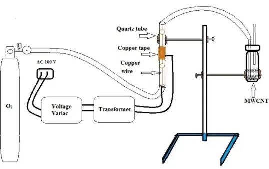
To construct the DBD system for ozone generation, the quartz tube with the following specifications was used: length (150 mm), outer diameter (8 mm) and an inner diameter (7 mm). The length of copper tape electrode that wounded the quartz tube was 50 mm and the inner copper wire electrode was 120 mm. That inner electrode was inserted into the tube from one end. Inverter type Alpha Neon M 5 transformer was used to step up the required voltages. A voltage variac was used to regulate the high voltage applied to the setup. Oxygen was used as a gas source to generate ozone.
Working on this ozone generation set up; the oxygen cylinder was connected to the quartz tube via Polytetrafluoroethylene (PTFE) or Perfluoroalkoxy alkane (PFA) pipe which connected to the gas flow rate regulator. Voltage was applied to the input side of the variac about 100V AC and the primary side of the transformer was connected to the output of the variac. Two wires were connected from the output of the transformer to the electrodes above and inside the tube to complete the basic circuitry. The open end of the tube is connected to a PFA pipe which was then fed to the glass bottle containing the sample. The tube set up was held firmly to a stand as shown in Fig. 3.3.
Figure 3.3 Photograph of the DBD system for ozone generation 21
CHAPTER 4
Dispersion of Relatively Long Multi-walled Carbon Nanotube by Ozone Generated by Dielectric Barrier Discharge
4.1 Introduction
CNTs have unique properties which are valued for electronic and electrochemical applications, reinforcement in composite, biomedical and many other device applications [47,48]. However, pristine CNTs have very poor dispersibility and solubility in water and most of other solvents[49]. Especially the larger aspect ratio or the longer length of nanotubes has the poorer dispersibility. Chemical inertness of CNTs has encountered difficulty in interaction with many matrixes [50]. Before realizing their applications it is required to overcome this challenge. In recent years the applicability of CNTs have been realized in few applications and to take it further, the properties need to be modified, hence more applications can be done in near future.
Although the wet chemical oxidation method can improve dispersibility, the generation of liquid wastes still limits their further developments of applications [51]. In addition to this limit, some reactions can cause severe damage to carbon nanotubes and degrade the properties of nanotubes. Meanwhile, non-covalent or physical treatment can decrease the conductivity of materials because they form an insulating layer [52], damaging the surface property of the carbon nanotubes. This treatment can preserve the intrinsic properties of carbon nanotube [53]. However, the requirement of a removing process for the resulted layer is still challenging and it is a time taking and complex process adding many steps in the process. Alternatively, the water solubility of carbon nanotube using polymer wrapping technique also has been demonstrated [54].
Nevertheless, these methods still have obstacles to get stable dispersion since they tend to aggregate over a prolonged period of time [55].
22
Ozone and plasma treatment of carbon nanotubes are the recent methodologies adopted for the functionalization and dispersion of carbon nanotubes [56]. Currently, many research papers have been published regarding the dispersion of single-walled carbon nanotubes [57-59]. Although these results are successful, they have certain limitations like the concentration of ozone used was high and time taken for the treatment was also long. In addition, these experiments have used fixed ozone generator design and not suitable for liquid phase treatment. Almost all reported research have been used UV-ozone and hence there is a space limit according to the design of ozone generator [8,9].
In this study, we have developed a simple ozone generation setup using the dielectric barrier discharge to instantaneously producing ozone from oxygen gas and treated the multi-walled carbon nanotubes simultaneously. The liquid phase and gas- liquid phase were used to treat the pristine MWCNTs which is a newer parameter in the research. Treatment of CNTs with ozone has a significant effect on the nature of the surface of materials that lead to the introduction of oxygen-containing functional groups.
4.2 Materials and Methods 4.2.1 Materials
MWCNTs were synthesized by thermal CVD technique using catalysts. In the process, a thermal CVD (“Black Magic II” by Aixtron Ltd.,) was used with substrates (Fe/Al2O3/SiO2/Si). A catalyst of Fe film and thin Al2O3 supporting layer were deposited on the SiO2/Si wafer by sputtering. Acetylene gas as a carbon source and hydrogen were used for CVD process. The growth of CNTs occurred as follows. First, iron particles formed by heating in a hydrogen ambient. Second, acetylene gas was supplied and carbon was incorporated in iron particles. Third, extracted carbon formed
23
CNTs around iron particles. The average diameter of the MWCNTs was 4 nm and the average length of the nanotubes was several micrometers. Pure water was used to disperse the MWCNTs. Detailed experimental set up for ozone treatment CNTs is shown in Fig. 4.1.
Figure 4.1 Experimental setup for ozone treatment of MWCNTs
4.2.2 Methods
For ozone treatment, the vial containing the samples was placed with the screw cap with the hole made to fit the PFA pipe and another hole was made to balance the pressure in the vial. The glass vial was placed firmly onto a stand clamp. The gas flow rate regulator was set to 1 l/min and the nozzle was turned on to allow the oxygen gas to flow at 1 l/min. The concentration of ozone at this flow rate was 84 ppm. Gastec No.18 M ozone detector tube was used to measure ozone concentration. The AC 100 V was supplied to the variac that regulates the input voltage for the neon transformer. The transformer is compacted and can steps up the voltage up to 9 kV maximum. The variac was set to 50 V to supply half of the maximum voltage ( 4.5 kV) and connected to the electrodes. The oxygen then converts into ozone by dielectric barrier discharge and was
24
allowed to pass into the glass bottle containing MWCNTs suspension. The experiments were conducted on different treatment conditions and times. The detail experimental conditions for all samples were shown in table 4.1. The pristine and well-dispersed samples (6 and 10) were taken for further characterization and denoted as sample (A, B and C). In sample A, 0.5 mg of pristine CNTs were taken in a clean glass bottle and sonicated without doing treatment for about 15 min. Same amount of samples and water 30 ml were taken for all treatments. In sample B, CNTs were treated in ozone gas phase only for 1 h and then treated again in water for 2 h; it became 3 h total treatment time.
The ozone treatment was done for 4h in the water medium only for sample C. All the samples have been conducted sonication for 15 min. The prepared samples were characterized by the HR-TEM, FTIR, and Laser Raman Spectroscopy.
Table 4.1 Experimental conditions of ozone treatment on MWCNTs Sample Weight
(mg)
Water volume
(ml)
Ozone treatment ( gas phase)
Ozone treatment ( liquid phase)
Dispersion conditions
Pristine 1 2 3 4 5 6 7 8 9 10
5 5 5 5 5 5 5 5 5 5 5
30 30 30 30 30 30 30 30 30 30 30
- 30 min
1 h 2 h 4 h 1 h 1 h - - - -
- - - - - 1 h 2 h 1 h 2 h 3 h 4 h
poor little little little little moderate
good little little moderate
good 25
4.3 Results and Discussion
The ozone treatment can modify and functionalize the surfaces of MWCNTs in both methods by using ozone generation set up. It can be clearly observed in Fig. 4.2 that the MWCNTs were not dispersed without ozone treatment. For sample B which has undergone ozone treatment in both gas phase and liquid phase looks like disperse slightly higher compared to sample C which has done treatment only in liquid medium.
The ozone treated CNTs were observed to be dispersed and stable for a few months after centrifugation. We used the Hitachi Himac CT6E tabletop centrifuge at 4000 rpm speed to sedimentation of the bundle.
Figure 4.2 Images of MWCNTs dispersion in water before and after ozone treatment: (A) pristine MWCNTs (B) 3h and (C) 4 h ozone treatment
4.3.1 Fourier Transform Infrared Spectroscopy Analysis
FTIR measurement was used to investigate the functionalization on the surface of MWCNTs. The extent of functionalization will alter the dispersibility of nanotubes in water. The FTIR spectral analysis was performed on the three samples as mentioned above by using Jasco FTIR 4100. The FTIR spectra of pristine MWCNTs, sample A, as shown in Fig. 4.3(A) show no significant bands with a very low C=C peak at 1560 cm-1. This is due to the structure of MWCNTs which dissipate the light incident on the carbon nanotubes and has no transmitted light enough to detect the bond vibrations and
26
stretching. For sample B as described in Fig. 4.3(B) shows three peaks at 1210 cm-1, 1370 cm-1 medium intense peak and at 1750 cm-1 shows the intense peak. The medium intense peak at 1210 cm-1 represents C-O stretching, medium intense peak at 1370 cm-1 represent the presence of C-H and the intense peak is observed at 1750 cm-1 which correspond to the C=O functional group. Figure 4.3(C) represents the FTIR spectra of sample C show medium intense peaks at 1210 cm-1, 1370 cm-1 which represent the C-O stretching and C-H and sharp intense peak at 1750 cm-1 that represents the C=O functional group. The FTIR analysis of sample B and sample C showed almost similar results with same peaks. However, it can be depicted that sample B has a slightly higher intensity of C-O, C-H, and C=O functional groups. This effect implies the dispersion of sample B might be better than sample C.
27
Figure 4.3 FTIR spectra of MWCNTs sample (A) before treatment, (B) after 3 h and (C) after 4 h ozone treatment
4.3.2 Raman Spectroscopy Analysis
Jasco NRS- 5100 Nps Laser Raman Spectroscopy was used to analyze the surface of MWCNTs. Raman spectroscopy can investigate about the purity of bonds, defects, and tube alignment, and assists in the distinction the presence of MWCNTs relative to
28
other carbon allotropes. The Raman peak around 1340 cm-1, so-called D band, is assigned to the presence of disorder in graphitic materials. A group of peaks around 1580 cm-1, as known G band, is attributed to the crystalline graphite materials. The Raman spectroscopy analysis of the three samples is as follows. The pristine MWCNTs marked as sample ‘A’ shown in Fig. 4.4(a) indicates almost equal peak intensities at 1340 cm-1 and 1580 cm-1 of sp3 and sp2 hybridization patterns in MWCNTs and the relative area of intensities was found to be ID/IG = 0.81. Similarly, the Raman spectral analysis is shown in Fig. 4.4(b) indicates the presence of both sp3 and sp2 hybridized pattern in the ozone treated MWCNTs. The intensities recorded at 1340 cm-1 and 1580 cm-1 depict the D and G bands. The relative area of intensities was found to be ID/IG = 1.59. It can also be observed that the peak intensity of G band reduced compared to the pristine MWCNTs which can be understood that the disordered sp3 hybridized carbon number raised when compared with pristine nanotubes. By the similar fashion, the intensities of Raman spectra shown in Fig. 4.4(c) for sample C were recorded at 1340 cm-1 and 1580 cm-1 depict the D and G bands. The relative area of intensities was found to be ID/IG = 1.61. Both of D band intensities after ozone treatment increased significantly. As mentioned above, the ID/IG ratio increased after ozone treatment in both samples. This implies another evidence of functionalization with an oxygen containing groups. Also, this makes a clear point that the concentration of the hybridization patterns is quite similar for the both samples B and C.
29
Figure 4.4 Raman spectra of MWCNTs sample (a) before ozone treatment, (b) after 3 h and (c) after 4 h ozone treatment
30
4.3.3 Transmission Electron Microscopy Analysis
TEM was used to analyze the dimension, the number of walls, a number of defect sites in the carbon nanotubes, as well as the presence of amorphous carbon. The TEM images of CNTs were shown the comparison of morphology for pristine MWCNTs and ozone treated samples. Samples were imaged using A JEOL JEM-2100F HR-TEM operating at 200 kV. The existence of MWCNTs has been confirmed by HR-TEM that is shown in Fig. 4.5(a). The image shows the diameter of pristine MWCNTs was around 4 nm and the walls were relatively long and straight. It can be seen some amorphous carbon wrapped on the walls of MWCNTs. The morphology of ozone treated MWCNTs for 3 h was shown in Fig. 4.5(b). There were no significant bending of CNTs and damage in this condition. The image can be observed the negligible amount of sidewall damage after treatment. Same as sample B, there is no significant damage on the surface of sample C that can be seen in Fig. 4.5(c). Some amorphous carbon deposited and covered on the CNTs in both samples. A few catalyst residues and impurities were found in Fig. 4.6(a). These impurities were introduced since carbon nanotubes produced by a chemical vapor deposition method. It can also be observed that the MWCNTs were bundle. The TEM image for 3 h ozone treated sample shown in Fig. 4.6(b) implies the nanotubes were dispersed and exhibited a little bundle. Fig. 4.6(c) shows the low magnification TEM image of 4 h ozone treated sample. This figure presents the ozone treated MWCNTs were dispersed well and uniformly. Fig. 4.7 show the length of nanotubes has about 10 μm.
31
Figure 4.5 High magnification HR-TEM images of MWCNTs (a) before ozone treatment, (b) after 3 h and (c) after 4 h ozone treatment
32
Figure 4.6 Low magnification HR-TEM images of MWCNTs (a) before ozone treatment, (b) after 3 h and (c) after 4 h ozone treatment
33
Figure 4.7 Low magnification HR-TEM images of MWCNTs sample: A long MWCNT over several holes of a microgrid of HR-TEM observed
4.4 Conclusions
By this experiment, it can conclude that the dispersion of relatively long MWCNTs in water was achieved in both methods by minimal damage to the surface of the MWCNTs compared with other reports which used oxidative treatments and had greater damage on the CNT surface. The ozone treated MWCNTs were dispersed in water and observed to be stable for a few months without precipitation. There is no
34
significant difference in dispersion between sample B and C. According to the TEM image, sample C was observed to be dispersed slightly more homogeneous and it cannot be seen carbon bundle. The setup used for the generation of ozone proved to be simple and promising for the dispersion of relatively long MWCNTs. The carbon nanotubes application can be paved in the nanofluids, liquid engineering, producing of carbon nanotubes based polymer composite materials and energy storage devices by this experiment and can expect in good applications in the near future.
35
CHAPTER 5
Surface Modification of Carbon Nanohorns by Helium Plasma and Ozone Treatments
5.1 Introduction
CNHs have attracted much attention to research and scientific communities due to their unique physical and chemical properties [60-62]. Especially, large specific surface area, high purity and pore volumes are huge attractive properties for use in fuel cell, composite materials, drug delivery system, gas absorption and CNH based nanofluids applications [63-65]. However, there are some limitations which must need to be overcome to realize effective practical applications. For example, high dispersibility of CNHs in related media and the prevention of agglomeration are required to enable more effective usage [66-69]. In addition, reducing the size of CNHs aggregates also important to enhance the effective usage of CNHs [70-72].
Similar to CNTs, there are many surface modification methods such as surfactant addition, chemical oxidation, and high-temperature oxidation [73-75]. Most of the methods are performed under severe conditions that can cause damage to the structure of CNHs. Moreover, the generation of liquid waste limits their applications and removing of residual reagents also a time-consuming process. Therefore, there is a need to develop reliable methods to modify the surface properties of CNHs. Although many research papers have been published recently relating to carbon nanotube dispersion, very few researchers have been working towards the surface modification of CNHs [76- 78].
Dispersion of CNHs in an aqueous medium is often required to ensure their compatibility with other materials, eliminating the introduction of impurities, and facilitate their manipulation. In this study, we have attempted to improve the
36
dispersibility and prevent the agglomerations of CNHs in water without using any chemical reagents or surfactants. The innovative surface modification techniques using ozone and helium plasma were used to achieve well-dispersed CNHs.
5.2 Experimental Details 5.2.1 Materials
The bud-like structured pristine CNHs of over 90% purity produced by the submerged arc in water method were used as received in a solution state. The concentration of the CNHs solution was 1 wt%. Oxygen and helium gas were used as feed gas sources with purities of 99.99 and 99.90% respectively. Deionized water was used as a solvent in all processes.
5.2.2 Ozone Treatment of CNHs
The schematic diagram of experimental setup for ozone treatment of CNHs is shown in Fig. 5.1. Oxygen was fed from one end of the quartz tube and converted into ozone owing to the effect of the electric field and was allowed to flow into a vial containing 30 ml of CNH solutions. The size of the reaction vial was 7 cm in height with a 4 cm inner diameter. The gas flow rate regulator was set to 1 l/min to generate the ozone concentration of 220 ppm. The concentration of ozone was measured using ozone detector (Gastec No. 18 M). The ozone treatment was carried out over three different treatment times of 1, 2 and 4h.
37
Figure 5.1 Experimental setup used for ozone treatment
5.2.3 Helium Plasma Treatment of CNHs
The schematic diagram of the experimental setup is shown in Fig. 5.2. The plasma plume was irradiated into the vial containing 30 ml of CNH solution. The size of the vial was 4 cm in height with an 8 cm inner diameter. A magnetic stirrer was used to homogenize the irradiation of plasma onto the CNH solution. This treatment was conducted at three different times of 10, 20 and 40 min.
38
Figure 5.2 Experimental setup used for helium plasma treatment
5.2.4 Characterization
HR-TEM (JEOL JEM-2100F) operating at 200 kV was used for morphological characterization. The dispersed CNHs were dropped onto a carbon-coated copper grid and dried in an oven at 50 ºC. A JASCO NRS-5100 Nps laser Raman spectroscopy was used to investigate the damage of treated CNHs. The functional groups introduced to the CNHs were identified using a Fourier transform infrared spectroscopy (JASCO FTIR 4100). The stability and size of surface-modified CNH dispersed in water were measured using a Malvern Zetasizer Nano ZS particle size and zeta potential analyzer.
5.3 Results and Discussion 5.3.1 Effect of Ozone Treatment
Figure 5.3 shows the photograph of vials containing CNH dispersion in water before and after ozone treatment. It can be seen that the dispersion of CNHs in water was better achieved in all ozone treatment times 1, 2 and 4 h, without using any
39
surfactant. It has been observed that the dispersed CNHs were stable for more than three months after conducting the treatment and centrifugation.
Figure 5.3 Photograph of vials containing CNHs dispersion before and after ozone treatment for different times
Figure 5.4 shows the HR-TEM images of pristine and ozone treated CNHs. The image of the pristine sample, Fig. 5.4(a), shows that the majority of aggregates has round and smooth bud-like structure and includes some amount of impurities and combined aggregates. The size of aggregates shown in Figs. 5.4(b) and 5.4(c) seem to be reduced slightly after 1 and 4 h of ozone treatment. This is because of the introduction of functional groups on the surface of CNHs. Hence, the surfaces were covered with hydrophilic functional groups and the nano level small particles were dispersed in water. Consequently, combined aggregates were also separated into smaller individual aggregates. Hereafter, some characterization results, including HR-TEM images, will be shown only for the critical representative samples.
40
Figure 5.4 HR-TEM images of CNHs: (a) before treatment (b) 1 and (c) 4 h ozone treatment
41
The size distributions of the samples were measured with a Zetasizer Nano Series particle size analyzer by the dynamic light scattering method. The square cuvette container was used for the measurement and was filled with 2 ml of the sample [79,80].
As shown in Fig. 5.5, the mean aggregate size of the pristine CNHs was found to be around 105 nm, distributed over a wide range. The mean aggregate size decreased to 91.28 and 61.20 nm after 1 and 4 h ozone treatment respectively. In addition, the size distribution of all surface-modified CNHs showed narrow ranges compared with that of the pristine sample.
42
0 50 100 150 200 250 300
Intensity (a.u.)
Size (nm) (a)
0 50 100 150 200 250 300
Int ens it y ( a .u. )
Size (nm) (b)
0 50 100 150 200 250 300
Int ens it y ( a. u .)
Size (nm) (c)
Figure 5.5 Size distribution of CNHs: (a) pristine (b) 1 and (c) 4 h ozone treatment 43
The Zeta potential (ZP) of CNHs was measured using the same device as for the DLS measurement but with a different mode and sample container. The disposable folded capillary cell was used to fill about 3 ml of the samples. The behavior of the ZP of pristine and CNHs with surface modified by ozone at various treatment times are shown in Fig. 5.6. It can be seen that the ZP of CNHs is affected by the ozone treatment time. The values of ZP decreased from -35.7 to -44.8, -52.6 and -56.1 mV after 1, 2, and 4 h ozone treatment, respectively. These values imply that the surface modified CNHs have enhanced dispersion stability in water because of being electrically stabilized and that they resist flocculation.
Figure 5.6 Zeta potential as a function of ozone treatment time
FTIR spectra of dispersed CNHs before and after ozone treatment are shown in Fig. 5.7. It can be clearly seen that the pristine CNHs have no functional groups. After ozone treatment, peaks appeared at 1210, 3000, and 3400 cm-1, which correspond to the oxygen-containing functional group of C-O and OH bonds. Generally, if the surface is covered by hydrophilic functional groups, the nano level small particles are expected to be dispersed in water. In this case, the C-O and OH bonds are hydrophilic groups and are responsible for improving the dispersibility of CNHs in water. There was no
44