INTRODUCTION
The complex process of photo-curing a dental resin-based composite (RBC) involves the use of an appropriate light-curing unit (LCU)1). The characteristics of the electromagnetic radiation of LCUs are of great importance, as it has been shown that several contemporary LCUs emit heterogeneous light output2) which can lead to insufficient polymerization and inhomogeneity in the mechanical properties of RBCs, and thus to an increased risk of premature failure of a dental restoration3,4). Ferracane et al. (1997) identified increased wear in their clinical study when RBC restorations were insufficiently cured5). Further side effects of an insufficient polymerization include reduced depth of cure6), degree of conversion7), and bond strength of the RBC to the tooth structure6). These side effects can even lead to the disintegration of the margins and bulk fracture8,9). Conversely, excessive radiant exposure (RE), the dominant factor being the curing time, can lead to a harmful increase in temperature in the pulp and surrounding soft tissues, especially in teeth with less hard tissue left10).
Studies using a dental light-curing simulator reported large differences between the radiant exposure the RBC receives when the same LCU and exposure conditions are used by different operators11-13). Furthermore, it was identified that simple dental radiometers may supply inaccurate light output data compared to spectrometer-based systems14,15). Spectrometer-based systems may be considered the “gold standard” for characterizing LCUs16) and are able to measure the radiant exposure (J/cm2), the radiant
power (W), the spectral radiant power (W/nm) and the radiant exitance (W/cm2) in real time during the photo-curing process1).
The incident irradiance (mW/cm2) can be defined as the radiant power coming across a surface of known dimensions and represents an averaged value over the total LCU tip area1). It does not coincide with the light received by the RBC and does not reflect the exposure distance or the degree of beam inhomogeneity of LCU’s1). The lather can be assessed by means of laser beam analyzers, which can also identify “cold” (≤400 mW/cm2) or “hot” (≥4,500 mW/cm2) spots in the irradiance1). Some authors stated that violet-blue LED-LCUs are more prone to beam profile heterogeneity owed to the blue and violet LED repartition17-19). However it was demonstrated that some LCU manufacturers revised the characteristics of their products resulting in a more homogeneous light beam profile and, implicitly, improved polymerization results1,20).
The present study aims therefore to simulate inadequate curing conditions, as they would occur clinically when using modern LED-LCUs. The following null hypotheses were tested: incident irradiance and, implicitly, radiant exposure will not be affected by a) various exposure distances or b) different positions of the LCU.
MATERIALS AND METHODS
The curing characteristics of two violet-blue and two blue LED-LCUs (Table 1) were assessed as a function of 55 different polymerization conditions. The irradiance and the related radiant exposure were analyzed. It is worth noting that the characteristics of two different series of the same LED-LCU Bluephase Style were compared for
Estimation of the tolerance threshold for the irradiance of modern LED curing
units when simulating clinically relevant polymerization conditions
Bianca-Ioana LUCA and Nicoleta ILIE
Department of Conservative Dentistry and Periodontology, University Hospital, LMU, Goethestr. 70, D-80336 Munich, Germany Corresponding author, Nicoleta ILIE; E-mail: nilie@dent.med.uni-muenchen.de
The study aims to characterize various LED light curing units (LED-LCU) in order to determine the tolerance threshold for varying the polymerization conditions. Two violet-blue and two blue LED-LCUs were analyzed by using a laboratory-grade spectrophotometer system. Fifty-five curing conditions were simulated in each LED-LCU by varying the position (centered and with an offset of 3-mm to the left, right, lower and upper direction) and the exposure distance (0 mm to 10 mm in 1-mm steps). Irradiance decreased with increasing exposure distance, while the effect of the LCU position was significant and LCU-specific. Only one LED-LCU enables the irradiance threshold of 1,000 mW/cm2 to be achieved in all positions up to an exposure distance of 4 mm. LCUs with a more
homogeneous light beam profile more easily tolerate deviations from the ideal curing conditions. The study enables dentists to identify the limits of modern LED-LCUs and to estimate potential deviations from ideal curing conditions for clinically relevant situations.
Keywords: Curing, Exposure distance, Light curing unit, Wavelength range
Color figures can be viewed in the online issue, which is avail-able at J-STAGE.
Received Jul 6, 2020: Accepted Sep 3, 2020
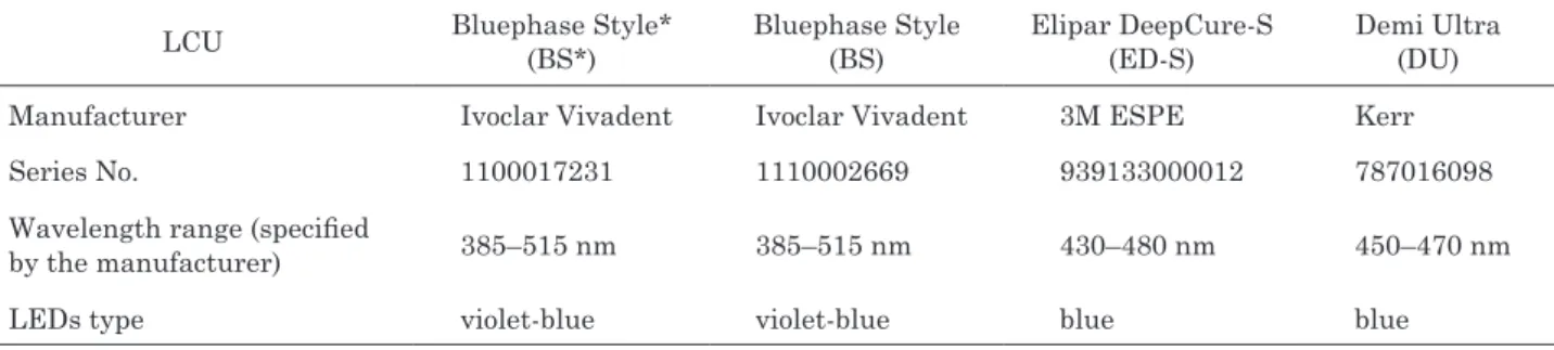
Table 1 Characteristics of the analyzed light-curing units
LCU Bluephase Style*(BS*) Bluephase Style(BS) Elipar DeepCure-S(ED-S) Demi Ultra(DU) Manufacturer Ivoclar Vivadent Ivoclar Vivadent 3M ESPE Kerr Series No. 1100017231 1110002669 939133000012 787016098 Wavelength range (specified
by the manufacturer) 385–515 nm 385–515 nm 430–480 nm 450–470 nm
LEDs type violet-blue violet-blue blue blue
Fig. 1 Different positions of the light-curing unit (here: Bluephase Style) for measuring radiant exposure; view from the detector (D) of the spectrophotometer system - grey); light tip - yellow, LEDs - blue and violet in the a) centered LCU position, b) right LCU position, c) left LCU position, d) upper LCU position, e) lower LCU position.
assessing product reliability.
Characterization of the LCUs
The variation in irradiance and spectral distribution of the blue and violet LEDs according to exposure distance and LCU position was assessed by means of a laboratory-grade, NIST-referenced (National Institute of Standards and Technology) spectrophotometer (USB4000 Spectrometer –MARC [Managing Accurate Resin Curing] System; Bluelight Analytics Inc, Halifax, Canada). The system equipped with a 3648-element array detector (Toshiba linear CCD detector, Toshiba Electronic Devices & Storage, Tokyo, Japan) and high-speed electronics has been spectroradiometrically calibrated with a NIST-traceable light source (Ocean Optics’, Dunedin, FL, USA) with the wavelength between 300 and 1,050 nm. The light detector used was a CC3-UV Cosine Corrector with the diameter of 4 mm. Its dimension is smaller than the size of the light tip and corresponds to a potential restorative size, if RBC samples would be produced. The sensor collects electromagnetic radiation over a 180° field of view in order to soften the optical interference side effect. Irradiance was measured over 10 s at a rate of 16 records/s for five times (n=5) for each curing condition described hereunder: the LCU was stabilized by means of a mechanical arm (for enhanced reproducibility) by considering five different positions as it is shown in Fig. 1: one centered and four decentered positions with a 3-mm offset each to the left, right, lower and upper direction; the LCU was first set directly on the sensor’s surface at 0 mm from the detector, and then moved in one-mm steps away from it, up to an exposure distance of 10 mm. The protocol resulted in
1,100 outcomes (4 LCUs×5 LCU positions×11 exposure distances×5 measurements).
Statistical analyzes
The normal distribution of the data was certified by a Shapiro-Wilk test. Homogeneity of variances was asserted using Levene’s Test which showed that equal variances could be assumed. One-way analysis of variance (general linear model) served to assess the impact of the parameters LCU type, LCU position and exposure distance, as well as the effect of their interaction term on the incident irradiance. The partial eta-squared statistic reported the practical significance of each term, based on the ratio of the variation attributed to the effect. Larger values of partial eta-squared (ηP²) indicate a greater amount of variation that was accounted for by the model, which added up to a maximum of 1.0. As RE is equivalent to the irradiance of a surface integrated over the time of irradiation, the statistical analysis was made considering the data for the RE acquired from the violet and the blue LEDs separately. The statistical analyzes were made using the software SPSS (version 24.0, Chicago, IL, USA), p-values <0.05 indicating statistical significance (95%-confidence interval).
RESULTS
Characterization of the LCUs
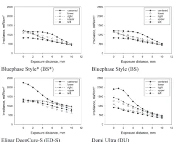
The variation in irradiance reaching the sensor of the spectrophotometer with respect to the position and the exposure distance of the different LCUs is illustrated in Fig. 2. For all LCUs, a considerable decrease in irradiance was observed when increasing exposure distance from 0 mm to 10 mm. Differences between the irradiance values in the centered and decentered LCU positions were found as well. When comparing BS* and BS, differences in irradiance up to ~50 mW/cm2 were found for some of the simulated curing conditions. Figure 3 shows the absolute irradiance integrated over the wavelength (mW/cm2/nm) and illustrates the emission peaks of the analyzed LCUs: BS* and BS have two distinct peaks at 410 nm (violet) and 456 nm (blue), whereas the peak maximum of the blue LCUs is located at 449 nm (ED-S) and 460 nm (DU). Figure 4 highlights the different irradiance pattern of the blue LCUs.
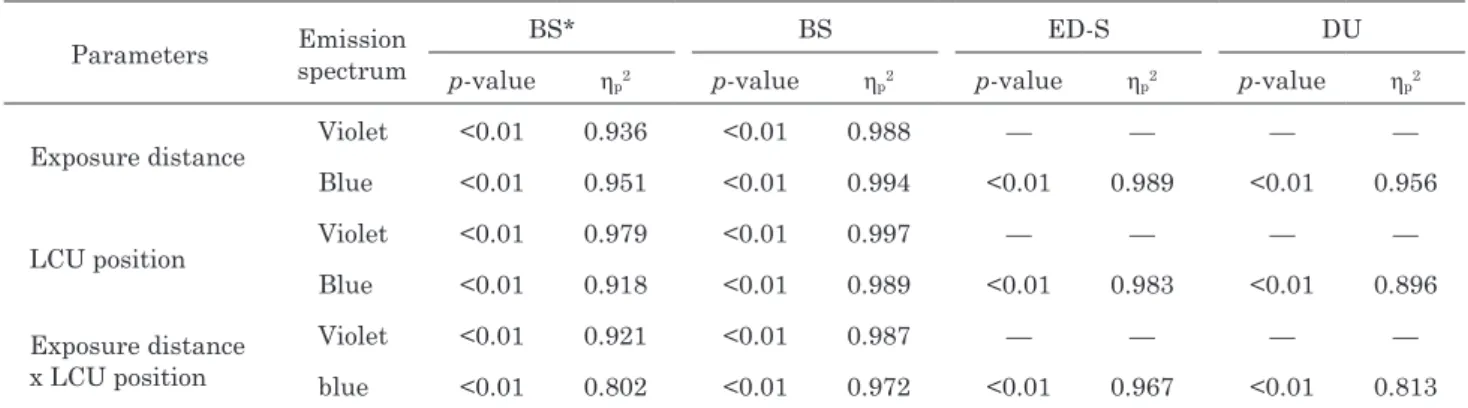
Exposure distance and LCU position as well as their binary combination influenced significantly the RE
Fig. 2 Variation in irradiance (mean values and standard deviation, n=5) delivered at distances up to 10 mm for Bluephase Style*, Bluephase Style, Elipar DeepCure-S and Demi Ultra; different LCU positions in the legend.
Fig. 3 Absolute irradiance integrated over the wavelength of the different analyzed light-curing units in the centered position at 0 mm–violet, 2 mm–yellow, 4 mm–black, 6 mm–green, 8 mm–blue, 10 mm–red. Fig. 4 Irradiance pattern of the analyzed blue
light-curing units: left for Elipar DeepCure-S and right for Demi Ultra.
(p<0.01, Table 2). For BS* and BS, the highest influence on the RE in the violet wavelength region was exerted by the LCU position, followed by exposure distance and their binary combination. For the blue wavelength region of BS* and BS and for the blue LED-LCUs, the highest effect on the RE was exerted by exposure distance, followed by LCU position and their binary combination. The emission spectra of the blue LED-LCUs begins at a wavelength of 410 nm (ED-S) or 420 nm (DU), thus coinciding with the border of the violet wavelength range. Since RE values lower than 1 J/cm2 were identified in the violet wavelength range, this data was not evaluated separately and included in the total RE of the blue LEDs. Tables 3 a, b, c and d present the results for the RE in the violet and in the blue wavelength range for the four analyzed LCUs.
DISCUSSION
The focus of this study was on the analysis of the different
behavior of modern LED-LCUs, and the quantification of possible polymerization deficits due to improper, but clinically relevant curing conditions. A previous study reported that the improper positioning of the LCU can contribute to premature failure of RBC restorations21). The four investigated LCUs deliver distinctive light output features. ED-S is described as an LCU with a homogenous light beam profile, delivering irradiance between 1,000 and 2,000 mW/cm2 across 78.6% of its LCU tip2). It was therefore considered as a reference in
Table 2 Effect of the parameters exposure distance and LCU position on the radiant exposure determined via multivariate analysis (general linear model).
Parameters Emission spectrum BS* BS ED-S DU
p-value ηp2 p-value ηp2 p-value ηp2 p-value ηp2
Exposure distance Violet <0.01 0.936 <0.01 0.988 — — — — Blue <0.01 0.951 <0.01 0.994 <0.01 0.989 <0.01 0.956 LCU position Violet <0.01 0.979 <0.01 0.997 — — — —
Blue <0.01 0.918 <0.01 0.989 <0.01 0.983 <0.01 0.896 Exposure distance
x LCU position
Violet <0.01 0.921 <0.01 0.987 — — — — blue <0.01 0.802 <0.01 0.972 <0.01 0.967 <0.01 0.813 The partial eta-squared statistic reports the practical significance of each term as well as their interaction terms, based on the ratio of the variation attributed to the effect. Larger values of partial eta-squared (ηP²) indicate a greater amount of variation
accounted for by the model.
Table 3 Radiant exposure (RE) identified in the violet and in the blue emission spectrum of the light-curing units: a) Bluephase Style*; b) Bluephase Style; c) Elipar DeepCure-S, and d) Demi Ultra
a) Exp. Dist. (mm) Emission Spectrum RE (J/cm2)
centered right left lower upper
0 Violet 1.90 (0.09) c H 0.52 (0.10)aA 3.48 (0.08)eK 2.29 (0.18)dG 1.01 (0.15)bB Blue 10.47 (0.18)cG 12.53 (0.43)dH 5.19 (0.66)aC,D 9.19 (0.39)bG 11.23 (0.18)cK 1 Violet 1.84 (0.08) c G,H 0.50 (0.10)aA 3.33 (0.07)eJ, K 2.21 (0.17)dG 0.74 (0.09)bA Blue 10.36 (0.19)b,cG 11.84 (0.63)dG,H 5.42 (0.64)aD 9.41 (0.44)bG 10.86 (0.25)c,dJ,K 2 Violet 1.79 (0.06) c F,G,H 0.46 (0.07)aA 3.14 (0.12)dJ 1.99 (0.16)cF,G 0.69 (0.10)bA Blue 10.37 (0.23)cG 10.65 (0.74)cF,G 5.33 (0.61)aC,D 8.77 (0.54)bG 10.41 (0.34)cH,J 3 Violet 1.74 (0.08) d E,F,G 0.46 (0.08)aA 2.87 (0.15)cH 1.75 (0.18)bE,F 0.67 (0.09)aA Blue 10.37 (0.20)cG 9.48 (0.83)cE,F 5.22 (0.62)aC,D 7.81 (0.55)bF 9.89 (0.36)cG,H 4 Violet 1.67 (0.06) b E,F 0.45 (0.07)aA 2.60 (0.14)cG 1.50 (0.16)bD,E 0.67 (0.09)aA Blue 10.29 (0.17)dG 8.32 (0.95)cD,E 5.06 (0.56)aB,C,D 6.91 (0.46)bE 9.24 (0.36)c,dG 5 Violet 1.60 (0.09) d D,E 0.46 (0.07)aA 2.33 (0.11)eF 1.29 (0.12)cC,D 0.66 (0.07)bA
Blue 9.85 (0.11)eF 7.31 (0.83)cC,D 4.87 (0.51)aA,B,C,D 6.13 (0.32)bD,E 8.53 (0.36)dF
6 Violet 1.47 (0.06) d D 0.48 (0.06)aA 1.99 (0.10)eE 1.13 (0.10)cB,C 0.68 (0.06)bA Blue 9.03 (0.13)dE 6.55 (0.75)bB,C 4.65 (0.46)aA,B,C,D 5.53 (0.19)aC,D 7.69 (0.32)cE 7 Violet 1.30 (0.06) dC 0.48 (0.07)aA 1.69 (0.07)eD 1.03 (0.10)cA,B,C 0.67 (0.06)bA Blue 7.92 (0.15)d D 5.86 (0.56)bA,B,C 4.45 (0.39)aA,B,C,D 5.10 (0.14)aB,C 6.84 (0.29)cD 8 Violet 1.12 (0.05) dB 0.49 (0.06)aA 1.41 (0.07)eC 0.93 (0.06)cA,B 0.68 (0.05)bA Blue 6.53 (0.19)d
C 5.32 (0.42)bA,B 4.22 (0.32)aA,B,C 4.71 (0.09)bA,B,C 5.94 (0.26)cC
9 Violet 0.96 (0.03)
dA,B 0.48 (0.05)aA 1.17 (0.05)eB 0.86 (0.05)cA,B 0.66 (0.04)bA
Blue 5.41 (0.19)d
B 4.80 (0.32)b,cA 3.98 (0.26)aA,B 4.35 (0.07)a,bA,B 5.09 (0.17)c,dB
10 Violet 0.83 (0.03)
cA 0.48 (0.05)aA 0.93 (0.05)dA 0.80 (0.05)cA 0.65 (0.05)bA
Blue 4.33 (0.14)b,c
b)
Exp. Dist.
(mm) SpectrumEmission
RE (J/cm2)
centered right left lower upper
0 Violet 2.03 (0.04) cH 0.50 (0.03)aE 3.71 (0.02)dL 2.02 (0.10)cH 0.96 (0.06)bC Blue 10.86 (0.08)b,c H,J 12.17 (0.12)dK 5.08 (0.03)aG,H 10.54 (0.23)bK 11.03 (0.24)cK 1 Violet 1.83 (0.04) cG 0.42 (0.03)aA,B,C 3.54 (0.04)eK 1.94 (0.05)dH 0.79 (0.04)bB Blue 10.94 (0.07)c J 11.03 (0.19)cJ 5.18 (0.08)aH 10.70 (0.14)cK 10.10 (0.29)bJ 2 Violet 1.82 (0.04) cG 0.41 (0.01)aA,B 3.38 (0.05)dJ 1.76 (0.04)cG 0.78 (0.04)bB Blue 10.85 (0.05)d H,J 10.00 (0.23)b,cH 5.14 (0.06)aG,H 10.12 (0.17)cJ 9.70 (0.29)bH,J 3 Violet 1.79 (0.05) dG 0.39 (0.03)aA 3.17 (0.06)eH 1.51 (0.06)cF 0.76 (0.05)bA,B Blue 10.71 (0.08)d H 8.55 (0.18)bG 5.08 (0.06)aG,H 9.06 (0.17)cH 9.15 (0.31)cG,H 4 Violet 1.76 (0.06) dG 0.41 (0.03)aA,B 2.94 (0.07)eG 1.30 (0.03)cE 0.76 (0.04)bB Blue 10.50 (0.06)e G 7.42 (0.18)bF 5.02 (0.06)aF,G 8.05 (0.15)cG 8.64 (0.28)dF,G 5 Violet 1.65 (0.03) dF 0.42 (0.02)aA,B 2.61 (0.03)eF 1.14 (0.04)cD 0.76 (0.04)bA,B Blue 10.06 (0.09)e F 6.58 (0.15)bE 4.90 (0.05)aF 7.11 (0.19)cF 8.09 (0.29)dF 6 Violet 1.52 (0.02) dE 0.44 (0.02)aA,B,C,D 2.27 (0.02)eE 1.01 (0.04)cC 0.76 (0.03)bB Blue 9.14 (0.10)e E 5.97 (0.13)bD 4.72 (0.06)aE 6.30 (0.15)cE 7.44 (0.23)dE 7 Violet 1.35 (0.04) dD 0.46 (0.02)aB,C,D,E 1.87 (0.02)eD 0.89 (0.04)cB 0.76 (0.03)bA,B Blue 8.00 (0.10)d D 5.49 (0.10)bC 4.47 (0.04)aD 5.61 (0.09)bD 6.64 (0.18)cD 8 Violet 1.16 (0.03)
cC 0.49 (0.02)aD,E 1.53 (0.06)dC 0.81 (0.03)bA,B 0.74 (0.03)bA,B
Blue 6.74 (0.04)d C 5.12 (0.08)bB 4.23 (0.07)aC 5.02 (0.07)bC 5.78 (0.19)cC 9 Violet 1.02 (0.01) dB 0.48 (0.02)aD,E 1.24 (0.01)eB 0.76 (0.01)cA 0.72 (0.01)bA,B Blue 5.62 (0.07)e B 4.72 (0.09)cA 3.96 (0.03)aB 4.54 (0.06)bB 4.93 (0.09)dB 10 Violet 0.87 (0.03) cA 0.47 (0.01)aC,D,E 1.01 (0.03)dA 0.71 (0.03)bA 0.67 (0.01)bA Blue 4.66 (0.07)c A 4.31 (0.05)cA 3.70 (0.04)aA 4.04 (0.04)bA 4.17 (0.10)bA c) Exp. Dist. (mm) SpectrumEmission RE (J/cm2)
centered right left lower upper
0 Violet 0.23 (0.01) bF 0.14 (0.02)aB 0.12 (0.01)aC,D,E 0.14 (0.02)aG 0.13 (0.02)aA,B Blue 22.37 (0.05)d K 13.39 (0.42)cH 12.54 (0.07)bJ 13.47 (0.45)cJ 11.89 (0.23)aD,E 1 Violet 0.22 (0.02) bF 0.14 (0.00)aB 0.13 (0.01)aD,E 0.13 (0.01)aF,G 0.11 (0.01)aA,B Blue 21.44 (0.29)c J 12.89 (0.35)bG,H 12.77 (0.19)bJ 12.88 (0.38)bJ 12.03 (0.18)aD,E,F 2 Violet 0.20 (0.01)
bE,F 0.14 (0.02)aB 0.14 (0.01)aE 0.11 (0.01)aD,E,F,G 0.12 (0.02)aA,B
Blue 19.85 (0.35)c
H 12.82 (0.31)bG,H 12.45 (0.15)a,bJ 12.12 (0.37)aH 12.44 (0.20)a,bF,G,H
3 Violet 0.18 (0.01)
bD,E 0.12 (0.01)aA,B 0.13 (0.02)aE 0.12 (0.01)aE,F,G 0.13 (0.01)aB
Blue 17.75 (0.49)d
G 12.75 (0.26)cG 11.96 (0.16)bH 11.26 (0.37)aG 12.70 (0.21)cH
4 Violet 0.15 (0.01)
bC,D 0.14 (0.01)a,bB 0.12 (0.02)aB,C,D,E 0.11 (0.01)aC,D,E,F 0.13 (0.01)a,bA,B
Blue 15.63 (0.35)d
5 Violet 0.13 (0.02)
bB,C 0.13 (0.01)bB 0.11 (0.01)a,bA,B,C,D,E 0.10 (0.02)aB,C,D,E,F 0.12 (0.01)a,bA,B
Blue 13.71 (0.25)d
E 12.12 (0.15)cF 10.68 (0.16)bF 9.53 (0.31)aE 12.25 (0.14)cE,F,G
6 Violet 0.13 (0.00)
bB,C 0.12 (0.01)bA,B 0.12 (0.01)bB,C,D,E 0.08 (0.01)aA,B,C,D 0.12 (0.02)bA,B
Blue 12.39 (0.19)dD 11.48 (0.17)cE 9.96 (0.16)bE 8.72 (0.25)aD 11.67 (0.19)cD
7 Violet 0.11 (0.01)
a,b
A,B 0.12 (0.00)bA,B 0.10 (0.01)a,bA,B,C,D 0.09 (0.01)aA,B,C,D,E 0.11 (0.01)a,bA,B
Blue 11.43 (0.13)dC 10.65 (0.19)cD 9.21 (0.19)bD 7.96 (0.26)aC,D 11.05 (0.16)c,dC
8 Violet 0.11 (0.02)
bA,B 0.09 (0.01)a,bA 0.09 (0.01)a,bA,B,C 0.08 (0.01)aA,B,C 0.11 (0.01)bA,B
Blue 10.71 (0.09)d
B 9.82 (0.19)cC 8.61 (0.13)bC 7.24 (0.25)aB,C 10.40 (0.17)dB
9 Violet 0.10 (0.01)
bA,B 0.09 (0.02)a,bA 0.08 (0.01)a,bA 0.07 (0.01)aA,B 0.09 (0.01)a,bA
Blue 10.17 (0.10)e
A,B 9.03 (0.12)cB 7.94 (0.11)bB 6.58 (0.20)aA,B 9.79 (0.13)dA
10 Violet 0.09 (0.01)
a,b
A 0.09 (0.02)a,bA 0.09 (0.02)a,bA,B 0.06 (0.01)aA 0.10 (0.01)bA,B
Blue 9.61 (0.14)dA 8.18 (0.20)cA 7.24 (0.12)bA 5.98 (0.13)aA 9.37 (0.13)dA d) Exp. Dist. (mm) Emission Spectrum RE (J/cm2)
centered right left lower upper
0 Violet 0.07 (0.01) a C,D 0.06 (0.01)aB 0.05 (0.01)aB 0.06 (0.01)aB 0.06 (0.02)aB Blue 17.07 (0.22)eJ 13.01 (0.42)dG 8.17 (0.40)aJ 11.39 (0.38)cJ 9.66 (0.89)bH 1 Violet 0.06 (0.01) a
B,C,D 0.05 (0.02)aA,B 0.05 (0.01)aB 0.05 (0.01)aA,B 0.04 (0.02)aA,B
Blue 17.40 (0.17)b
J 10.75 (3.22)aF,G 7.74 (0.54)aH,J 10.92 (0.37)aJ 7.93 (0.85)aG
2 Violet 0.08 (0.02)
bD 0.05 (0.01)a,bA,B 0.04 (0.02)aA,B 0.05 (0.01)a,bA,B 0.03 (0.01)aA,B
Blue 16.40 (0.31)c
H 10.92 (0.67)bF,G 6.87 (0.55)aG,H 9.73 (0.33)bH 7.29 (0.82)aF,G
3 Violet 0.07 (0.01)
b
B,C,D 0.04 (0.02)a,bA,B 0.02 (0.02)aA,B 0.04 (0.01)a,bA,B 0.03 (0.01)aA,B
Blue 13.87 (0.41)cG 9.77 (0.47)bE,F 6.27 (0.49)aF,G 8.84 (0.29)bG 6.82 (0.71)aE,F,G
4 Violet 0.06 (0.01)
b
B,C,D 0.04 (0.02)a,bA,B 0.03 (0.01)aA,B 0.04 (0.01)a,bA,B 0.05 (0.01)a,bA,B
Blue 11.10 (0.43)c
F 8.73 (0.40)bD,E,F 5.77 (0.42)aE,F 7.96 (0.26)bF 6.44 (0.61)aE,F
5 Violet 0.05 (0.01)
aA,B,C 0.03 (0.01)aA,B 0.03 (0.01)aA,B 0.04 (0.01)aA,B 0.03 (0.02)aA,B
Blue 9.12 (0.37)c
E 7.69 (0.34)bC,D,E 5.29 (0.39)aD,E 7.13 (0.22)bE 5.97 (0.45)aD,E,F
6 Violet 0.04 (0.01)
a
A,B 0.05 (0.01)aA,B 0.04 (0.02)aA,B 0.03 (0.03)aA,B 0.02 (0.02)aA
Blue 7.48 (0.28)dD 6.73 (0.27)cB,C,D 4.79 (0.36)aC,D 6.39 (0.19)cD 5.49 (0.27)bC,D,E
7 Violet 0.05 (0.01)
a
A,B,C 0.05 (0.02)aA,B 0.03 (0.00)aA,B 0.03 (0.01)aA,B 0.03 (0.02)aA
Blue 6.31 (0.17)d
C 5.87 (0.24)c,dA,B,C 4.29 (0.32)aB,C 5.65 (0.14)cC 4.87 (0.19)bB,C,D
8 Violet 0.03 (0.01)
aA 0.03 (0.00)aA 0.03 (0.01)aA,B 0.03 (0.02)aA,B 0.03 (0.01)aA,B
Blue 5.51 (0.14)d
B 5.08 (0.16)cA,B 3.83 (0.27)aA,B 5.01 (0.14)cB,C 4.32 (0.18)bA,B,C
9 Violet 0.03 (0.01)
a,b
A 0.03 (0.01)a,bA,B 0.01 (0.01)aA 0.04 (0.00)bA,B 0.03 (0.01)a,bA,B
Blue 4.84 (0.11)cA 4.41 (0.12)b,cA,B 3.46 (0.23)aA,B 4.65 (0.50)cA,B 3.86 (0.14)a,bA,B
10 Violet 0.03 (0.01)
a
A 0.02 (0.01)aA 0.03 (0.02)aA,B 0.02 (0.01)aA 0.03 (0.01)aA,B
Blue 4.27 (0.09)c
A 3.88 (0.11)bA 3.15 (0.18)aA 3.97 (0.10)bA 3.43 (0.17)aA
Statistical differences between RE values are described with superscript letters concerning different LCU positions and with subscript letters concerning different exposure distances. The same letters within a row or a column indicate no significant difference in the values (Tukey post-hoc tests); Exp. Dist.=Exposure distance.
the present study. This LCU has a single spectral peak at 449 nm in the blue wavelength region that is located at a lower wavelength than the peaks identified in the other LCUs (456 mm for BS* and BS 2 and 460 nm for DU) (Fig. 3). The other blue LCU, DU, has the LED positioned near the tip of the light guide to avoid energy losses that can be caused by a bent light guide and at the same time to weaken light collimation. In contrast to the other LCUs analyzed, DU showed a particular irradiance pattern (Fig. 4) which varied between a base level of moderate irradiance (1,300 mW/cm2) for 0.75 s and a level with high irradiance (1,550 mW/cm2) for the following 0.25 s. As indicated by the manufacturer, changing the irradiance every second of the polymerization cycle does not allow heat to accumulate. Although ED-S and DU only have blue LEDs, a small part of their light also intersects the violet range at the beginning of their emission spectrum, but have only one spectral peak in the blue wavelength range22). These LCUs provide light in narrow wavelength ranges (ED-S: 410–500 nm; DU: 420–515 nm), compared to BS* and BS described as broad-spectrum LED-LCUs (390–515 nm) which have two distinct emission peaks at 410 nm (violet wavelength range) and 456 nm (blue wavelength range)22). The latter incorporate one violet and two blue LEDs, and their wide emission spectrum finds its importance in the polymerization of dental RBCs with additional photoinitiators, as it perfectly matches the absorption spectra of camphorquinone (CQ) and also the absorption spectra of germanium-based photoinitiators (Ivocerin [bis-(4-methoxybenzoyl)diethyl-germane] and Lucerin TPO, an acyl phosphine oxide)22). Although the absorption spectrum of germanium-based photoinitiators peaks at 408 nm in the violet wavelength region23), it extends up to the blue wavelength range (455 nm), thus interfering with the spectrum of blue LCUs to a high degree. It was reported, that 440 nm is the wavelength at which almost 50% of their peak absorbance occurred23). Since this wavelength is already in the blue emission spectrum, additional photoinitiators can also react to the light of the blue LCUs. Likewise, it was reported that the blue light has the main contribution to RE in deeper layers because of the attenuation of violet light in superficial layers24). However, it is recommended to use broad-spectrum LCUs for the polymerization of RBCs with additional photo-initiators in order to cover their whole absorption spectra25).
Under ideal curing conditions, when the LCUs are placed centered to the sensor of the spectrophotometer, the analyzed violet-blue LCUs delivered lower irradiances compared to the blue LCUs (Fig. 2). For the centered applied blue LCUs, irradiances >1,500 mW/cm2 were identified for an exposure distance of up to 4 mm (ED-S) and up to 3 mm (DU). For DU, a higher irradiance was identified at an exposure distance of 1 mm than in an exposure distance of 0 mm in the centered position.
In vitro studies indicate that curing with an LCU with an irradiance ~1,000 mW/cm2 for ~20 s, thus using a RE of 20 J/cm², might be sufficient for proper polymerization results26,27). Based on this reference, the present study enables the estimation of possible deviations from ideal
curing conditions for clinically relevant situations. Figure 2 illustrates the circumstances under which irradiances >1,000 mW/cm2 were recorded for the analyzed LCUs. With the violet-blue LCUs, it is noticeable that a 3-mm offset to the left already reduces the irradiance registered at 0 mm below 1,000 mW/ cm2,which corresponds to about 70% of the irradiance measured in the centered position at the same distance. When the LCU is shifted to the left, the sensor receives mostly violet light and a very small portion of blue light because of the LED repartition (Fig. 1). Since the attenuation of light depends on the wavelength, light at shorter wavelengths (violet) weakens faster and at smaller exposure distances than light at larger wavelengths (blue) 28). In order to achieve the desired irradiance above 1,000 mW/cm2, ED-S tolerated more easily variations from ideal curing conditions and can also be used clinically decentered in all directions if the exposure distance is not greater than 4 mm. This fact is of great significance for curing bulk-fill RBCs, so that sufficient irradiance also reaches the bottom of the restoration if the material is placed in bulk (4 mm)29).
The LCUs in this study were clamped perpendicularly to the sensor’s surface. The inclination of the LCU or a special clinical situation in the oral cavity would not allow this “best-case” scenario30). For example, if the LCU is inclined by 45°, the energy received by the RBC is reduced by 56%31). Taking into account the fact that the ideal direct contact of the light guide tip to the restoration is not always possible due to clinical issues, the reference exposure distance selected in this study was 3 mm. As a result, ED-S performed the best and can ensure reliable polymerization even when used in a decentered manner. DU requires attention when shifted in upper position, as its performance in this position is only sufficient if curing occurs at an exposure distance of 0 mm. DU, as well as the violet-blue LCUs BS* and BS cannot guarantee sufficient polymerization if they are shifted to the left. The violet-blue LCUs should be centered or used in the lower position at most, since exposure distances of less than 3 mm are required for the right and upper LCU positions. In order to supply a RBC restoration with the same RE and thus achieve similar degrees of conversion, an LCU that is characterized by a low irradiance would require more light exposures than an LCU with high irradiance. A reduced irradiance could be compensated by a longer exposure time than recommended by the manufacturer3). On the other hand extending the exposure time can be risky, as heat build-up above 5.5°C can irreversibly damage the pulp and surrounding soft tissues32).As the averaged irradiance and the RE recorded from all analyzed LCUs were significantly affected by LCU position and exposure distances, both null hypothesis were rejected.
In view of the clinical impact of the results of this study on all LCUs analyzed, it is strongly recommended that the light-curing tip be centered over the restoration and that the distance between the light-curing tip and the restoration be less than 3 or 4 mm in order to achieve sufficient polymerization. Since the analyzed blue-LED
LCUs ED-S and DU performed better than the violet-blue-LED LCUs when shifted in different directions, clinicians should be more careful with the position of the light tip in relation to the restoration when using an LCU with two different emission peaks (such as BS and BS *)
With more information about the LCU being used, dentists have a better chance of optimizing the exposure protocol for their LCU/RBC combination and determining the ideal irradiance/exposure time sequence. It is important for dentists and researchers to know the limits of varying the LCU position and the exposure distance in order to achieve the necessary irradiance for a satisfactory polymerization. ED-S with a more homogeneous light beam profile tolerates deviations from the ideal curing conditions more easily than the other analyzed LCUs (BS *, BS and DU) and could ensure a more reliable polymerization.
CONCLUSIONS
LED LCUs with a more homogeneous light beam profile achieve acceptable irradiance levels in all positions up to an exposure distance of 4 mm, while the tolerable exposure distance is much lower for the other LED-LCUs analyzed. It is important for dentists to know how the LCUs used behave and what deviations from the ideal polymerization conditions can be tolerated in clinically relevant situations when the position of the LCU and the exposure distance change.
REFERENCES
1) Price RB, Ferracane JL, Shortall AC. Light-curing units: A review of what we need to know. J Dent Res 2015; 94: 1179-1186.
2) Shimokawa CA, Turbino ML, Harlow JE, Price HL, Price RB. Light output from six battery operated dental curing lights. Mater Sci Eng C Mater Biol Appl 2016; 69: 1036-1042. 3) Price RB, Labrie D, Rueggeberg FA, Sullivan B, Kostylev I,
Fahey J. Correlation between the beam profile from a curing light and the microhardness of four resins. Dent Mater 2014; 30: 1345-1357.
4) de Magalhaes Filho TR, Weig Kde M, Werneck MM, da Costa Neto CA, da Costa MF. Odontological light-emitting diode light-curing unit beam quality. J Biomed Opt 2015; 20: 55005.
5) Ferracane JL, Mitchem JC, Condon JR, Todd R. Wear and marginal breakdown of composites with various degrees of cure. J Dent Res 1997; 76: 1508-1516.
6) Leprince JG, Hadis M, Shortall AC, Ferracane JL, Devaux J, Leloup G, et al. Photoinitiator type and applicability of exposure reciprocity law in filled and unfilled photoactive resins. Dent Mater 2011; 27: 157-164.
7) Ilie N, Obermaier J, Durner J. Effect of modulated irradiation time on the degree of conversion and the amount of elutable substances from nano-hybrid resin-based composites. Clin Oral Investig 2014; 18: 97-106.
8) Casselli DS, Faria-e-Silva AL, Casselli H, Martins LRM. Effect of curing unit and adhesive system on marginal adaptation of composite restorations. Gen Dent 2012; 60: e408-412. 9) Rasines Alcaraz MG, Veitz-Keenan A, Sahrmann P, Schmidlin
PR. Direct composite resin fillings versus amalgam fillings for permanent or adult posterior teeth. Cochrane Database Syst
Rev 2014; 3: Cd005620.
10) Mouhat M., Mercer J, Stangvaltaite L, Örtengren U. Light-curing units used in dentistry: factors associated with heat development-potential risk for patients. Clin Oral Investig 2017; 21: 1687-1696.
11) Shortall A, El-Mahy W, Stewardson D, Addison O, Palin W. Initial fracture resistance and curing temperature rise of ten contemporary resin-based composites with increasing radiant exposure. J Dent 2013; 41: 455-463.
12) Mutluay MM, Rueggeberg FA, Price RB. Effect of using proper light-curing techniques on energy delivered to a Class 1 restoration. Quintessence Int 2014; 45: 549-556.
13) Price RB, Strassler HE, Price HL, Seth S. The effectiveness of using a patient simulator to teach light-curing skills. J Am Dent Assoc 2014; 145: 32-43.
14) Rueggeberg FA. State-of-the-art: dental photocuring —a review. Dent Mater 2011; 27: 39-52.
15) Shimokawa CA, Harlow JE, Turbino ML, Price RB. Ability of four dental radiometers to measure the light output from nine curing lights. J Dent 2016; 54: 48-55.
16) Kirkpatrick SJ. A primer on radiometry. Dent Mater 2005; 21: 21-26.
17) Price RB, Labrie D, Rueggeberg FA, Felix CM. Irradiance differences in the violet (405 nm) and blue (460 nm) spectral ranges among dental light-curing units. J Esthet Restor Dent 2010; 22: 363-377.
18) Michaud PL, Price RB, Labrie D, Rueggeberg FA, Sullivan B. Localised irradiance distribution found in dental light curing units. J Dent 2014; 42: 129-139.
19) Shortall AC, Felix CJ, Watts DC. Robust spectrometer-based methods for characterizing radiant exitance of dental LED light curing units. Dent Mater 2015; 31: 339-350.
20) Price RB, Felix CA. Effect of delivering light in specific narrow bandwidths from 394 to 515nm on the micro-hardness of resin composites. Dent Mater 2009; 25: 899-908.
21) Overton JD, Sullivan DJ. Early failure of Class II resin composite versus Class II amalgam restorations placed by dental students. J Dent Educ 2012; 76: 338-40.
22) Ilie N, Luca BI. Efficacy of modern light curing units in polymerizing peripheral zones in simulated large bulk-fill resin-composite fillings. Oper Dent 2018; 43: 416-425. 23) Moszner N, Fischer UK, Ganster B, Liska R, Rheinberger
V. Benzoyl germanium derivatives as novel visible light photoinitiators for dental materials. Dent Mater 2008; 24: 901-907.
24) Watts D. Reaction kinetics and mechanics in photo-polymerized networks. Dent Mater 2005; 21: 27-35.
25) Lima RBW, Troconis CCM, Moreno MBP, Murillo-Gomez F, De Goes MF. Depth of cure of bulk fill resin composites: A systematic review. J Esthet Restor Dent 2018; 30: 492-501. 26) Ilie N, Stark K. Curing behaviour of high-viscosity bulk-fill
composites. J Dent 2014; 42: 977-985.
27) Ilie N, Stark K. Effect of different curing protocols on the mechanical properties of low-viscosity bulk-fill composites. Clin Oral Investig 2015; 19: 271-279.
28) Ilie N. Impact of light transmittance mode on polymerisation kinetics in bulk-fill resin-based composites. J Dent 2017; 63: 51-59.
29) Margeas RC. Bulk-fill materials: simplify restorations, reduce chairtime. Compend Contin Educ Dent 2015; 36: e1-4. 30) Price RB, Shortall AC, Palin WM. Contemporary issues in
light curing. Oper Dent 2014; 39: 4-14.
31) Price RB, McLeod ME, Felix CM. Quantifying light energy delivered to a Class I restoration. J Can Dent Assoc 2010; 76: a23.
32) Runnacles P, Arrais CA, Pochapski MT, Dos Santos FA, Coelho U, Gome JC, et al. In vivo temperature rise in anesthetized human pulp during exposure to a polywave LED light curing unit. Dent Mater 2015; 31: 505-513.