二枚の写真から回転体の三次元形状を復元する方法
6
0
0
全文
(2) imaged revolution axes is exploited and an equation for computing the orientation of the revolution axis is derived. At last the contour generator is determined from the rectified images and the SOR is reconstructed by rotating the contour generator about the revolution axis. Most of the existing techniques for the reconstruction of SOR made use of a single monocular image to infer geometric information from the silhouette [1] [2] [3]. In [1], an algorithm was proposed which makes use of the invariant properties of a SOR to calibrate the camera and rectify the image, surface normal along the contour generator are then determined from the rectified silhouette, a parameterization formula of the contour generator is derived using a coplanarity constraint between the surface normal and the revolution axis and the 3D shape of the SOR is recovered. However, the ambiguity in the orientation of the revolution axis cannot be correctly resolved. These methods only work with normalized camera with zero skew and known aspect ratio. Besides, they require the presence of at least one perspective image of cross section of the object. The method introduced here works with general uncalibrated camera, and it does not need the existing of visible cross sections. Therefore it also can be used for those objects without visible cross sections and a SOR can be recovered up to an unknown scale by this method. In Section 2, we give an introduction of the theoretical background for reconstructing a SOR from a single uncalibrated image. In Section 3, we present a method for reconstructing a SOR from two uncalibrated images. The algorithm and implementation are described in Section 4 and results of real data experiments are presented in Section 5. Finally, conclusions are given in Section 6.. rotating C to this particular position and a latitude circle which is a circle through r with its center on the axis. The meridian curve and latitude circle are orthogonal [4]. The contour generator Γ is the set of points X on S at which rays are tangent to the surface. The corresponding image apparent contour γ is the set of points x which are the image of X , i.e. γ is the image of Γ . The contour generator Γ only depends on the relative position of the camera centre and the SOR. The apparent contour γ is defined by the intersection of the image plane with the rays to the contour generator, and so depends on the position of the image plane. In general, under perspective projection Γ is space curve. Under perspective projection, if the camera is pointing towards the revolution axis of a SOR and if the camera also has unit aspect ratio, the silhouette of the SOR will become bilaterally symmetric. This property of the image of SOR can be used to rectify the images such that the resultant silhouette is bilaterally symmetric. In [1], a harmonic homology defined by the image of the revolution axis and a vanishing point is used to rectify the image [5] [6]. In this paper, we rectify the image by calculating a planar homography from the symmetry property of the image of SOR. 2.2 Parameterization of contour generator Let S r ( s, θ ) = [ X ( s ) cos θ Y ( s ) X ( s ) sin θ ]T be a SOR generated by rotating a meridian curve C r = [ X ( s ) Y ( s ) 0]T about the y–axis and a pinhole camera Pˆ = [ I 3 − c ] centered at c = [0 0 − d z ]T with d z > 0 (Fig. 1). The contour generator Γ (s) can be parameterized as [1]. Γ (s) = c + λ (s) p (s), where p (s) ⋅ n (s) = 0,. 2. Properties of surface of revolution. where p(s) = [ x ( s ) y ( s ) 1] is the viewing vector from c to the focal plane at unit distance for the point Γ (s) , and λ (s) is the depth of Γ (s) from c along the z direction. n(s) is the unit surface normal at Γ (s) which can be determined as the cross T. 2.1 Symmetry property of SOR A surface of revolution S is a surfaceT created by rotating a plane curve C about an axis in the same plane. Through any point r of S there is a meridian curve which is the curve obtained by. (1). − 2−.
(3) product between p(s) and the tangent along silhouette at p(s) [1].. Γ ( s ) = c + λ (s) p (s) z. ⎤ ⎡d z y& ( s ) x( s ) ⎥ ⎢d y& ( s )( y ( s ) cosψ − sinψ ) z ~ ⎥, Γ ψ (s) = ⎢⎢ ⎥ d zα ψΓ~ ( s ) ⎥ ⎢ ⎢⎣ y& ( s )( y ( s ) sinψ + cosψ ) − α ψΓ~ ( s )⎥⎦. (5). where. α ψ (s) = {( x& (s) y(s) − x(s) y& (s)) cosψ − x& (s) sinψ }x(s). ~ Γ. x λ (s ). y p( s ) = [ x(s) y (s) 1]T. c = [0 0 − d z ]T Fig. 1. A surface of revolution, whose axis of revolution coincides with the y–axis, being viewed by a pinhole camera centered at c It can be shown that the surface normal at point Sr (s 0 ,θ 0 ) is normal to the meridian curve through Sr (s 0 ,θ 0 ) and lies on the plane containing the y–axis and point S r (s 0 ,θ 0 ) . This coplanarity constraint can be expressed by [6] [7]. n(s)T [ny ]× Γ ( s ) = 0,. (2). where n y = [0 0 1] . This can be expanded to recover the depth T. λ (s) =. d z n1 ( s ) , n1 ( s ) − n3 ( s ) x( s ). (3). and the contour generator can then be recovered in homogeneous coordinates as. ⎡d z y& ( s ) x( s ) ⎤ ⎢d y& ( s ) y ( s ) ⎥ ~ z ⎥, Γ (s) = ⎢ ⎢d zα Γ~ ( s ) ⎥ ⎢ ⎥ ⎣⎢ y& ( s ) − α Γ~ ( s )⎦⎥. 3. Reconstruction from two images 3.1 Image rectification When a camera is rotated about its center with no change in the internal parameters, and if ~ x and ~ x′ are the images of a point X before and after the rotation, then. ~ x′ ≅ KRK −1 ~ x,. (6). where K is the camera calibration matrix and R is the rotation matrix. From the symmetry properties of SOR and its silhouette discussed in Section 2.1, given K , it is possible to rectify the image of a SOR by a planar homography H induced by a rotation such that the resultant silhouette is bilaterally symmetric about the y–axis. This corresponds to rotate the camera about its optical center until the revolution axis of the SOR lies on the y–z plane at the camera coordinate system. Note that the homography is not unique, since any homography H ′ , given by H ′ = Rx (ψ ) H where Rx (ψ ) is a rotation about the x–axis by an angle ψ , will also yield a silhouette which will be bilaterally symmetric about y–axis. 3.2 Computation of the revolution axis. (4). where α Γ~ ( s ) = ( x& ( s ) y ( s ) − x( s ) y& ( s )) x ( s ) . Such reconstruction is determined up to a similarity transformation since the distance d z cannot be recovered. In general case, if the SOR is rotated about x–axis by an angleψ , the equation (4) of the contour generator becomes. In order to recover the shape of SOR using Eq. (5), the orientation of the revolution axis ψ must be determined first. This can be estimated using perspective images of one or two cross sections of the SOR [1] [8]. But for those that have no visible cross sections, these methods do not work. In this section, we will show that this angle can be calculated using two images of SOR and no cross section is needed. For two images of a SOR from two different. − 3−.
(4) viewpoints, we first compute the motion between the two images and calibrate the two cameras using corresponding points. Let R and t be the rotation matrix and translation vector, respectively. Then. X 2 = RX 1 + t , where X 1 and X 2 are the camera coordinates of a 3D point X in image 1 and 2, respectively. Next we rotate the camera 1 about its optical center to rectify the image 1 such that the resultant silhouette is bilaterally symmetric about the y–axis. We have. X1′ = R1 X1 ,. X 2′ = R2 X 2 ,. ,. (9). where RN = R2 RR , t N = R2 t .. Axis of SOR A. O. Image 1'. θ. (11). where rij denotes the ij element of RN , ti denotes the ith element of t N . Since R, R1 , R2 and t are known, RN and t N can be calculated. Solving Equation (11), we have (12). 4. Algorithm and implementation 4.1 Computation of homography Let H = KRK −1 be the homography matrix where K is the camera calibration matrix and R is the rotation matrix. There are several ways to represent a rotation, here we use Euler angles which are rotational angles around the three Cartesian coordinate axes. R(α , β , γ ) = R( z, α ) R( y, β ) R( z , γ ) .. −1 1. Let m, m′ be the images of a point X before and after the rotation, and m lies on the silhouette ρ of the SOR. Then. d. Image of axis. C2. − r12α cosθ + r13d − r13α sin θ + t1 = 0.. tan θ = − r12 / r13 .. where X 2′ is the coordinate of the point X in camera coordinate system of camera 2 after rotation, R2 is the rotation matrix of camera 2. Then. (10). Since O and A lie in the y–z plane of camera 2, the x coordinates of O and A are equal to zero, we have. (8). R −2 1 X 2′ = RR1−1 X1′ + t .. Image 2'. X A 2 = RN X A1 + t N .. r13d + t1 = 0,. where X 1′ is the coordinate of the point X in camera coordinate system of camera 1 after rotation, R1 is the rotation matrix of camera 1. We also rectify the image 2 by rotating camera 2 and we have. = RN X 1′ + t N. X O 2 = RN X O1 + t N ,. (7). X 2 = RX 1 + t = RR1−1 X1′ + t ,. X 2′ = R2 RR1−1 X 1′ + R2 t. coordinate system of camera 1 (Fig. 2), respectively. Where θ is the orientation of revolution axis of SOR in y–z plane of camera coordinate system, α is a scale factor which represents the distance for O to A along the revolution axis, d is the distance from the center of camera 1 to O. Then the cameras coordinate of O and A under camera coordinate system of camera 2 can be calculated from Eq. (9) as. m′ = Hm . R N ,t N. C1. Fig.2. Motion between two imaged axes of SOR after the rectification of the two images Let O and A be two points lie on the revolution axis of the SOR with 3D coordinates X O1 = [0 0 d]T and X A1 = [0 − α cosθ d − α sinθ ]T under camera. Next we perform a transformation which maps m ′ to a point m ′′ such that m ′ and m ′′ are symmetric about the axis which pass through the center of the image plane and points down, i.e.. m′′ = H1m′ + [ w 0 0]T = H1 Hm + [ w 0 0]T , where w is the width of the image and H1 is the. − 4−.
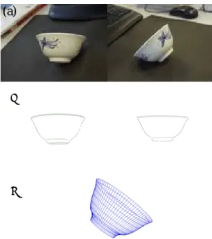
(5) diagonal matrix H1 = diag(-1,1,1) . Let H 2 be a homography which performs a reverse transformation of H and has the form H 2 = KR′K −1 , where. R′ = R −1 = R( z ,−α ) R( y,− β ) R( z ,−γ ) . Let m ′′′ be the image after transformation of m′′ , then. m′′′ = H 2 m′′ = H 2 H1 Hm + H 2 [ w 0 0]T .. orientations of the revolution axis of these examples are shown in Table 1. The ratio of the height and the diameter of the topmost circle of the objects that are measured manually and calculated from the reconstructed model are also shown in Table 1. From Table 1, we see that the ratios of the topmost circle to the height of the objects calculated by the proposed method are close to the truth values.. (a). Since H and H 2 are functions of α , β , γ and H1 , K are known, the rotation matrix R related to the homography H can then be calculated by optimizing the cost function. Cost ( R(α , β , γ ) = ∑ dist (m′′′, ρ ) 2 ,. (b). where dist ( m ′′′, ρ ) is the distance from the transformed point m ′′′ = H 2 H1 Hm + H 2 [ w 0 0]T to the original silhouette ρ . This can be solved by the Levenberg–Marquardt method [9].. (c). 4.2 Depth recovery Since the rectified silhouette is bilaterally symmetric about the y–axis, only one side of it needs to be considered during the reconstruction of the SOR. The apparent contour is first segmented manually from the rectified silhouette. Points are then sampled from the apparent contour and the tangent vector at each sample point is estimated by fitting a polynomial to the neighboring points. Finally, the depth of each sample point is recovered using Eq. (5), and the contour generator and the SOR follow.. Fig.3. (a) Images of a bowl. (b) Rectified silhouettes of the bowl. (c) Reconstructed model.. (a). 5. Experiments and results. (b). Experiments were carried out to demonstrate the effectiveness of our approach. The silhouette of a SOR is extracted from the image by applying a Canny edge detector [10]. The initial motion between the two images is calculated by 3DM–Modeler, software developed by 3DMedia Co., Ltd. Fig. 3 shows the reconstruction of a bowl. The rectification of the silhouette (Fig.3 (b)) was done using the algorithm described in Section 4. Fig. 4 and Fig. 5 show other examples of a vase and a bowl. The. (c). Fig.4. (a) Images of a vase. (b) Rectified silhouettes of the vase. (c) Reconstructed model.. − 5−.
(6) (a) References. (b). (c). Fig.5. (a) Images of a bowl. (b) Rectified silhouettes of the bowl. (c) Reconstructed model. Table 1. Orientation and Ratio.. θ (°). Ratio(height/diameter) Measure. Reconstruction. Bowl 1. -9.83. 0.50. 0.48. Vase. -26.9. 5.00. 5.00. Bowl 2. -25.9. 0.51. 0.52. 6. Conclusions In this paper, a novel approach is proposed to reconstruct a surface of revolution from two uncalibrated views. The motion between two images is calculated using corresponding points, and then the images are rectified such that the resulting images show symmetry about y–axis. A computation of the motion between the two rectified images is performed and the result is used to compute the orientation of revolution axis. The depth of contour generator is then calculated and the SOR is reconstructed up to a scale. The test results demonstrated the effectiveness of the approach.. [1] K.-Y. K. Wong, P. R. S. Mendonça, and R. Cipolla, “Reconstruction of surfaces of revolution from single uncalibrated views,” Proc. British Machine Vision Conference 2002, vol. 1, pp. 93–102, September 2002. [2] Bimbo A. D. Colombo, C. and F. Pernici, “Uncalibrated 3d metric reconstruction and flattened texture acquisition from a single view of a surface of revolution,” 1st International Symposium on 3D Data Processing Visualization and Transmission (3DPVT’02), June 2002. [3] S. Utcke and A. Zisserman, “Projective reconstruction of surfaces of revolution,” in DAGM03, pp. 265–272. [4] R. Cipolla, A. Blake, Surface shape from the deformation of apparent contours, International Journal of Computer Vision 9 (2) (1992) 83–112. [5] P. R. S. Mendonça, K.-Y. K.Wong, and R. Cipolla, “Epipolar geometry from profiles under circular motion,” IEEE Trans. on Pattern Analysis and Machine Intelligence, vol. 23(6), pp. 604–616, June 2001. [6] H. S. M. Coxeter, Introduction to Geometry, Wiley and Sons, New York, January 1989. [7] R. Cipolla and P.J. Giblin. Visual Motion of Curves and Surfaces. Cambridge University Press, 1999. [8] H. Zhang, K.-Y.K. Wong and P.R.S. Mendonça. “Reconstruction of Surface of Revolution from Multiple Uncalibrated Views: A Bundle-Adjustment Approach,” In Proc. Asian Conference on Computer Vision (ACCV2004), pp. 378-383, Jeju Island, Korea, January 2004. [9] W. H. Press, S. A. Teukolsky, W. T. Vetterling, and B. P. Flannery, Numerical Recipes in C : The Art of Scientific Computing, Cambridge University Press, Cambridge, UK, January 1993. [10] J. Canny, “A computational approach to edge detection,” vol. 8(6), pp. 679–698, November 1986.. − 6−E.
(7)
図

関連したドキュメント
In Section 3, we show that the clique- width is unbounded in any superfactorial class of graphs, and in Section 4, we prove that the clique-width is bounded in any hereditary
In this paper, under some conditions, we show that the so- lution of a semidiscrete form of a nonlocal parabolic problem quenches in a finite time and estimate its semidiscrete
Keywords: continuous time random walk, Brownian motion, collision time, skew Young tableaux, tandem queue.. AMS 2000 Subject Classification: Primary:
Then it follows immediately from a suitable version of “Hensel’s Lemma” [cf., e.g., the argument of [4], Lemma 2.1] that S may be obtained, as the notation suggests, as the m A
Applications of msets in Logic Programming languages is found to over- come “computational inefficiency” inherent in otherwise situation, especially in solving a sweep of
Shi, “The essential norm of a composition operator on the Bloch space in polydiscs,” Chinese Journal of Contemporary Mathematics, vol. Chen, “Weighted composition operators from Fp,
[2])) and will not be repeated here. As had been mentioned there, the only feasible way in which the problem of a system of charged particles and, in particular, of ionic solutions
This paper presents an investigation into the mechanics of this specific problem and develops an analytical approach that accounts for the effects of geometrical and material data on
