NII-Electronic Library Service
'
[nt
"1
.
Journal
efStructvral
andCenstructien
Engineering
H4kza\ftasxxXas"WthE
uDc:6i4.s4:6gl.32
,
(TransactionsofAIJ)No.384,,February,
lgss
'
rg
3s4
g・Hea
63
¢2A
'
SIMPLE
FORMULATION
FOR
STRESS-STRAIN
RELATIONOFCONCRETEAT
'
'
・
/'
'
ELEVATED
TEMPERATURE・
t
'
・
byFUKUJIRO
FURUMURA*,
CHANG
HEE
OH**,
'
TAKEO
AVE'*",
and
WHA
JUNG
KIM"",
Members
of'
.
.
A.LJ.
'
t
t
1.
Introduction
'
The
mechanicalpropgrties
ofconcrete
at elevatedtemperature
has
been
neededin
connection
withthe
develbpment
ofprestresSed
concretepressure
vesselsf6r
nuclearpower
blants
and withthe
research onthe
behavior
'
of
reinforcedconcrete
membersunder
fire
condition.
'
'
The
success of analyzingthe
behavior
of concrete structures at elevatedtemperature
gr6atly
depends
onhow
accurately certain mechanicalproperties,
especiallythe
stress-strain curve, creep andthermal
exp'ansion
canbe
determined
inawide
temperature
range..
''
iAnalytical
expressionfor
stress-strain curveis
veryimportant,
because
it
provides
asignificantinformation
ofthe
internal
stress
againstthe
deformtition
ofaconcretestructure.
・'
'
'
'
In
orderto
carry outthe
ultimateflexure
analysis of reinforced concrete members and others,the
experimental' and'
mathematical
expressions
for'the
relationship
between
stress
and
strain
for
coricrete
haVe
been
Performed
b\
many
authorsi)--i.
.
,.
'
ttand
There
have
been
veiyfew
attemptsto
studythe
behavior
of concrete under・cyclicloading
at elevatbd・temperatureto
aimsat
the
Eational
approachto
the
problem
of
incremental
deformations
of
reinfotced
concrete structuressubjected
te
variablestress
・and
temperature
in
fire
hazards.
In
this
paper
the
relationshipbetween
stress and strain ofplain
concreteat
ele'vatedtemperatures
whichis
based
onthe
experimental
results6)is
ptesented.
The
simple
fprmulation
for
stress-strain
relationof
concrete
at
elevatedtemp'erature
is
neededto
asstirethe
safety of' reinforced concrete structures againstheat
resistance andfire
hazards.
o
, 400,
"Q
.-,,g'O]
Q
o'
ft-240---
rxH
'm
re5
'o
.'-'rg-{
fnL-th
-:tiil;ill,lii・tl,ill,l:///ll・11.---
/・-・-pt S:Sptc.1intp C:Arm Stiovlder<Xksit
e;SphtrtealUtllr
D:TicRina'7eo
K:MLve"LlePlute:m
40
-iEll
e
E:PLpeG:LoadCc:1 1:VpperCrosshEoaFig.1
F;FurnsctIS :Lowtr.CrosshtadDetails
efthe
loadlng
1,:FSItdet"te
MiDLtlventLul
'Cruusi":-tr'
N:AuxilLHry Plste assembly and extensomete.
'
* ** *"##
Prof.
ofTokyo
Institute
ofTechnoLogy,
'Dr.
Sci.
Por[
ofHan
Yang
Univ.
(KOREA'),
Dr,
Sci.
in
Assoeiate
Prof.
pf
Tekyo
Institute
ofTech,
Dr.
S
Graduate
Student,
M.
Sci.
in
Eng.,
(Manusc[ipt
TecetvedMurch
25, lg8T)in
Eng.Eng.ci.
in
Eng.
-1-Architectural Institute of Japan
ArchitecturalInstitute of Japan
2,
Test
program
The
tests
measuring
stress-strain
curves
were
carried
out
on
a
universaltesting
machine
<]50
ton)
equipped withan
electric
furnace
of3
partial
heaters.
The
details
ofthe
loading
assembly and extensometeris
shown
in
Fig,
1.
As
ageneral
rttle,temperature
wasincreased
atthe
rate of about10Clminute,
To
obtain an evendistribution
oftemperature
in
aspecimen andget
rid ofthermal
expansion and shrinkage,test
specimens werekept
for
1-1.
5
hours
at eachtest
tempeTature.
The
detail
oftest
procedures
is
described
in
Ref.(6).
And
additional
tests
has
been
performed
to
obtain
thermaL
expansion,
weightlosses
at
varioustemperatures
and stTess-strainloops
during
unJoading and reloading.Test
specimens
were:A1
series ofconcrete
specimens
(Usual
Strength
Cencrete)
:
5
¢
×10
cm
cylinders,age
1
year,
Portlafid
cement,Tama
River
sand andgravel,
1
cm maximum size, cement-sand-gravel ratio1
:
2.8
:
2.9,
water-cement ratio70
%,
slump
15cm,
cornperssive strength238kglcrne,
rnodulusof
etasticity(E,i,)
25.2
×!O`kglcm2,
A2
series
of
concrete
specimens(High
Strength
Concrete)
:
5
eXIO
cm
cylinders, age3-4
months,Portland
cement,
Tama
River
sand anclgravel,
1
cm maximum size, cernent-sand-gravel ratiol
:
1.9
:
2.0,
water-cementratio
45
%,
slump
5.9cm,
compressive strength457kglcm2,
modulus of elasticity(E,/,)
29.5
×10`
kglcm:.
Additional
test
specirnens were:
A3
series of concrete specimens:
age10
years,
Portland
cement,Tama
River
$and andgravel,
1
cm maxirhumsize,
cement-sand-gravel
ratio1:2.8:2.9,
water-cernent ratio65
%,
slump15cm,
compressive strength of235kglcm2,
modulus of elasticity(E,ls>
20.lxlO`kglcm2.
3.
Shape
ot
stress-strain
curve
The
instantaneous
axialdeformation
of a specimen under cyckicloading
canbe
described
convenientlyby
a stress-straln curve.A
generalized
diagram
of
stress-strain relationfor
concrete
undercyclic
loadings
is
shownin
Fig.2,
where a,B
and
7
represent L`envelopecurve", "unloading curve" stn
and
"reloadingcurve",
respectively.
For
analytical
predictions
of
the
behavior
of reinforced concrete structures underloading
at elevatedtemperatures,
three
curves are needed
to
forrn
an
analyticalexpression.
The
empirical
formulae
of usuatstress-strain
curves are mostly expressed withthe
exponentialforms
asthe
functions
of maximum stress, strain at maximum stress anclinitial
tangent
medulus.Therefore,
these
factors
must
be
determined
asthe
function
oftemperature
for
envelope
curves at varioustemperatures,
From
ex-perimental
results shownin
Figs.3
and4,
the
rela--,)
ansentm
oan
g-sut
tco o monotonousleadingtLttt
t-u-t
.tt..ttI..
cyclicloadingr2S=i/ e e.1Fig3-1
e,2 o.s a.a
STR-IN
C
:
l
Experimental
stress-strainO.5o.s
STRAINt1J
Fig.2
GeneTalized
stress-strain curyesfor
concrete. m-ng)
am
i:.1oo
ooo,tO,2
curves of usual strength concrete
(Al)
a,s o.4 o.s
STRAINCX)
at canstant temperature,a,E
-2-NII-Electronic Library Service
tionships
between
eachfactor
andtemperature
are shownin
Figs.5,6
and7.
Accordingly,
the
factors
can
'
expressed as
follows:
'
for
Al
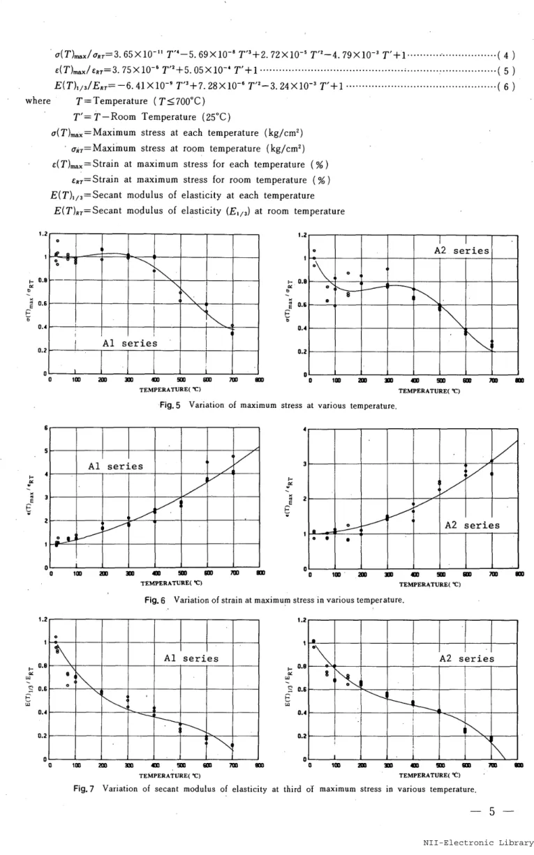
series;a(T)maxloRT==2.
04
×10su"
T"-2,
56
×10-'
T'S+7.
35
×10"`
T"-4.
53
×le-4
T'+1・・・・・t・・・・・・-・・・・・-・・・・・・・・(
1
)
'
E(T)ma.IE,,!3.
99
×10'fi
T't+2,
30
×10-S
T'+1・・・・・・・・・--・・・-・・・・・・・-・・・・・・・・・・・・・・・・・・・・・・・・・・・t・・・.,...(
2)
E(T>v,IE..=::
-6.
79
×10'"
T'S+s.
27
×10L6
T'i-3.
ssxloi3
T'+1
・・・・・・・・・・・・-・・・-・・・-・・・・・・・・・・-・・・・・・・・・・・・-・(
3
)
for
A2
serise;
. su m
}
angethIM
oanlb
amfzavth 1co og-geutIM
oan oo.tO,2O.3o.iaso,s oO.1O.1e.1tr.4e.so.s oo.lo.2o.sO,4o.so.s,x.
zmx$zaico
o{S
aming
o e osuNuhm!mNtsIM
e e.1P,lO.2o,lo.sO.6 e.1O.1o,so.4o.fiO.6 li/!ll.---500
℃ i:' //1//'t-t1I'
-...
:f'!:omoo.t o.!D,ee,io.s o,soJ o,e
be
,)vgeta
m 1co ooo.tFig.
3-2
o.#Experimentat
o,s e.e STRAtN t,X] stress-straln 1t.2,h
an:8wzaIM Dea.1curves ef usual strength concrete
tr.l e.s o,e t
STR-INC1}
(Al)
at constant temperature.12
-3-Architectural Institute of Japan
ArchitecturalInstitute ofJapan em anlh m:8 anvzaantmosu-o'h2
tu;zza an tm pAm,>xMvaza
m 1co ;-e,・}
ansts m 1co 2s ℃ il
/
/'"-tttt
i
o O.1 O.2 o,s O.4
t-ttttoo
tt-t--trr-'tt
℃t-rr
'
oD.tO.2o,ee.4o.sq.s 200tttt
u
o o opmo.t n.2 o.s o,4
-m,>mg:
an 1co o o.s02 O.3or4ors 600 ℃tt.ttt.
l
".
E
l aFig.4
O.3o.s O.t 12 STRA[N(t] 1.5lm)
ge
anthtm o-m,bx
zPmvm rm IM onm,)nivta
fin o-mtsbxMmwts
In IM e 1J TOVLtmtttt
..t
'
m-m,)m
e.
IM oO O.1 O.2 O.3e.4c.so,s o.1 o.e
o e,t O.2 D.S e.l
300 ℃
-ttt
'
ttt'
't.
'
.t
'tt
mttt
a o.tO.2o.]n.4o.s !seovgP f.ltttrt.
'::'''tT
'
/-'-/
/'
/ / /'-/
'
/'
ee.tO.4g.En.sdt.2 7eo ℃'
trtTtt'
o v.3Experimental
st[ess-strain curves efhigh
strength concTeteO.E
(A2)
at o.sSTR-[N[:: censtant 1.l temperature. t.54
NII-Electronic Library Service
where 1.2 1:
e.ee : o.s Epu o,# O.2 o 6 s -4st::3
Epv z ' D 1.2 t o.e-ptNQ O.SFas O.4 O.2 o a{7')max/akT=3.
65
×10"i
T"-5.
69
×10-S
T"+2.
72
×10'5
Tf!-4,
79
×10-'
T'+'1・・・・・・・・・・"・・・・・・・・・-・・・・--・(
4
E(T)maxleRT=3.75
×10-fi
T"+5.
05
×10-'
T'+1'''-''H''''"'''''・・-・・・-・・・--・・・・・
E(
T)v31EsT==
-6.
41
×10-'
T'3+Z
28xlo-G
T'2-3.
24
×lo'i
T'+1
・・・・・・・・・・
T=Temperature
(Ts7ooeC>
T'=T-Room
Temperature
(2sOC)
a(T}max=Maximum
stress
at
eachtemperature
(kglcm2)
'
alir=Maximumstress
at
room
temperature
(kglcmZ)
e{T)...=Strain at maximum stress
for
eachtemperature
<%)
'
eRr=Strain at maximum stress
for
roomtemperature
(%)
E(T)iis=Secant
modulus of elasticityat
each
ternperature
E(T)RT=Secant
modulusef
elasticity
(E,x3)
at roomtemperature
eoo 1e1
i
:
'1LAlserles1-.
i'
'
P'
'
olmanst) m an an mo TEMPERATVREC ℃)・Fig,5
Variation
of an t.1 t -.o.e.ecg
o.6i O.4 e.z Dttttt"t
-tt
-t・:---・---(5
・---・--・-・--・-(6
'
)))
eA2series'
.
e ooee'
o maxlmurn stress at vanousAlseries
'
o oIMan/ eAlseries
:
'
'
"1coFig.7
4 3Fpt::2
Epv1 msu a an TEMPERATURE(X:]temperature.
am4n
em aD 1(n orn na tm・ xn stp an snam
TEMpERATVRE(V TEMPER4TURE( ℃}'
Fig.
6
Variation
of strain at ma)cimum stressin
various temperature.12
am mo m Hn orn 7I" vn TEMPERATVRE( ℃
)
VaTiation
of secant modulus of elasticityt D.ezae:. o.spasn.4 02 D man
'
'
eA2series
e-. mor1/A2series
t.
'
11'
I
'
/1'r
:'
eIMat
thiTd
o'f maximum stresssc M SD em TEMPERATVRECt)
ln varlous temperature. m
-5-Architectural Institute of Japan
ArchitecturalInstitute of Japan
The
maximum stress, strain at maximum stress and secant modulus of elasticity at enethird
of maximum stress varies withincreasing
temperature,
The
maximum stresses aredecreased
nearby at100"C
and againincfeased
nearby at200eC.
The
maximum stfesses atthe
temperature
rangefrom
ZOO
to
400"C
vary not so much,but
afterthat
decrease
rapidlyto
70o"C.
It
is
understoodthat
these
phenomena
are cansed mainlyby
the
evaporation offree
and chemical water, variations of cementhydrates
and expansiondue
to
crystal change ofSiO,
to
be
almost aggregate component6).The
test
results asfor
the
weightloss
andthermal
expansion
of
concrete, abtainedfrom
the
otherconcrete
specirnens consisting ofthe
same materia],s explainpartially
these
phenomena
{See
Figs.8
and9).
Namely,
variation of weightloss
of concrete atthe
temperature
rangefrom
roomtemperature
to
10eOC
andform
400
to
7000C
andthermal
expansion ofconcrete
from
400
to
6eOeC,
are
remarkablylarge
in
comparison
withether
temperature
range.The
strains
at
maximum
stresses
are
increased
with ascendingtemperatutes.
The
moduli
ofelasticity
aredecreased
with ascendingtemperatures
and show remarkable reductions atthe
temperatuie
iangef[om
roomtemeratu[e
to
loooc.
The
ttnloading curves showthe
shapes ofquadratic
curve.The
shapes of reloading curves are variablein
accordance withthe
magnitudeof
plastic
strain.The
slopes ofthese
curves
arealso
variblea
¢cordingto
temperature
andthe
magnitude
of strainsat
the
start
points
of
unloading
curves,
4.
Analytical
expression
:z:!l
t 1 2 o e 6 , 1 o e:g:sv1:2.S:IS wtc c 6s $ 1tiYesrs-:El:ib
Fig.8
o m oWeight
loss
of concreteTE)P.(A3)
co
M IM txlO 'E 1 at vartoustemperature,Fig.9
oThermalvarlous
geq
t5 -・ -.fi 1.5gsq
-a.s
l,51.5a-eg
o1 1.S "':,s ot 5S oAletET 1.5 1.S:Rc-・
".5 O 1.Sge"
-,5 -,s at,5asg
1 L5 -'X.5 O t 1,S NogE'Retation
ofAlog
a andAleg
E(Al
series}.gs(
1.S {.s-o,s
at.5:s(
-o,5
t.s a1.as4
1 l.S 1 1.5 e,sgsrl
-.+s.za oo,n anFig.10
expansiontemperature.
o.n e.za b.sa!n,m"
£ ti -・li o,rsxso.=(
-,51.S t.s o ! 1,S ntogE ln varloustemperature
"
am
TE)PERATIIE
t
tC)
of concrete
(A3)
anda.ti o,rs
aHe
o.esd t'eso.n +.as O.T5SiO,
atgev.za<
-・= :oe ℃/-.eso.rso,esn.fi
a-E
o,asa -,es soo"c
/-D.n
-,th -.Ee.rs2e
e.!sa -,6-. o.n a:-o.ua o,n o,n AL"gERelation o(A2
series-o,eso,n
+.th o,ts `o7
Fig.11
tie.tiiLogEgE
o.nq n.n -'n-,es o,thaeo tc/
D.th700 ℃/D.nAlo:E
o,fi o.rs o.mf
A
log
a andA
log
ein
varioustemperature
)・
-6
NII-Electronic Library Service
'
'
The
relationshlpbetween
stress a"d steain of coficrete under vaTious constanttemperature
canbe
expressed mathematicallyby
dividing
the
stress-strain curveinto
three
parts.
'
4,1
Envelope
curve'
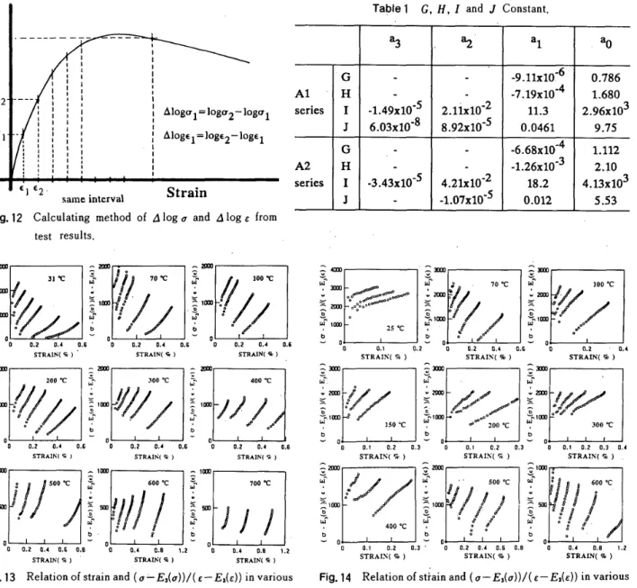
Figs.
10
and11
showthe
relationshipbetween
A
log
a andA
log
E of some examples.The
A
log
a andA
log
sare explainedin
Fig.
12,
It
appearsthat
there
is
approximately alinear
relation$hip.On
the
basis
ofthis
relationship,it
'
can
be
expressed asfollows:
'
a=aEbexp(cE)・--・・・・・・・・・・・・・・-・・・-・・・・・・--・・・・・:-・・・・・・・--・・・-・・・・-・・-・・・-・・・-・・・--・・・-・・・-・・・・・・・-・・・・-・-・--・・・-・・-・・-・(7)
Where,
if
welet
a>O
and E20,the
equation(
7
)
passes
through
the
originin
the
caseb>O
andthe.
tangent
slope
of zeropoint
{
1ts)
changesby
the
magnitude ofparameter
"b".Hereupon,
parameter
"b"must
take
"1",in
orderthat
the
initial
tangen,t
modulus
of
elasticity
may
have
an
arbitrary value,This
is
asfollows,:
k=a
atb-1・---・・・-・・-・-・---・---・-・-i・-・・-・t--・---(8)'
Besides,
a
parameter
"b"and "c" must
be
the
opposite sign,providecl
that
E(T)ma. musthave
positive
value.Therefore
''
'
E(T)max='-11c at c<O・・・・・・・・・・・・・・・-・・・・・・・・・・・・・・・・・・--・--・・・・・・・-・・・・・:・--・・・・・--・・・-・・・-・・・-・・・-・・・・-・・-・・・・・・・・・・・<9)
a(T).ax=ae(T)ma.exp(-1)・・-・・・・・・・・-・・・-・・・・・・・-・・・-・・・・・・・・・-・・・・・・・・・・・・・-・・・・・・・・・・・・・・・・・・・・・-・・・・・・・・・・・・・・・・-・・-・・・・(10)
a=a(T)ma.fe(T)ma.Xexp(1)'・・t・''''・・・・・・・・・''・'・・-・・・・・・・・・-・・・・・・''・・・・・・-・・・・・・・・・・--・・・・・・・-:・・-・・・・・・・--・・・・・・・・-・・・-・{11)
Therefore
the
relationshipbetween
stress and strain of envelope curve canbe
expressed asfollows
:
mmopk"m g2 al ,
1
il
--u
il Li ldlii
Ltd-
IId 1111 llllill
:Lltiil:
L e l 1 11/
l
4:
d l L l 1 1:
:
Alogalulogg2-logvl
i l:
:
AlogEl;]ogE2-logEl
d l b tl
eI
I
El E2・Strain
sarneinterv"1Fig.12
Calculating
method ofAloga
andAloge
from
test
results,:sum'
-mmo
..
at"Il/IP.7/z
'i℃l.`ff"ig,/j]I],
lll.iem!/2;T/
'OO=D O
o
b D.2 o.1 o.e D e.2 o.i o.6 n O,2 O.4 e.S
STRAIN[fi) STRAIpt("] STRMptC-]
: ttmo=.
..
ato-=mo
ieo℃ i- 3eo
"c
;・. 400℃'/li・--iii.<.2:/i/
lrmg///
i`-v/..
'
ee
o,2 o.4 o,e eo o.1 o,- e.F eo D.2 o.l o.t
sTRAINCfiJ stRA:N[g} STRAIN[-)
:1mn
-lun
-looo
=.S.
6oo ℃:'.
ToOT/
ll.s"n
!Zams..4/!
llLswfff
Vo
-o
o o,z o.4 o,s a:e o D.4 o.e ln v o,4 o.s ln
STR"IN{") STnA]N(S} STfiklS(N)
Fig.
13
Relation
of strain and(a`-E,{a))1(e-E,{E))
in
vaTioustemperature
(Al
series).TaPte1
G,
H,
l
andJ
Constant.
%
a2' al aoG
'
-
-9.11xlo-6O.786
AlH
-
-
-7.19xlO
.4
1.680
.serlesI
-1.49xlO
-5
-2
2.11xlO
11.3
32.96xlO
J6.o3xlo'8
8.92xlO
-5
O.0461
9.7S
G
-
'
-6.68xlO
.4
1.112
A2H
-
.
-1.26xlO
-3
2.10
'serlesI
.3.43xlO
.5
-2
4.21xlO
18.24.13xlo3
J
-
-1.07xlO
-5
O.O12
5.53
..
,A
A-cu
-
t.
orm-SM
- -v. -. v./
il.i.Ii
f""':"'"e'"pt
1
ti . D'i/..Icl//
70 ℃i/..::
,yc];=O sTRft-;N(-) n-1 D sOT・!RArliS・i4%)"・C " sTROillN(-')aJ
-
-
-.
Arm
nrm
-t
rmtt・・
t
:-・
/
:ny
/
・
.gnm ';an.z.pt7f"gmm.V//ijioco
ij-imm
ee'b4:oo ℃tiian
3oo ℃b b b
v
VO
L.OO D.1 O,1 O.1 O O.1 O,2 O.1 O O,1 O.? O.1 O.4
STRAIN(5} STRA]h'C-) STRAIN{g)
-
-
---IMP
ur
Aam
ulAlam
wv
-
-
m--
--//,am
:"
,.;/
..OfiS
sg
`g400℃
i'e
it-
pt:beiS.f
elg
g
6:c.
V
o o" e,2 Q.sY o o2' o.a D,E o.H- Oo o.1 e,e i,2
STRATNCS) STRA[NCS) STRAIN{%)
Fig.
14
Relation
of stfain and(a-E,(a))!(s-Es{E)}
in
various
temperature
(AZ
series).
-・7
Architectural Institute of Japan
ArchitecturalInstitute of Japana(T)la(T)ma.=exp(1-e(T)le(T)mx)XECT)!e(T)rte.'H''''H''''''''''''''''''''''''''H'''''''''''''''''''''"'''H'''(12) where a<T)=Stress
(kglcrn2)
e(T)==Strain
(%)
4,2
Unloading
curveSome
examples
of
the
relationship
between
the
strains,
E,on
the
unloading
curve
andthe
secant
s]opes
aie
shownin
Figs.
13
and14.
The
secantslops
(a-E,{o))1(e-E,(e)}
arecalculated
from
the
E,
point
(See
Figl2)
andeach
point
onthe
unloaclingcurve.
Where,
E,(a)
(=
O)
andE,(E)
arethe
stressand
strain
ofE,
point,
respectively.It
appears
that
there
is
approximately
alinear
relationship.On
the
basis
ofthis
relationship,the
unloadingcurve
can
be
expressed as
follows:
a=de'+ee+f・-・-・・・-''・・・・・・・・-・・-・・-・・-・・-・・・-・・・-・・・・・・・・・・-・・・・-・・・t・・・・・・・・・・・・・・・・・-・・-・・・・・・・・・・-・・・t・・・・-・・(13)
where each
parameter
d,
e
andf
is
derived
from
experimental results accordingto
the
retationbetween
the
stress-strains of
E,,
E3
peints
andthe
tangent
slop of unloading curve atE,
point,
tan
e,
shownin
Fig,2.
The
strainand
the
tangent
slope
(tan
e)
ofE,
peint
mustbe
related
withthe
function
of
the
strainef
E,
point,
in
order
to
fix
the
unloading curve.They
canbe
expressed asfollows:
E3{E)=G'Ei(e)"''-'・・・'''・・・・・・'''--・・・"'・-・・-・・t・・・・・・・・・・・-・・・・・・・-・・t・・・・・・・-・・・--・--・・-・--ny・-・・-・・・・・・・・・・-・・--・--(14)
Y}=I・exp(J・E,(E))・・・・・・・-・・・・・・・-・・-・・・・-・-・・・・・・・・・・t・・・・・・・・・・・・・・-・・・・・・・・・・・・・・t・・-・・・・・・・-・-・・・・・・--・・-・・-・・・・-・--・・(15>
where
G,
H,
l
andJ
arederived
from
experimental resultsby
the
use ofleastsquares
regression and regression equationsare
estimated
aspolynomial
expressionsas
for
temperature.
G,H,I
andJ==Za,T`--・・・・-・-・・・-・---t-・----・・・-・--・---・・--・・---・・・-・---・-・---・(16)
T=Temperature
(OC)
The
coefficients
(aD
areshown
in
Table1,
E3(E)=Strain
ofE,
point
(%)
E,(e)=Strain
of startpoint
(E,)
of unloading curve(%)
Yl=Tangent
slepe(tan
e,)
ofE,
point
(kglcmZ)
4,3
Reloading
curveThe
reloading curves are assumedto
be
linear
equationspassing
through
the
points
E,
andE,
shownin
Fig.2.
a=ge+h''"'H""""'""H""""'-"'"-""v"H"""''""'""'H-"'H"'"H"""H""'""H-"-''"・'-"""(17)
Therefore,
the
stress
and
strain
of
E!
point
mustbe
known
for
deciding
a
straight
line.
The
strain ofE2
point
is
derived
from
expe[imental results asthe
functien
of strain ofE,
point.
E,{E)=K・E,CE)-・・--・・・・・--・・-・・・・・・・・・-・・・・--・-・・・-・・・・・・・・--・・-・・--・・・・・・-・・・-・・-・・・・・・-・・・・・--・-・l-・・-・・・-・・・・・・(18)
where
K=2.
81
×10J5
T+O,
969
for
Al
seriesK=5.
63
×10-5
T+O.
950
for
A2
seriesEi(e)=Strain
ofE,
point
(%)
The
stress ofE2
point
canbe
obtainedby
the
equationof
unloadingcurve
atthe
strain ofE,
point,
5.
Stress-str4in
loop
during
unl6ading
and
relading
m
i
an
sm
1ca
o
a
e.t
o,2
e.eSTRAIN
t
Fig.
15
Experimental
stress-strain-8
O,4x)under O,5o.c cyclicloading.
-HfiRNxvuammatsua
1E3
sTRAng(
es)NII-Electronic Library Service
The
stress-strain relationshipof
concrete
under
high
temperature
is
neededto
predict
the
load
carring
capacity
andthe
deformation
of
membersof
reinforced concrete structures subjectedto
high
temperature.
The
investigation
of stress-strainloop
during
ttnloading and rcloadingis
necessaryfor
arational approachtb
the
problem
fo
inclemental
elasto-plasticdeformation
of reipforced concrete structures subjectedto
arbitrayloading
and variabletemperature
such
as
fife
condition.
And
the
shift rule of stress-strain relationship undei arbitrary varying stressis
necessaryfor
the
iterative
calculation method of convergeneein
elasto-plastic analysis.The
experimental Tesult ofA3
concrete underthe
conditions cyclicloading
within oneloop
at roomtemperature
is
sho)vn
in
Fig.15.
Ori
the
conditions
of
cyclic
loadings
within oneloop,
the
active movement of stress-strainfor
unloading.and reloading arisesinside
this
loop(Fig,
15),
And
reload-ing
cruves within oneloop
converge nearthe
common.'"
.E
point
(E,
point).
・
R.
x
On
the
basis
ofthese
phenomena,
the
felationships
of
zaV
ste.ss-strain
during
unloading and reloading at constante
m
temperature
are assumed asfoilows;
In
the
case ofFig.
16,
if
stressincreases
from
Ul
point
of unloading curve,the
stress-strain relationshipis
shifted onthe
straightLine
passing
through
Ul
andE,
'points.
Where,
E,
point
is
calculatedby
the
usep,f
equation
(19>
Csee,Fig.16).
m
''m
Fig.17
Shift
of stress-strainloop
during
reloading.(5-2
1"
m
}ps,Jm
il1]"vaptmO
,-g..!
,N -1-1}.pe ,. 1-Fri-t,U#rieH/al....Age,1."-.-. 1'11"'s..t
t
-x',,' f-v,,.,1,,,,lt,.',:`'1・i2"'r"l!
't'
.rv
,,,,,,,,/'1
''rfJ'/t" e Le -,i u L- tl ".1]ng-1cr
mi,.Iza/m
-o1,ms-"a m1}nlot laT-F/-tmNtts+e-eld--di"in't.r.L..t..tttth.L.t.'
'1't/tltttt''x'ttt!tttt.---.
,,・:,.I・r,,r`,t'z',tf,,'.t
xtt.t..t...-/E ee,/e,lo.]e.J.:" -ElEs. -b R1 {1:{2=al:a2 pt t2=if2X.EllCl b E3Ei"
E2 EE4,STRAIN(%)
-.m}el-=-q ms"l-E. t-Sd}neza p
m
mi-T'-e.
/m
1}mi'u /"'t-.
m=-bim-....
J-ded
.V"'
1
'ttt
-e Lt za4 eE L- 1 II SmaEnyt-1 matNCibFig.18
Experimental
ancl calcuiated resuLts of stress-straincurves
in
varioustemperature
(Al
series).m1?mge=m
rp}e
e"
/-n{e)me.tm
fiS.]ns=n
v
m{o] tte.,/"n1}ne-
stMISt1b nv1rii:/
Fig,19
Experirnental
ancl calculated results of stie$s-$tTaincurves
in
varioustemperature
(A2
series).Architectural Institute of Japan
ArchitecturalInstitute ofJapan whereet:E!-ai:ai-a!
1
Et==(ai-a})la,XE,
i
'H''--"''''""""""H"H'HH''HH'HHHMH-""''"'M-H"'''H"'H""---・-・・---・・・・-(lg)
Ei=E,<e)-Ei(e)
Et#Es{E)-E,{e)
'
ai,ar=Stresses of
Ei
andVl
points,
respectively(kglcm2)
Ei(e),E,(E),
Es(e)=Strains
ofE,,
E,
andE,
points,
respectivelyIn
the
case ofFig,
17,
if
stre$sdecreases
from
R,
point
of reloadingline,
the
stress-strain relationshipis
shifted onthe
quadratic
curvedetermined
from
the
stress-strainsof
R,,
E,
points
andthe
tangent
slope ofE,
point.
Where,
the
tangent
slope
ofE,
point
is
calculated usingthe
equation(15)
in
whichE,(e)
must
be
exchanged withthe
strain ofR,
point
and
E,
point
is
calculatedby
the
rateof
relationshipbetween
stresses ofR,
andE,
points
versus adifferenee
of
strams ef
E,
andE;
points,
asfollows
(See
Fig.17),
El:et=al:a:1
E!=ozlaiXEi
i
'''''''-''-'''''''''''''''-'''-''''''-'''''''''''H''H''H'''''''''''''"''''''''・-・・・・・・・・・-・・-・・・・・・・・・・--・-(20)
ank..:-:1oo
o anI.--zauza'1oo
oam
o
D.1O,lo,3 e.4STRA[N
C
X]O.5o.c o O,1O,2O.3 O,4sTFtArN'c
x
}.D,5O,6
anA
rm}.eanxmovzavta
or) 1co o an-mke
an:getsnm
e,1200
℃too
e e 02 o.s a.4STRAIN
C
X
)o.fiO.6
-xxm
mo:mgeta1caeo
Fig.
20
o e,1D.1o,s o,4STRAIN{X1eso,e
o.tCalculated
02
resultsO.3
O.4STM[NCr)
of stress-strainin
p.s2000C
(Al).
O.6A
anighx amvzawza ano 1oo o 200 ℃ o O.1O.2Fig.21
Calculated
resultsO.3 O,4
STRAINtX)
ef $tress-strainin
O.5O.6200"C
(A2),
-10-NII-Electronic Library Service
where e,=El(e)-E;(e)
e2=E,(e)-Es{E)
ai,a2==Stresses of
Es
andR,
points,
respectively(kglcm2)
Es(E),EZ(e),E4{E)=Strains
ofEl,
E:
andE,
points,
res'pectively
6.
Calculation
results
The
calculated results are shownin
Figs.
18
and19
comparing withthe
experimental results of some exarnples.This
calculated stress-strain envelope, unloadingand
reloadingcurves
arein
good
agreement
withthe
experimental
results,
The
calculated Tesults about stress-strainloops
during
unloading and reioading are shownin
Figg.
20
and
21
for
reference.
7.
Conclusions
Based
onthe
test
results andthe
mathematica! expressionpresented
onthis
paper,
the
following
conclusion$can
be
made;'
・
The
rnathematical expression ofthe
relationshipbetween
stress
andstrain
under cyclicloadings
at elevatedtemperature
has
been
developed
by
usingthe
experimental
results,Calculated
results usingthis
expression
arein
good
agreement
withthe
experimental results,The
comparativelygood
correlationbetween
predicted
and experimental stress・strain curvesindicates
the
adequacy of
the
expression
ofusual
andhigh
strength concrete,However,
further
experimental and analytical works are neededbefore
a moregeneral
mathematical expression canbe
formulated:
Reterences'
1}
・
Smith,
G.
M.
andYoung,
L.E.
,"UltiTrtate
Flexural
Analysis
Based
en
Stress-Strain
Curves
ofCylinders",
ACI
Jonrnal
Proceeding
Vol.53,
No.6,
Dec.
1956,
pp.597N609,
'
2)
Desayi.
P.
andKrishnan,
S.
, "Equationfor
the
Stress-Strain
Curve
ofConc[ete",
ACI
Jou[nal,
Pioceedings
Vol,
61,
No.
3,
Mar.
I964,
pp.345-350.
-3)
Sinha,
B.
P.,
Gerstle,
K.
H.
andTulin,
L.
G.
,"Stress・Srtain
Relations
forConcrete
Under
CycLicLoading",
ACI
Journal,
Pf6ceedings
VoL61,
Ne,2,
Fed.
1946,
pp.195N211,
・
'
4)
Popovics,
S.
, "ATe"iew ofStress-StrainRelationships
forConcrete",
ACIJournal,
Proceedings
Vol.67,
Mar.
1970,
pp.
243
-248.
5)
Maher,
A.
andDarw{n,
D.,
"MortarConstituent
ofCencrete
in
Compressien",
"ACIJournal.
Proceedings
Vel.79,
Mar.-Apr,
l982,
pp.100rl09.
6)
Furumura,
F.
,"Studies
on
the
Stress-Strain
Relatlon
ln
Cornpression
ofConcrete
atHigh
Temperature",
TTans,
of",
I.
J.
,
No.l72.
173,
174,
Jun.
Aug.
1970.
7}
Kozu,
S.
andSaiki,'
S.,
Sci.
Rept
Toheku
Univ.
(3)2,
1925,
pp.204-208.
-11-Architectural Institute of Japan
Arohiteotural エnstitute of Japan
【
論文
1
UDC :614
.
84
:691
.
32
日本建築学会構造系論 文 報 告 築 第3S4
号・
昭和63
年2
月高
温
に お け る
コ
ン
ク リ
ー
ト
の
応 カ
ー
ひ
ず
み
関
係
の
定 式化 (
梗 概
)
正 会 員 正会 員
正 会 員 正 会 員古
呉
安
金
村
部
* 纏
* * * ホ ホ ホ ホ
郎
煕
雄
中
次
福
昌
武
和
1,
序
高 温
に おける コ ン クリ
ー
トの力 学 的 特 性
は,原
子 カプ
ラ ント
のプ
レ スト
コ ンクリ
ー
ト圧 力 容 器
の開発
お よび火
災 時
の鉄 筋
コ ン クリ
ー
ト部 材
の挙 動
に関
する研 究
に関 連
して,
必要
に なっ て きて い る。高
温
に おい て コ ン ク リー
ト構 造 物
の挙 動
を明確
に解 明
す る た めに は, コ ン ク リー
トのい くつ かの基
本
的
な力 学
的 性 質
に関 す
る材 料 デ
ー
タ が 必 要
であ
る。
特
に,
応 カ
ー
ひず
み関 係
, クリ
ー
プ
,熱 膨
張等
を広
い温度 範
囲
におい て究 明
する こと
が大 切
であ
る。 その中
で, コ ンク リー
ト構 造 物
の変 形
に対 す
る部 材 内 部 応 力
の意 味 あ
る情 報 を提
供
する ために は, コ ン ク リー
トの応 カ
ー
ひず
み関
係
の数
学 的 な表 現 が 非 常
に重
要
であ
る。
鉄 筋
コ ン ク リー
ト部材
の極 限 曲 げ 解 析
など
に関 連
し,
多
くの研究
者
1}』
4} に よっ て, コ ン ク リー
トの応
カー
ひず
み関 係
に対
す る実 験
と数
学 的 解 析 が 行
わ れ て来
た。
し か し,高
温 で の繰
り返 し荷
重 下
におけ
るコ ンクリ
ー
ト
の挙 動 を究 明
し,火 災 時
にお ける変
動 応 力お よび変 動 温 度 下
で の鉄 筋
コ ン ク リー
ト構
造 物
の変
形 挙 動
を 工学 的
に解 析
し よう
とす
る研 究
はほと んど
行
わ れ ていない。本
研究
では, 高 温 時 にお け るコ ンク リー
トの応 カー
ひず
み関 係 を
,既
往
の実
験
結
果
6〕 か ら数学 的
に表
現
す ること を
目的 と
し た ものであ
る。
高 温 時
に お け るコ ンク リー
トの定 式 化
さ れ た応 力
二ひず み関 係
は,
火 災 時
に お ける鉄 筋
コ ン クリ
ー
ト構 造 物
の安 全 性 を確
かめ
る ため
に必 要
なも
の であ る。
2
.
試 験 方 法
応 カ
ー
ひず
み曲 線 を測 定
す る実 験
は,電 気 炉 を備
え た150ton
ユ ニ バー
サ
ル試 験 機
で行
わ れた。
載 荷 装 置
とひず
み計
の詳
細
をFig.
1
に示
す。
原 則
と し て,
温 度
は約
1
℃〆分
の速 度
で上 げ
た。試 験 体
の温 度 分 布
を一
定
に し,
熱 膨 張
およ
び収 縮
を避
け る た め に,
試 験 体
は1− 1.
5
時間
,
試 験 温 度
に保
た れ た。
試
験法
の詳
細 は文 献
6
}
に述
べ られて い るQ串
東
京工業
大 学教
ff
+
工博* * 韓 国 漢 陽 大 学
教 授
・
工博
# *東京
工業
大 学助 教 授
・
工 博 榊 榊 東 京工業 大 学大 学 院 生
・
工 修 {昭 和 62 年 3 月25
日原 稿 受理}熱
膨 張,重
量 減少
お よ び除 荷
,
再 負 荷 時
の応 カ
ー
ひず み ルー
プ を 求
め る た め に追 加
試
験
を行
っ た。実 験
に用
い ら れ たコ ン ク リー
トは,
A1
シ リー
ズ(
普 通 強 度
コ ン ク リー
ト)
の場 合
,
大
き さ5
φ×10
cm,
養 生
1
年
,
ポ
トラン ド セメ ン ト,
多摩
川
の骨 材 (
最 大 大
きさ
1cm
) 使 用
, セ メン トー
砂
一
砂利
比
1
:2
.
8
:2.
9
,WIC
70
%,
ス ラ ンプ
15cm
,強 度
238kg
/
cm2,
E
,/ 325.
2
×104
kg
/
cm2 である。
A2
シ リー
ズ(
高強 度
コ ン クリ
ー
ト)
は大 き
さ5
φ
×10cm
,養 生
3
〜
4
カ 月, ポ ト ラン ドセメ ント
,
多 摩 川
の骨 材 (
最 大 大
き さ1cm )使
用
,
セ メ ン トー
砂
一
砂 利 比
1
:1
.
9
:2
.
0
,W
/
C
45
%,
ス ランプ
5
.
9cm
,強 度
457
kg
/
cm2 ,Eifs
29.
5
×104
kg
/
cm2 であ る。A3
シ リー
ズ(
追
加試
験 用 )
の場 合
は,
養 生
10
年
,
ポ ト ラン ドセメ ン ト,
多 摩 川
の骨 材 (
最 大 大
き さ1cm )
使 用
,
セメ ン トー
砂
一
砂
利
比1
:2,
8
:2
.
9
,
W
/
C
65
%
,
ス ラ ンフ15cm
,
強 度
235
kg
/
cmz,
Ei
/s20
.
1
×104
kg
/
cmt である。3.
応 カ
ー
ひず
み曲線
の形 状
繰
り返 し荷 重
下にお け る試
験体
の軸
方 向 変 形
は,
通 常
,
応 カ
ー
ひず
み曲線
によっ て表
現
で き る。 コ ン クリ
ー
ト
の応 カ
ー
ひず
み曲
線
はFig.
2
で見
ら れ る よ うに包
絡
,
除
荷
,再 負 荷 曲 線
の3
部 分
に分
け ること がで きる。
高
温時
の,
荷
重
作
用 下
にお け る鉄
筋
コ ン ク リー
ト構 造 物
の挙 動
を理
論的
に予 測
す る た めには, これ ら の曲線
の数 学
的
な表
現
が 必要
であ る。
通 常
,
コ ンク リー
トの応 カ
ー
ひず
み曲 線
の実 験 式
は,
最 大
応
力
,
最 大
応力時
の ひず
み,
初 期
こう配 等
の関数
と して,
指
数 型で表
さ れ るこ と が多
い。 し たがっ て,
いろ い ろ な温度 下
で のコ ン ク リー
トの包絡 曲線
を数 学 的
に表
現
する ために は,
これ らの変 数 を温 度
の関 数
と し て表
さ な け れ ば な ら ない。Fig
.
3,
4
の実 験 結 果
から
,
各
々 の変
数 と 温度
の関 係
をFig
,
5
,
6
,
7
に示
す。 これ らの実 験
式 を(
1
)
一
(
6
)
に示 す。
最 大 応 力
,
最 大 応 力 時
の ひず
み,
最
大 応 力
の1
/
3
で の割 線 弾 性 係 数
は温度
の増 加
によっ て変
動 す る。最 大 応 力
は100
°
C
付
近で減 少
し,200
℃近
くで ま た増 加
す る。200
℃ か ら400
℃ の温度
に お け る最 大 応
力 は あ ま り変
一
12
一
NII-Electronic Library Service
動
しないが,
そ の後
700
℃
ま で急 激
に減 少
する。
こ れ らの現 象
は,
主
に コ ン クリ
ー
ト内 部
の自 由 水
や化 学 的 結
合 水
の蒸 発
,
セメ,
ント水 和 物
の変 化 や 大 抵
の骨 材
に含 ま
れてい る石 英
の結 晶 構 造
の変 化
にょる膨 張
に関係
し て い る と考
え ら れ る。同
じ材 料
か ら なる ほ か の コ ン クリ
ー
ト試 験
体 {
A3
シ リー
ズ
)
か ら得
ら れ た重
量 減 少
と熱 膨 張
の試 験 結
果によっ て,
こ れ らの現
象
が あ る程 度
理解
で き る(
Fig.
8
,9 )
。
す な わ ち, 室 温か ら100
°
C
お よ び400
°
C
か ら700
℃ の温度 範
囲 に お け る コ ンク リー
トの重 量 減 少 と
400
℃ か ら600
℃ に お け るコ ンク リー
トの熱 膨 張
の変
動
は,ほ か の温度
範
囲に比べてか な り大
きい。最 大 応 力 時
のひず
み は 温度
上 昇
と共
に増 加
す る。弾 性
係 数
は温 度 上 昇
と共
に減
少
し,
特
に室
温か ら100
℃ の温
度
で著
しい減 少
を示
してい る。除 荷 曲
線
は2
次 曲
線
の形
状
を示
し,再 負 荷 曲 線
は塑 性
ひず
み の大
き さに よっ て その形 状
が変
わる。
また,
これ らの曲 線
の こ う 配は, 温度
や除
荷
曲 線
の ス ター
ト位 置
の ひず
み によ
っ て大
き く変 化
す る。
4.
数 学 的 解 析
コ ン クリ
ー
トの一
定 温 度 下
に お け る応 カ
ー
ひずみ関 係
を3
部 分
に分 け
て表 現 す
る。4
.
1.
包 絡 曲
線
Fig.
10
,
11
にA
log
a とAlog
εの関
係 を 示 す.
A
log
σ と △