Japanese Physical Therapy Association
NII-Electronic Library Service
JapanesePhysical Therapy Association
pp\st
iX\
eg
33
ts
eg
4
U'・
220
-
222
H
(2006
ff・)
mp\fitagesxep7thnjmzaesft
Quantitative
Evaluation
of
Gwang-Moon
EOM
"*
lntroduction
Spasticlty
is
known
as ahypersensitive,
dent
responseto
passive
muscle stretch-.In
manypatients
with stroke. spinat eord
injury,
cerebralpa]sy
patients,
ticity
refiectsdamage
to
the
central nervous systernthat
liinits
their abilityte
walk andperfurm
finc
rriovementsed
for
work a]d recreutioT]2),
Mest
traditienal clinica] assessmcnls of spasticityfor
uatien ofthe
therupy
effecthave
been
qualilatTve
in
nature.rL・tcasurcs
such nsthe
]v'Iodifiad
iXsh"'orLhScale
(}vl.,IS)3),
don
Laps,
and strctch refiextests
rely onthe
judgtnent
of cxaminerin
assigning a x,aluete
theindividual's
degree
of spasticiL},.
Recently,
mathematical approachesto
this
assessmenthave
been
sLtggested5 ii).iXmongthese,
pendulum
testS
iD
is
ene ofthe
most simple measurementfor
clinicai tion,so tharthis
paper
cleals
withthe
quantitative
inent orLhe
spasticity withpendLiluni
test.
The
main ture ot'this
paper
is
twofotd.
One
is
the
suggestion oftic
joint
torque
model asthe
delayed
feedbaek
of muscle
length
andtengthening
velocity. whichis
thought
tu
be
iologicatty
feasible,
The
otheris
to
medelthe
knee
joint
asthe sum of
intrinsic
(mechunical)
purt a"d spasticpart
andthen
identify
each partin
series,Through
this,
",e couldfind
the parumeters ofthe
spusticfeedbuck
system whichcan rcproduce
the
cxperimantalpcnduluin
trajectory
olpauents.
Methods
The
spasticity ofLwo
strokepatients
wastested
in
this
paper,
svhosct anthropometricdata
is
shownin
Table1.
As
sho",n
in
Fig.1,
the subjects were setin
supine position.EMG
frem
quadriceps
muscle and theknee
joint
angle wasmeasurecl
during
the pendulum test.As
theinitiat
postureSpasticity
ChuL-Seung
with
Pendulum
Test
*
Kim
Se-Jin
Kong
Table
1
The
information
ofthe
subjectsSubjeet
Age
SexW'
eightIIeight
MAS
(K.v)
(cm)
AB
6657FF
8145
17115S
11
'
N'EIrtzaAtckigg・[rka)kfiptrm
'*
BiomeclicaL EiLgineering,Konkuk University,
Choongju,
Korea
E{nni1/[email protected]
Key ii'ords/ spasLicity, pendulum test,
feedback,
muscieiength,
lellgLhening
velocity
Patient
EMG
EMG
Meas,
/
i
System
MagneticGeometiCdata
Liberty
,
.
sy.st.e.
n.
:
Motion
.Video
Capture
System
Fig.
1.
Block
diugrarn
experirnental sctupof
the
pendulum
test,O,
15,
30
dcgrec
freni
fuLl
extensien were used.
The
joint
torque ufknee
joint
is
modelc/d as summationof the
intrinsic
one andthe
spastic u"e asin
Fig.2
and eq.(]}.
The
intrinsic
torque
is
eerriposed of those coiningfi/oni
gravity,
nonlineurdainper,
and nonlinear spring asTn
eq.(2).
Finully,
the
spastictorque
is
medeled as thedelayed
feed-baek
ofthc/
muscLelength
andthe
lengthening
velociry asin
eq.(3),
IIere,
the mLtsclelength
is
substitutedby
the
knee
joint
angle andthe
lengthening
velocityis
substituiedby
the
joint
angular s,elocityfor
sinipticity."ie
made adaring
hypothesTs
that
the
niusclelength's
rotein
spastic refiexis
only setting athreshold
andthe
relative magnitude of the spastictorque
ts
modulatedby
the muscleleT]gthening
veloc-ity.
e=(Ti.t+T,・)・'J
(1)
Ti.t:
intrinsic
torque
7L.:
spasticitytorque
I:
moment ofinertia
7L,,t=GsinCLDO"+ki(e'1"2(e'eRO"}-1)
{2)
G:
Gravitv
coefficientD/
Damper
coeft'icientki,
k2/
spring coefficientn/ nonlinear
damper
index
Japanese Physical Therapy Association
NII-Electronic Library Service
JapanesePhysicalTherapy AssociationQuantitative
Evaluation
of Musclelength71.t
MuseleLengthenangveloc/tyFig.
g!ocsEgEgJasss"
2.
sn4020 o20604020 o-?ofio4020 o-2n 50::
r:
s:."-,::g 2,: s:::
l:
o TaSpasticity
EOso ao
gse
:'en.i・]
( 10 o
.10
Fig.
Block
diagram
ofk"ee
joint
model$ublectA 5n 4D 3)
?l
o 50 40ts
u
30・--I:
g
o [・ot a
.=
=gli
Ori234S6 Time[sec]Fig.
4.
Simulation
modeL&
aetive term output
Subjcct
A,
right:Subject
B)
o o o
n60T
4o!202o2ligww
E:.X
20V.2:S
-4o"::8"
20g.,:S-ao
and 30 ?e withPendutumTest
o a r3.
Experimental
pazrern
3
knee
joint
221
fia D3 Vl u'iF £
to,
g
-c/.:2,Z3..1 4
4 i
o
Time[seclangle trajectory
&
E}L・IG
Eivl・,,
k.
Subject8
M/v""-.
o,o os a,o 1,s 2o 2,s 3,o
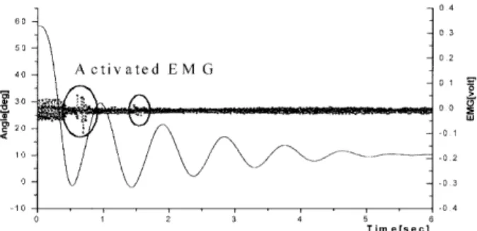
Fig.
5.
EMG
35 4,O 1]Eltterll-o-c
oe.U.oMU.ObSma ooo-o.o 4,5 50 5,5 G.D Trme[sec] versus actlve 08Odoo04osDSD4H
EDO
LOB04oo04osterm
fk(t-Td}=Agu(qh-e・(O,h-O)
(3)
A.:
spasticitygain
r(
)1
rampfuncrion
u():
Lzni[stepfunction
ah/
angiethreshold
eth./
angular vetocirythreshold
To
identiry
the
parameters
orthe
knea
joint
medel, wedesigned
two-step
methodto
sax,ethe
senrchingtlme.
The
first
stepis
the
identificarion
of rhelntrinsic
inodelpara-meters using only
the
tatrer
part
ofpendulum
data
where no spasticEbv・IG
is
shown asis
clearin
Fig.
3.
The
second stepis
to
identify
the spastic reflexparanierers
andfine
tun-ing
ef theintrinsic
parameters
using the whole range of024 experimental 3C2Maoo30
.b.2o
:ao .a,o302010D s s fo a2 T;me[sec]knee
juint
trajectory
(ieft/
oe 04
.oo
ao OC4 O.O08
3o meeg /be2o otsg
Sn
1OIotoO"S
o-ooe
ao ooB D04 20 ooo 10
-on4
o.ooe
Oa!345678g tO 11 12 Time{sec]output
(left/
Subject
A.
right/Subject
B}
pendulum
data.
As
the
cosrfunction
ofthe
parameter
search, normalizedRMS
errerberween
the experimental andlated
joint
angletrajectories
wus used,
Results
and
Discussion
Fig,4
shewsthc
simulation result withidentified
niodclparametcrs
in
subjc/cl t'X andB.
The
simulatedjeint
angle
trajcctorTcs
malch wcll ",iththe
cxparimcntal oncs.Fig.4
also sho",sthe
spasLicjoint
torque
appearTng at the end ofthe
first
falting
oflower
leg.
These
spastictorque
partern
matches well with
the
Etv・IG
activityin
quadriceps
musclein
i/lg.
5.
The
EMG
activiryprecedes
rhe spastictorque
in
the
figure.
whichis
justified
by
the
neuremuscutardetay
in
the
muscle.Japanese Physical Therapy Association
NII-Electronic Library Service
JapanesePhysicalTherapy Association222
Table
ve\:utza\
ig33gng41;
2
Coinparison
ofthe
seurchedpussive
&uctive
parameters
c
r)
R,
k2
neRo,Tfw##cg#gg#::ggg#ggeeggg・NMRSE
SubjectA
t.tt29.07861.41881.35284,6419O.7244-24.0909.$gee#g$g$ee$#$#egeeO1418
B
32.4759O.64823.49.772,3759O.553125,5611$geeg#gg$ee#l$xg$geeO.1269
The
identified
modelparameters
are shownin
Table2.
The
musclelength
threshold
e,b
is
simllarin
both
patienis.
The
musctelengthening
velocitythreshold
e,h
of subjectB
is
about1.5
times
of subjectA.
whichindicates
the
spas-ticity
of subjeetA
is
more severethtm
that
of subjectB.
The
spastic gain of each subjectis
notthought
to repre-sentthe
spasticdegree,
beeuuse
the
difference
in
maximum musc]eforce
in
each putient might affect the spastic gain.Therefore,
we suggestthe
rnusclclcngthening
ve]ocitythreshold
e,h
as theindex
of eachindividual's
dcgrce
ef spasLicity.
Conclusion
ln
this
study, wedesigned
a new model of spasticity andidentified
the spastictorque
of two strokeparients.
Though
the
MAS
of two patients were same, theldentified
spasticparameters
differed.
Especially,
the
musclelengthening
vetoc-ity
threshotd was suggested asthe
goodindex
ofthe
spas-tic
degree.
References
D
Rymer
"/Z,
Katz
RT/
Mechanism
ef spastichypertonia.
Phys
Med
Rehabil
8/
441
454.
1994.2} Delisn
JA/
Rehabilitatien IIedicine, 2nd ed. Phi]adelphia,JB
LippincotL, 1993.pp.660-6SO.
31]
Bogannon
RW',
Metlissa
BS/
Interrater
reliabiiity of a modit'iedashworth scalc ef muscLc spasticiry.
Phys
Tber
67/2eS-207, 19S7.4)
Hass
BM,
Bergstrom,
E,
et al:The
interrater
reliabMty of the originaa and ef thc modificd ashworth scalefor
the assessmcntef spasticity
i"
patic"ts with spinal cordinjury.
Spinal
Cord
8/
441
454,
1994.
r))
Aknlan
)・IN,
Bengi
R,
etal:Assessment
of spasticity using
kinetic
dynamometry
in
patients -vith spinal corclinjury
SpinaL
Cord
37/
6:38-643.
1999,
6)
Lamentagne
.,'X.
N'inlouin
F,
et al:Evaluarion
of rcflcx andrelfex
induced
muscLe resistance tostretchin
adults with spinalcord
injury
usinghand
held
undisokineLic
dyiLainunietry.
i'hys
Ther
78/
961-975,
1998.
7')
Sko]d
C,
Harms-Ringdahl
K.
etal./Simuttaneous
Ashwortb
surements and electermyegraphic recerdings
in
tetraplegic patients.Arch
Phys
pt{ed
Reliabil
Sl/
9S9
96,'),
2eOO.
81)
Bajd
T,
Vodovnik
L/
1'etiduluin
testi"gef spHsticlty.J
Bioined
Eng
6/
9-l6,
i98d.
9)
Lin
DC.
Rymer
WZ/
,'X quantitativc ana]ysis of pendular motionof thc
lower
leg
i"
spastichuman
subjects,TEEE
Trans,
Biomed
Eng
3S,
906
91S,
1991.
10)
Fee
jlV
Jr,
F{]uld
RA/
Neuroniuscnlnr
illodeLTng ef spnsticityin
cerebrat patsy.
IEEE
Trans
Neural
Sys
&
Rehab
Eng
12/
55-64,
2004.]1)
C/avorzin
PL,
Peudens
SiN,
etal./ ,X comprehensive modcl oftic
hypertoiiia
derived
frem
thependulum tc/stef theleg.
N'Tus{'}e
&
Nerx,e
24,
1612-l621,
2001.
12)
Eotn
Gts,L
Lee
S,l,
et al./A
new inethod ef theidentMcaLion
ot
joint
mechanicat properties.J
Korea
Society
ofPrecision
Eng
21/
209-218, 2004,
]3)
Eom
GN,I,
I.ee
CII,
et al:No"linear
damper
:nodelfor
the tificntionofjoint
Tnechanicnl propertles.J
Korca
Sec'iety
of
l'recision
Eng.
22/
l8S-l93,
2004.
t4)
LN'inLer
DA/
AnLhropoiiieLry.
In/
l・S"inter
DA
(ed),
Biotnechanics
and