ディジタルPID制御によるアンチロックブレーキシ ステム−アンチロックブレーキシステムのモデリン グ−
著者 青木 立
雑誌名 東京都立産業技術高等専門学校研究紀要
巻 12
ページ 26‑30
発行年 2018‑03
URL http://id.nii.ac.jp/1282/00000223/
Creative Commons : 表示 ‑ 非営利 ‑ 改変禁止
ディジタル PID 制御によるアンチロックブレーキシステム
–
アンチロックブレーキシステムのモデリング–
Antilock Braking System by Using Digital PID Control
– Modeling of Antilock Braking System –
青 木 立1)
Tatsu Aoki
1)Abstract:In order to stop a vehicle suddenly, a tire or a wheel will lock during braking. Since a vehicle slides on a road surface, it takes long time to stop a vehicle. Since a tire cannot transfer lateral traction forces, a vehicle motion becomes unstable and the handling performance becomes low. Thus, antilock braking system(ABS) is used to control the damping force of a brake so that a vehicle can be prevented from locking after brake torque is applied. Though Simulink models on ABS are downloadable from an internet, the detailed description of the dynamic model is left to users. The aim of this paper is to obtain a detailed dynamic model of ABS by using Simulink so that a new control algorithm for ABS can be developed. As an illustration, ABS based on a digital PID control law is considered. Simulation results show that the effectiveness of ABS with PID control is verified, since the stopping distance becomes about 68% in the case of a constant brake force.
Keywords: Antilock Braking System(ABS), Slip ratio, PID, Quarter car model, Digital controller
1. はじめに
車両運転における急ブレーキ操作では,タイヤや車輪が ロックして路面やレール上を滑ってしまう.その結果,車両 の停止に時間がかかるだけではなく,車両の運動が不安定に なり,ハンドル操作が困難になる.タイヤや車輪がロックし てスリップしないようにブレーキの制動力を制御するのが Antilock Braking System(ABS)である.ABSを実現するため の手法は種々提案されている[1].PID制御,最適制御,適 応制御,ロバスト制御,ファジィ制御などがABSに応用さ れている.一方,電気自動車(Electric Vehicle, EV)の普及が 今後さらに加速していく状況である.EVに搭載されている 電気駆動モータの応答性能は高いため,電磁ブレーキを利用 した高性能なABSが容易に実現可能になってきている.最 も簡単なABSはPID制御に基づきスリップ率を一定値に保 持する手法であり,その有効性が示されている[2][3].ABS をシミュレートする環境は,Simulinkのサンプル例としてイ ンターネット上に公開されている[4].しかし,このサンプ ルブロック線図では,タイヤや車輪のダイナミックモデルに 関する詳細な記述はユーザーに委ねられている.
そこで,本研究では,ABSの新たな制御手法を考案する ため,車両をモデル化し,シミュレーション環境を構築する ことを目的とする.モデル化された車両に関するABSの例 として,最も基本的なスリップ率に関するPID制御系を考え
る.Simulinkを用いたシミュレーションを実行し,その有効
性を検証する.
1)東京都立産業技術高等専門学校 ものづくり工学科 電気電子 工学コース
q
x m r
J
f
xf
Nu
Fig. 1 Quarter car model 2. 車両の数式モデルの導出
ABS制御系を構築するため,制御対象の数式モデル,す なわち,運動方程式を導出する.図1に最も簡単な1/4カー モデルを示す.質量m kg,半径r mのタイヤが水平面上を 回転しながら右方向に進んでいる.タイヤにはブレーキによ る制動力,すなわち,回転モーメントu N,水平面からの摩 擦力fxN,垂直効力fNNが作用している.タイヤの重心の位 置をx m,その回転位置をθradとする.なお,タイヤの回転 方向及び回転モーメントの方向は,時計まわりの方向を正と する.タイヤの重心速度x˙とタイヤの設置面の速度rθ˙が異 なる場合には,タイヤは水平面に対して滑っている状態とな る.そこで,スリップ率λを
λ=x˙−r˙θ
˙
x (1)
と定義する.タイヤが滑っている状態(λ >0)と滑っていな い状態(λ=0)で運動方程式が異なるのでそれぞれの場合に ついて考える.
• λ=0の場合
タイヤの水平方向には,ブレーキによる制動力u及 び水平面からの静止摩擦力fxが作用している.静止摩 擦力は静止摩擦係数µ¯を用いると
fx < µ¯fN (2)
と表現できる.剛体の運動は重心の並進運動と重心ま わりの回転運動で表現されるので,以下の運動方程式 が得られる.
m¨x = fx (3)
Jθ¨ = u−rfx (4)
スリップ率が0のときには
˙
x−rθ˙=0 (5)
が成立する.式(5)を時間で微分すると以下の関係式
¨x=rθ¨ (6)
が得られる.式(3),式(4),式(6)より静止摩擦力fxが 制動力uの関数として求まる.
fx= mr
mr2+Ju (7)
式(7)にタイヤの慣性モーメントmr2/
2を代入すると,
式(3)及び式(4)から¨x及びθ¨は以下になる.
¨
x = 1
m 2 3 u
r (8)
θ¨ = 1 J 1
3u (9)
式(8)及び式(9)よりタイヤの重心の移動速度x˙及び回 転速度θ˙はu=0 Nmの場合には一定になり,ブレーキ による制動力をかけた場合,すなわち,u<0の場合に は,両者とも減速していき,最終的に静止することがわ かる.
• λ >0の場合
タイヤの水平方向には,ブレーキによる制動力u及 び水平面からの動摩擦力fxが作用している.動摩擦力 は動摩擦係数µと垂直抗力fN=mgより
fx=−µmg (10)
により表現される.ここで,gは重力加速度とする.式 (10)に示す動摩擦力を考慮すると以下の運動方程式が 得られる.
m¨x = −µmg (11)
Jθ¨ = u+rµmg (12)
式(11)及び式(12)から¨x及びθ¨は以下になる.
¨x = −µg (13)
θ¨ = 1
J(u+rµmg) (14)
式(13)より重心の速度x˙は,ブレーキの制動力uによ らず,動摩擦係数µのみに依存して減速し,静止する.
0 0 . 2 0 . 4 0 . 6 0 . 8 1
0 0 . 5 1 1 . 5
Friction coefficient
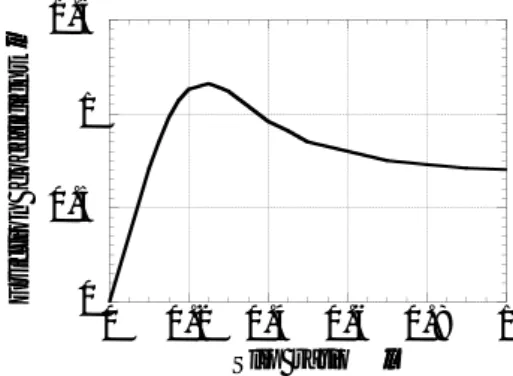
Slip ratio l
m
Fig. 2 Dynamic friction coefficient
一方,重心の角速度θ˙は,ブレーキの制動力uが動摩 擦力による回転モーメントより大きい場合には減速し,
最終的に静止する.ところで,図2に示すように動摩擦 係数µは,スリップ率λにより変化する[5].そこで,
式(13)及び式(14)は
¨
x = −µ(λ)g (15)
θ¨ = 1
J(u+rµ(λ)mg) (16) と記述される.また,動摩擦力fx及びブレーキの制動 力uは,タイヤの重心速度x˙及び回転速度θ˙が0にな ると作用しなくなる.これを表現するため,ステップ関 数f(x)
f(x) =
{ 1 x>0
0 x≤0 (17)
を用いて式(15)及び式(16)を修正する.
¨x = −f(˙x)µ(λ)g (18) θ¨ = 1
J
(f( ˙θ)u+r f(˙x)µ(λ)mg)
(19) 式(18)及び式(19)より求めた重心の加速度¨x,角加速 度θ¨を積分することにより,速度x˙及び角速度θ˙が求 まる.
˙
x =
∫
¨
xdt (20)
θ˙ =
∫
θdt¨ (21)
同様にして,重心の位置x,回転位置θが求まる.
x =
∫
˙
xdt (22)
θ =
∫
θdt˙ (23)
さらに,これらの速度x˙及び角速度θ˙に基づいてf(˙x) 及びf( ˙θ),スリップ率λ,動摩擦係数µ(λ)を求め,式 (18)及び式(19)にフィードバックする.f(x),スリップ 率の演算,λとµの関係は非線形のため,式(18)及び 式(19)に示す運動方程式は非線形システムになる.
以上より,ABSのシミュレーションでは,タイヤが水平面 に対して滑りがなく,定速で並進及び回転している状態を初 期状態として,制動トルクを加えた場合,すなわち,式(18) から式(23)を演算すればよいことがわかった.
Table 1 Dynamic friction coefficient
λ µ λ µ
0.000 0.00 0.35 1.04 0.100 0.71 0.40 0.96 0.125 0.85 0.45 0.91 0.150 0.98 0.50 0.85 0.175 1.07 0.60 0.80 0.200 1.13 0.70 0.75 0.250 1.16 0.80 0.73 0.275 1.14 0.90 0.71 0.300 1.12 1.00 0.70
l
rl q ˙
Controller
+ –
Brake system
Quarter car model
Slip ratio
˙ x
x
Sampler
e
Fig. 3 Antilock Braking System
PID
+
PWM
Zero-order hold Saturation
u
max0
–
1 e
+
u
max2
u
Fig. 4 Digital PID controller
3. シミュレーション結果 3.1 数値計算の安定性化
シミュレーションにはMATLAB/Simulinkを用いた.タイ ヤの質量mを15 kg,半径rを0.2 mとし,サンプリング周 期Tは1 msに設定した.また,図2に示す動摩擦係数µと スリップ率λとの関係は表1に示す点に関して線形近似し たテーブルを用いた.代数ループを避けるため,式(18),式 (19)におけるf(˙x),f( ˙θ)のフィードバック経路に0.1 msの 遅延ブロックを挿入した.さらに,式(1)に示すスリップ率 λを求める演算や重心の位置x,回転位置θを求める積分演 算の数値的安定性を向上させるため,重心位置x及び回転位 置θを求める演算に幅が0.01の不感帯を挿入した.図5に 最大トルクumaxを100 Nmの一定値に設定したときの応答 を示す.約0.1 sでタイヤの回転は停止するが,その後もタ イヤは水平面を滑り続け,0.58 sで停止する.停止するまで の移動距離xは1.139 mである.
3.2 PID制御に基づいたABSシステム
急ブレーキをかけてから車両が停止するまでの距離xを短 くするためには,式(18)から動摩擦係数µを可能な限り大 きくすればよい.そこで,図3に示すように動摩擦係数µに 関するフィードバック制御系を構成する.図4に示すPIDコ ントローラを用いた場合の応答を図6から図8に示す.
0 0 . 2 0 . 4 0 . 6
0 0 . 5 1 1 . 5
Vehicle position
Time s
x
m(a) Vehicle position x
0 0 . 2 0 . 4 0 . 6
0 1 2 3 4 5
Velocity
Time s
Vehicle velocity
Wheel velocity
x
m/s.
(b) Vehicle velocityx and wheel velocity r˙ θ˙
0 0 . 2 0 . 4 0 . 6
0 0 . 5 1 1 . 5
Slip ratio
Time s
l
(c) Slip ratioλ
0 0 . 2 0 . 4 0 . 6
- 1 2 0 - 1 0 0 - 8 0 - 6 0 - 4 0 - 2 0 0
Controller output
Time s
u
Nm(d) Control signal u
Fig. 5 Response in the case of constant force
0 0 . 2 0 . 4 0 . 6 0
0 . 5 1 1 . 5
Vehicle position
Time s
x
m(a) Vehicle position x
0 0 . 2 0 . 4 0 . 6
0 1 2 3 4 5
Velocity
Time s
Vehicle velocity
Wheel velocity
x
m/s.
(b) Vehicle velocityx and wheel velocity r˙ θ˙
0 0 . 2 0 . 4 0 . 6
0 0 . 5 1 1 . 5
Time s l
l
rSlip ratio
l
(c) Slip ratioλ
0 0 . 2 0 . 4 0 . 6
- 1 2 0 - 1 0 0 - 8 0 - 6 0 - 4 0 - 2 0 0
Controller output
Time s
u
Nm(d) Control signal u
Fig. 6 Response in the case of P controller
0 0 . 2 0 . 4 0 . 6
0 0 . 5 1 1 . 5
Vehicle position
Time s
x
m(a) Vehicle position x
0 0 . 2 0 . 4 0 . 6
0 1 2 3 4 5
Velocity
Time s
Vehicle velocity Wheel velocity
x
m/s.
(b) Vehicle velocityx and wheel velocity r˙ θ˙
0 0 . 2 0 . 4 0 . 6
0 0 . 5 1 1 . 5
Time s l
l
rSlip ratio
l
(c) Slip ratioλ
0 0 . 2 0 . 4 0 . 6
- 1 2 0 - 1 0 0 - 8 0 - 6 0 - 4 0 - 2 0 0
Controller output
Time s
u
Nm(d) Control signal u
Fig. 7 Response in the case of PD controller
0 0 . 2 0 . 4 0 . 6 0
0 . 5 1 1 . 5
Vehicle position
Time s
x
m(a) Vehicle position x
0 0 . 2 0 . 4 0 . 6
0 1 2 3 4 5
Velocity
Time s
Vehicle velocity Wheel velocity
x
m/s.
(b) Vehicle velocityx and wheel velocity r˙ θ˙
0 0 . 2 0 . 4 0 . 6
0 0 . 5 1 1 . 5
Time s l
l
rSlip ratio
l
(c) Slip ratioλ
0 0 . 2 0 . 4 0 . 6
- 1 2 0 - 1 0 0 - 8 0 - 6 0 - 4 0 - 2 0 0
Controller output
Time s
u
Nm(d) Control signal u
Fig. 8 Response in the case of PID controller
Table 2 Comparison of different types of controllers Controller Stopping time [s] Stopping distance [m]
− 0.58 1.139
P 0.38 0.786
PD 0.38 0.782
PID 0.38 0.785
なお,制御量uは飽和要素を用いてブレーキの発生可能な最 大トルクumax以内に収まるようにし,umax/2を動作点の中心 にする.さらに,1000 HzのPWM波に変換し,ブレーキシ ステムの入力とする.ブレーキシステムは,極が−50,DC ゲインが1の1次系とした.式(24)にディジタルPID制御 則を示す.
C(s) =kp
( 1+kd
1−z−1 T +ki
T z−1 1−z−1
)
(24) kp=1000,kd=0.01,ki=1.0とし,サンプリング周期Tは1 ms に設定した.図6に示すP制御では,スリップ率λが目標に 対してオーバーシュートしており,制御量uは振動的になっ ている.図7に示すPD制御では,微分項の効果でスリップ 率λに関するオーバーシュート及び制御量uの振動が消滅 している.図8に示すPID制御では,λに関して僅かなオー バーシュートが見られるが,PD制御の応答とほとんど変わ らない.これは,スリップ率の目標値λrに関する定常偏差 が小さいこと,さらに,積分項の積分時間を1 sに設定した ため,その効果が十分確認できなかったと考える.表2に各 制御による車両が停止するまでの距離xと停止するまでに要 した時間を示す.P制御,PD制御,PID制御における差異 はないが,ABSにより,車両が停止するまでの距離xが制動 トルクが一定の場合の約68%になることがわかった.
4. 結 論
ABSの新たな制御手法を考案するため,車両を最も簡単な クォーターモデルとしてモデル化し,Simulinkによるシミュ レーション環境を構築した.制御例として,スリップ率λr
を目標値としたディジタルPIDフィードバック制御系を構成 した.シミュレーションの結果,車両の停止距離についてP 制御,PD制御,PID制御について差異はなかった.しかし,
ブレーキシステムへの負荷の観点から操作量が振動的ではな いPD制御,PID制御が優れていることがわかった.
5. 参考文献
[1] A.A. Aly, E.S. Zeidan, A. Hamed, F. Salem, “An antilock- Braking systems (ABS) control:a technical review,” Intelli- gent Control and Automation, 2, pp.186–195, 2011 [2] C. Jain, R. Abhishek, A. Dixit, “A Linear control technique
for anti-Lock braking system,” Int. Journal of Engineering Research and Applications, 4-8, pp.104–108, 2014 [3] P. Rohilla, Jitender, Amit, A. Dhingra“Design and anal-
ysis of controller for antilock braking system in mat- lab/Simulink,” Int. Journal of Engineering Research Tech- nology, 5-4, pp.583–589, 2014
[4] https://jp.mathworks.com/help/simulink/examples /modeling-an-anti-lock-braking-
system.html?requestedDomain =jp.mathworks.com [5] https://www.weblio.jp/content/%CE%BC%EF%BC%8Ds
%E7%89%B9%E6%80%A7

![Table 2 Comparison of different types of controllers Controller Stopping time [s] Stopping distance [m]](https://thumb-ap.123doks.com/thumbv2/123deta/6815240.2232328/6.892.129.382.137.577/table-comparison-different-controllers-controller-stopping-stopping-distance.webp)
