[Title] Precautions when Replacing the GT14 Model with GT2505-VTBD
[Date of Issue] February 2018
[Relevant Models] GOT1000 Series (GT14 Models)
→
GOT2000 Series (GT2505-VTBD)
Thank you for your continued support of Mitsubishi Graphic Operation Terminal (GOT).
We released GT2505-VTBD of the GOT2000 series with high functionality and performance as an alternative of
the GT14 model in August 2017.
We highly recommend that you replace the GT14 model with GT2505-VTBD for using new sophisticated
features.
Contents
1. Requests for customers ... 2
2. Replacement models ... 2
2.1
GOT ... 2
2.2
Communication unit... 2
2.3
Option ... 3
2.4
Cable ... 3
2.4.1
RS-232 cable ... 3
2.4.2
RS-422 cable ... 3
2.4.3
Other cables ... 3
2.5
Software ... 3
2.6
License ... 4
3. Comparison in specifications ... 4
3.1
Comparison in hardware specifications ... 4
3.1.1
Performance comparison between the GT14 model and GT2505-VTBD ... 4
3.1.2
Comparison in power supply specifications between the GT14 model and GT2505-VTBD ... 6
3.2
External dimension comparison ... 7
3.3
Panel cutting dimension comparison ... 8
3.4
Mounting intervals ... 9
3.5
Function specifications ... 10
3.5.1
Comparison in functions ... 10
3.5.2
Detailed comparison in functions ... 11
3.6
Screen design software specifications ... 18
3.6.1
Preparation before converting the project data ... 18
3.6.2
Procedure for the project data conversion ... 18
3.6.3
Screen design functions that are not supported ... 20
We released GT2505-VTBD with high functionality and performance as an alternative of the GT14 model in
August 2017.
We highly recommend that you replace the GT14 model with GT2505-VTBD for using new sophisticated
features.
For the replacement models, refer to the following.
➟
2. Replacement models
2. Replacement
models
Other models can be selected depending on the usage status in your system. Select an appropriate model after
carefully considering the range of performance in the current system.
For the GT2505-VTBD specifications, refer to the following.
➟
GOT2000 Series User's Manual (Hardware) (SH-081194ENG)
2.1 GOT
Table 2-1 Replacement GOT models of GT2505 from GT145□
○
: Compatible, ×: Incompatible
GOT1000 series in use
Recommended GOT2000 series for replacement
Panel cut compatibility
Attachment necessity
Cable compatibility
Conversion cable necessity
GT1455-QTBD GT2505-VTBD ○ Unnecessary ○ Unnecessary
GT1455-QTBDE GT1450-QMBD GT1450-QMBDE GT1450-QLBD GT1450-QLBDE
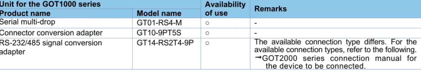
2.2 Communication
unit
The communication units of the GOT1000 series can be used together with the GOT2000 series as-is.
Check the availability of use in the following table.
Table 2-2 List of replacement models for communication units
○: Available as-is
×
: ReplaceableUnit for the GOT1000 series Availability
of use Remarks
Product name Model name
Serial multi-drop GT01-RS4-M ○ -
Connector conversion adapter GT10-9PT5S ○ - RS-232/485 signal conversion
adapter
GT14-RS2T4-9P ○ The available connection type differs. For the available connection types, refer to the following.
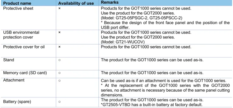
2.3 Option
For options, use the products for the GOT2000 series.
Some options can be used as-is.
Check the availability of use in the following table.
Table 2-3 List for option replacement
○: Available as-is ×: Not available
Product name Availability of use Remarks
Protective sheet × Products for the GOT1000 series cannot be used. Use the product for the GOT2000 series. (Model: GT25-05PSGC-2, GT25-05PSCC-2)
* Because the design of the front face panel and the position of the USB port differ.
USB environmental protection cover
× Products for the GOT1000 series cannot be used. Use the product for the GOT2000 series.
(Model: GT21-WUCOV)
Protective cover for oil × Products for the GOT1000 series cannot be used.
Stand ○ The product for the GOT1000 series can be used as-is.
Memory card (SD card) ○ The product for the GOT1000 series can be used as-is.
Attachment ○ Can be used as-is if an attachment is used for the GOT1000 series. * At the replacement of the GOT1000 series with the GOT2000 series, no attachment is necessary because of the same panel cutting dimensions.
Battery (spare) ○ The product for the GOT1000 series can be used as-is. *GT2505-VTBD has a built-in battery at factory default.
2.4 Cable
2.4.1 RS-232
cable
The currently used cable for the GOT1000 series can be used as-is for the GOT2000 series.
2.4.2 RS-422
cable
The currently used cable for the GOT1000 series can be used as-is for the GOT2000 series.
2.4.3 Other
cables
The currently used cable for the GOT1000 series can be used as-is for the GOT2000 series.
2.5 Software
To create project data for GT2505-VTBD, MELSOFT GT Designer3 (GOT2000), which is included with the
screen design software MELSOFT GT Works3 (Version 1.180N or later), is needed.
For how to obtain the software in a specific version, refer to the following table.
Software Supported version How to obtain the software
Screen design software MELSOFT GT Works3
■Japanese/English/Chinese version MELSOFT GT Designer3 (GOT2000), which is enclosed with MELSOFT GT Works3 Version 1.180N or later
The version shown on the left is supported. If your version is old, update the software to the latest version. For how to obtain the software, contact your local sales office. FA integrated engineering
software
MELSOFT iQ Works
■Japanese/English version Ver.2.48Q or later is supported.*1
The GOT1000 series licenses below cannot be used for the GOT2000 series.
Please purchase the GOT2000 series licenses.
Table 2-4 List of replacement models for license
○: Available as-is ×: Not available License name
(license key for GOT1000)
Availability of use
(license key for GOT2000) Remarks
License of the VNC server function (GT14-VNCKEY)
×
(GT25-VNCKEY)
Use the license for GOT2000.
* For how to authenticate the license, refer to the following.
➟
GOT2000 Series User's Manual (Utility) (SH-081195ENG)
3. Comparison in specifications
3.1 Comparison in hardware specifications
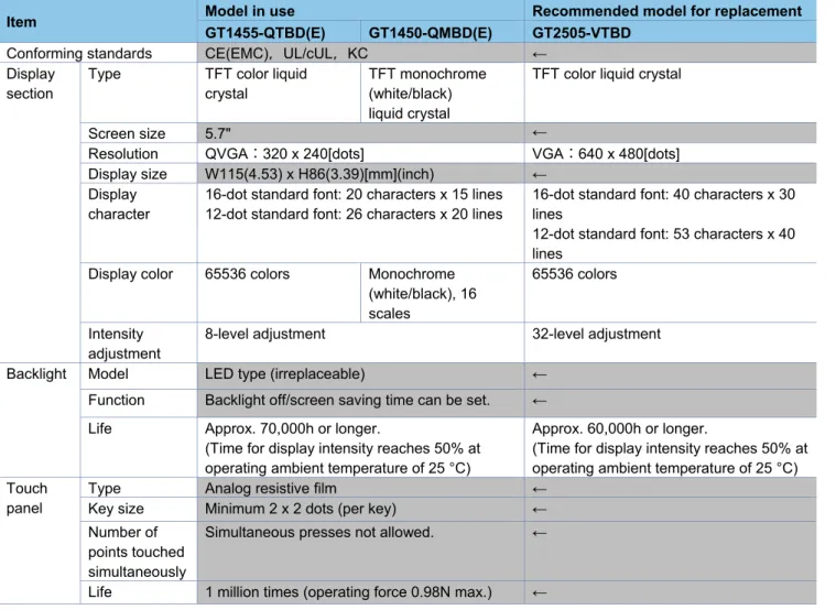
3.1.1
Performance comparison between the GT14 model and GT2505-VTBD
For cells filled in grey, the specifications remain even after replacement.
Table 3-1 Comparison in performance specifications
Item Model in use Recommended model for replacement
GT1455-QTBD(E) GT1450-QMBD(E) GT2505-VTBD
Conforming standards CE(EMC),UL/cUL,KC ← Display
section
Type TFT color liquid crystal
TFT monochrome (white/black) liquid crystal
TFT color liquid crystal
Screen size 5.7" ←
Resolution QVGA:320 x 240[dots] VGA:640 x 480[dots] Display size W115(4.53) x H86(3.39)[mm](inch) ←
Display character
16-dot standard font: 20 characters x 15 lines 12-dot standard font: 26 characters x 20 lines
16-dot standard font: 40 characters x 30 lines
12-dot standard font: 53 characters x 40 lines
Display color 65536 colors Monochrome (white/black), 16 scales
65536 colors
Intensity adjustment
8-level adjustment 32-level adjustment
Backlight Model LED type (irreplaceable) ←
Function Backlight off/screen saving time can be set. ←
Life Approx. 70,000h or longer.
(Time for display intensity reaches 50% at operating ambient temperature of 25 °C)
Approx. 60,000h or longer.
(Time for display intensity reaches 50% at operating ambient temperature of 25 °C) Touch
panel
Type Analog resistive film ←
Key size Minimum 2 x 2 dots (per key) ← Number of
points touched simultaneously
Simultaneous presses not allowed. ←
Item
GT1455-QTBD(E) GT1450-QMBD(E) GT2505-VTBD
Memory User memory Built-in flash memory, 9Mbytes
Life (Number of write times): 100,000 times
Memory for storage (ROM): 32MB Memory for operation (RAM): 80MB Life (Number of write times): 100,000 times
Built-in SRAM Drive D: 512KB SRAM user area: 500KB Battery Model GT11-50BAT lithium battery ←
Life Approx. 5 years (Operating ambient temperature of 25 °C)
←
Built-in interface
RS-422/ 485
Specific ations
1 channel, Connector shape: D-sub 9-pin (female)
←
RS-232
Specific ations
1 channel, Connector shape: D-sub 9-pin (male)
←
Ethernet GT1455-QTBDE, GT1450-QMBDE only 1 channel Data transfer method: 100BASE-TX, 10BASE-T,
Connector shape: RJ-45 (modular jack)
1 channel Data transfer method: 100BASE-TX, 10BASE-T,
Connector shape: RJ-45 (modular jack)
USB (host) 1 channels,Maximum transfer rate: Full Speed 12Mbps Connector shape: USB-A (rear face)
1 channels,Maximum transfer rate: High-Speed 480 Mbps Connector shape: USB-A (rear face)
USB (device) 1 channels,Maximum transfer rate: Full Speed 12Mbps Connector shape: Mini-B (front face)
1 channels,Maximum transfer rate: High-Speed 480 Mbps Connector shape: USB Mini-B (front face)
SD card 1 channel, SDHC compliant (maximum 32 GB) ←
Buzzer output Single tone (tone length adjustable) Single tone (tone and tone length adjustable)
POWER LED 2 colors (green and orange) 2 colors (blue and orange) Protective structure I IP67f (front section of the panel only) ←
External dimensions 164(6.46)(W) × H135(5.32)(H) ×55(2.17) (D) mm(inch)
164(6.46)(W) × 139(5.47)(H) × 53.5(2.11)(D) mm(inch) Panel cutting dimension 153(6.02)(W) × 121(4.76) (H) mm(inch) ←
Weight (Excluding mounting fixtures)
Approx. 0.7kg Approx. 0.6kg
Compatible software package
GT Designer3 Version1.34L or later
GT Designer3 Version1.118Y or later
GT Designer3 Version1.180N or later
Installing procedure Vertical or Horizontal ← Control Panel Inside
Dimensions for Mounting GOT
Refer to the following.
➟ 3.4 Installing the GOT
Refer to the following.
➟ 3.4 Installing the GOT
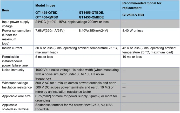
3.1.2
Comparison in power supply specifications between the GT14 model and GT2505-VTBD
For cells filled in grey, the specifications remain even after replacement.
Table 3-2 Comparison in power supply specifications
Item
Model in use Recommended model for
replacement
GT1455-QTBD,
GT1450-QMBD
GT1455-QTBDE,
GT1450-QMBDE GT2505-VTBD
Input power supply voltage
24VDC (+10% -15%), ripple voltage 200mV or less ←
Power consumption (Under the
maximum load)
7.68W(320mA/24V) 8.40W(350mA/24V) 8.40 W or less
Inrush current 30 A or less (2 ms, operating ambient temperature 25 °C, maximum load)
42 A or less (2 ms, operating ambient temperature 25 °C, maximum load) Permissible
instantaneous power failure time
5 ms or less 10 ms or less
Noise immunity 1000 Vp-p noise voltage, 1s noise width (when measuring with a noise simulator under 30 to 100 Hz noise
frequency)
←
Withstand voltage 500 V AC for 1 minute across power terminals and earth ← Insulation resistance 500 V DC across power terminals and earth, 10 MΩ or
more by an insulation resistance tester
←
Applicable wire size 0.75[mm2] or more for power supply, 2[mm2] or more for grounding
←
Applicable solderless terminal
Solderless terminal for M3 screw RAV1.25-3, V2-N3A, FV2-N3A
3.2 External dimension comparison
■GT14 model
■
GT2505-VTBD
1 3 5 (5 .3 2 ) 5 5 (2 .1 7 ) 4 7 (1 .8 6 ) 1 2 0 (4 .7 3 ) 1 0 (0 .4 ) (0 .2 4 ) 1 0 (0 .4 ) 164(6.46) 22 (0.87) (0.91) 120(4.73) 23 6 120(4.73) 152(5.99)Unit: mm (inch) 22 (0.87) 164(6.46) 1 2 0 (4 .7 2 ) 1 3 9 (5 .4 7 ) 1 0 (0 .3 9 ) 1 0 (0 .3 9 )
3.3 Panel cutting dimension comparison
■Horizontal installation
■Vertical installation
For cells filled in grey, the specifications remain even after replacement.
Item Model in use Recommended model for replacement
GT14 model GT2505-VTBD
A 153(6.02)
-0(0) +2(0.08)
mm (inch) ←
B 121(4.76)
-0(0) +2(0.08)
mm (inch) ←
C 10(0.39) mm (inch) or more ←
Panel thickness 2(0.08) to 4(0.16) mm (inch) 1.6(0.06) to 4(0.16) mm (inch)
A
B
C C
C
C
A
B
C
C
3.4 Mounting
intervals
■Horizontal installation
■Vertical installation
For cells filled in grey, the specifications remain even after replacement.
Item Model in use Recommended model for replacement
GT14 model GT2505-VTBD
A 50(1.97) or more [20(0.79) or more] mm (inch) ← B Horizontal: 80(3.15) or more [20(0.79) or more]
mm (inch)
Vertical: 50(1.97) or more [20(0.79) or more] mm (inch)
←
C Horizontal: 50(1.97) or more [20(0.79) or more] mm (inch)
Vertical: 80(3.15) or more [20(0.79) or more] mm (inch)
←
D 50(1.97) or more [20(0.79) or more] mm (inch) ←
E 100(3.94) or more [20(0.79) or more] mm (inch) ←
* The dimensions within the parentheses apply when no equipment generating radiated noise (such as a
contactor) or heat is installed near the GOT.
B
D E
A C
D
E A
3.5 Function
specifications
3.5.1 Comparison
in
functions
Most of the functions of the GOT1000 series can be used in the GOT2000 series; however, some functions are
not supported or are integrated, or their names have been changed. For the details, refer to "Table 3-3 GOT2000
function comparison table".
For each function of the GOT2000 series, refer to the manual.
(1) Functions not supported by the GOT2000 series
- Data list display
- A list editor
- Multiple GOT connection
(2) Integrated functions and functions with changed names
Function name in GOT1000 Function name in GOT2000
Basic comment Comment group
Comment group
Alarm history, alarm history display User alarm observation, alarm display (user) Advanced user alarm observation, advanced user alarm
display
Recipe Recipe Advanced recipe
Status observation function Trigger action Trigger action
ASCII display, ASCII input Text Display/Input
User alarm display Simple Alarm display
Advanced system alarm observation, advanced system alarm display
System alarm observation, alarm display (system)
Advanced alarm popup display Alarm Popup Display
System monitor Device monitor
(1) Detailed comparison in functions
The following tables shows the differences in the functions between the GOT1000 series and GOT2000 series.
Table 3-3 GOT2000 function comparison table
Item Function name in GOT1000 GT14 GT2505-V Precautions for replacing GOT1000 series with
GOT2000 series F ig u re /o b je ct fu n ct io n Sh a p e s
Shapes ● ● -
Logo Text ● ● -
F o n t t yp e
Standard Font ● ● [Precautions]
- Refer to Section 3.6.4(2)
HQ font ● ● -
TrueType font ● ● -
Stroke font ● ● [Precautions]
- Converted into Outline font (Outline Gothic).
Windows font ● ● -
C
o
mmo
n
Text ● ● -
Trigger type ● ● -
Offset device ● ● [Precautions]
- Refer to Section 3.6.4(2)
Number of colors ● ● -
Buffer memory unit No. switching ● ● - O b je ct
Touch switch ● ● [Precautions]
- The special function switches that GOT2000 does not support are replaced with [Utility].
- When multiple actions have been set on a switch and no device has been set to one of the actions in the [Action] tab, touching the switch may not perform actions after the action to which no device has been set.
Lamp ● ● [Precautions]
- The [Use Image Transparent] setting for when objects registered in the library are used will be deleted. Transparent color is effective in
GOT2000 regardless of the settings in GOT1000.
Numerical Display/Input ● ● -
ASCII display/input ● ● -
Date/Time Display ● ● -
Comment Display ● ● [Precautions]
- When [16dot HQ Mincho] or [16dot HQ Gothic] is specified for comment display (bit), the setting is replaced as follows.
- When the text size (width × height) is any of 0.5, 1, 3, 5, or 7:
The font selected in [16dot Standard Font] in the type setting of GOT1000.
2, 4, 6, or 8: [16dot HQ Mincho]
Basic comment ● ● [Precautions]
- Replaced with [Comment Group].
- [Basic Comment] is replaced with the comment group No. 256.
Comment group ●
●(Without version) : Supported by GT Works3 Ver1.180N or later
Item Function name in GOT1000 GT14 GT2505-V GOT2000 series F ig u re /o b je ct fu n ct io n O b je ct
Parts Display ● ● [Precautions]
- When [Fixed Parts Display] is used, [Rise] and [Fall] are replaced with [ON] and [OFF].
Parts movement ● ● -
Data list display ● × [Precautions]
- Not supported by GOT2000. User alarm display ● ● [Precautions]
- Replaced with [Simple Alarm Display]. - [Rise], [Fall], and [Sampling] of the trigger type
setting are replaced with [Ordinary].
- Text alignment of the comment setting (multiple rows) will be deleted. Text are aligned left in GOT2000 regardless of the setting of GOT1000. - [Store Memory] is not supported. When [Store
Memory] is used, replace it with [User Alarm Observation] or [Alarm Display(User)].
System Alarm Display ● ● -
Historical Data List Display ● ● - Alarm history, alarm history
display
● ● [Precautions]
- Replaced with [User Alarm Observation] or [Alarm Display(User)].
- Replaced with [Time (hh:mm)] when [Text] is set as the date/time format for [Occurred], [Restored], and [Checks] of the displayed items in [Alarm History Display].
- When [CREATE A CSV FILE
SIMULTANEOUSLY] is selected in [Alarm History], set the setting again in [Alarm Common Setting] of [User Alarm Observation] with GOT2000.
- GT2505-V cannot be saved in the drive D. Use the data storage since the drive D is replaced with the drive X. For the available drives, refer to Section 3.6.4 (3).
Advanced user alarm observation, advanced user alarm display
●
Advanced system alarm observation, advanced system alarm display
● ● [Precautions]
- Replaced with [System Alarm Observation] or [Alarm Display(System)].
- GT2505-V cannot be saved in the drive D. Use the data storage since the drive D is replaced with the drive X. For the available drives, refer to Section 3.6.4 (3).
Advanced alarm popup display
● ● [Precautions]
- Replaced with [Alarm Popup Display].
Level object ● ● -
Panel Meter ● ● [Precautions]
- [Top 1/4], [Bottom 1/4], [Left 1/4], and [Right 1/4] are replaced with [Top 1/6], [Bottom 1/6], [Left 1/6], and [Right 1/6] respectively. The display size is not changed.
Line Graph ● ● [Precautions]
- [Locus] is not supported.
Trend Graph ● ● [Precautions]
- Replaced with [Historical Trend Graph] or [Logging] when [Store Memory] is set. However, this function will be deleted when the number of logging settings exceeds the upper limits.
●(Without version) : Supported by GT Works3 Ver1.180N or later
Item Function name in GOT1000 GT14 GT2505-V GOT2000 series F ig u re /o b je c t f u n c tio n O b je ct
Bar Graph ● ● -
Statistics Bar Graph ● ● -
Statistics per screen ● ● -
Scatter Graph ● ● -
Historical Trend Graph ● ● -
Key Window Object ● ● -
F u n ct io n s p e rf o rme d o n b a ck g ro u n d
Logging ● ● -
Recipe ● ● [Precautions]
- Replaced with [Recipe], which is equivalent to the advanced recipe of GOT1000.
- The number of advanced recipe of GOT1000 is replaced with those with the same recipe number in GOT2000.
- The recipe number used in GOT1000 is replaced with the recipe number after the advanced recipe number used in GOT1000.
- The following function is not supported.
- Creating a recipe file automatically if no recipe file is found at startup
- Specifying the file register name
- The format of recipe file (CSV/Unicode text) is different. When using a recipe file of GOT1000 in GOT2000, change the format into the one for GOT2000. For the details, refer to Section 3.2.2(2).
- GT2505-V cannot be saved in the drive D. Use the data storage since the drive D is replaced with the drive X. For the available drives, refer to Section 3.6.4 (3).
Advanced recipe ●
Device data transfer ● ● -
Status observation function ● ● [Precautions]
- Replaced with [Trigger Action].
- Because the trigger action has no [Observation Cycle] setting, the setting is replaced with one of [ON Sampling], [OFF Sampling], and [Ordinary] in the [Trigger Type] setting when the [Observation Cycle] setting has been set. Thus, the action timing in the first cycle may change.
Trigger action ●
Time action ● ● [Precautions]
- GT2505-V cannot be saved in the drive D. Use the data storage since the drive D is replaced with the drive X. For the available drives, refer to Section 3.6.4 (3).
Hard copy (File output)
● ● [Precautions]
- The setting of the trigger watch cycle will be deleted. The trigger watch cycle is set to [Ordinary] regardless of the setting in GOT1000. - GT2505-V cannot be saved in the drive D. Use
the data storage since the drive D is replaced with the drive X. For the available drives, refer to Section 3.6.4 (3).
Hard copy
(Serial printer output)
● ● [Precautions]
- The setting of the trigger watch cycle will be deleted. The trigger watch cycle is set to [Ordinary] regardless of the setting in GOT1000.
●(Without version) : Supported by GT Works3 Ver1.180N or later
Item Function name in GOT1000 GT14 GT2505-V GOT2000 series F u n ct io n s p e rf o rme d o n b a ck g ro u n d
Project/screen script ● ● [Precautions]
- The setting of [Cancel internal device (GD/GB) assignment delay] will be deleted. In GOT2000, the result of assignment of internal devices (GD/GB) is reflected immediately regardless of the setting in GOT1000
- [Perform script initial operation (screen/object) only when switching screens] is added to
GOT2000. The setting will be replaced as follows. When using GT Designer3 Version1.103H or earlier:
Checked
When using GT Designer3 Version1.105K or later:
Not checked (compatible with GOT1000) - The trigger type of a script is replaced as shown
below.
[Ordinary] → [Sampling] (Cycle time: 100 ms)
[ON] → [ON Sampling] (Cycle time: 100 ms)
[OFF] → [OFF Sampling] (Cycle time: 100 ms) - When the drive D is specified with the file
operation function, change the designated location of the drive. For the available drives, refer to Section 3.6.4 (3).
Object Script ● ● [Precautions]
- [Perform script initial operation (screen/object) only when switching screens] is added to
GOT2000. The setting will be replaced as follows. When using GT Designer3 Version1.103H or earlier:
Checked
When using GT Designer3 Version1.105K or later: Not checked (compatible with GOT1000)
F U N C T IO N S U SED W IT H PER IPH ER AL D EVI C ES
Barcode ● ● -
RFID ● ● -
GOT remote access function (VNC server function)
● ● [Precautions]
- Purchase separately since the license is different. Report function
(Serial printer output) ● ●
-
Gateway function (Server function, client function)
● ● -
Gateway function (Mail send function)
● ● -
Gateway function (FTP server function)
● ● [Precautions]
- GT2505-V cannot be saved in the drive D. For the available drives, refer to Section 3.6.4 (3). Gateway function
(File transfer (FTP client) function)
● ● [Precautions]
- The save location is switched to the drive A. For the available drives, refer to Section 3.6.4 (3).
●(Without version) : Supported by GT Works3 Ver1.180N or later
Item Function name in GOT1000 GT14 GT2505-V GOT2000 series
G
O
T
fu
n
ct
io
n
Base screen ● ● -
Overlap window ● ● -
Superimpose window ● ● -
Dialog window ● ● -
Key window ● ● -
Language Switching ● ● -
System information ● ● -
Operator authentication ● ● -
Security level authentication ● ● -
Startup Logo ● ● -
KANA-KANJI Conversion ● ● -
FA transparent ● ● [Precautions]
- Modem connection and RS-232 connection between the GOT and a personal computer are not supported.
Backup/Restore ● ● [Precautions]
- GT Refer to Section 3.3.4(6).
Multi-channel function ● ● -
Station No. Switching ● ● -
D
e
b
u
g
fu
n
ct
io
n
System monitor ● ● [Precautions]
- Replaced with [Device monitor].
- The display method for device comments is the same as the one for the sequence program monitor.
A list editor ● × [Precautions]
- Not supported by GOT2000.
- The special function switch [MELSEC-A LIST EDITOR] is replaced with [Utility].
List editor for FX ● ● -
MELSEC-L troubleshooting ● ● - Maintenance report ● × [Precautions]
- Not supported by GOT2000.
- The special function switch [Maintenance Report] is replaced with [Utility].
(2) Recipe files (CSV/Unicode text) of the recipe and advanced recipe
The format of the recipe files (CSV/Unicode text) differs between the GOT1000 series and GOT2000 series.
When using a recipe file (CSV/Unicode text) for the GOT1000 series in the GOT2000 series, change the format
into the one for the GOT2000 series.
●(Without version) : Supported by GT Works3 Ver1.180N or later
1) For the recipe
(a) Convert the project data into the GOT2000 series project data, and execute the recipe.
(b) A recipe file for the GOT2000 series (CSV/Unicode text) is created in the specified drive.
(c) Copy the device values in the recipe file for the GOT1000 series onto the corresponding section in the
recipe file for the GOT2000 series.
- GOT1000 recipe file
:DATE
2014/1/31 12:38
PM
:GROUP No.
1
:GROUP NAME
RECIPE1
:DEVICE 8
ITEM NAME
VALUE
234
421
52
-23
534
-3
32
0
- GOT2000 recipe file (number of records: 1)
:GT2K_RECIPE 0
:RECIPE_ID 1
:RECIPE_NAME RECIPE1
:DEVICE_NUM 8
:RECORD_NUM 1
:DATE_ORDER
YYYY/MM/DD
hh:mm:ss
:LOCAL_TIME GMT+09:00
:TIME_INF_ORDER L
DEV_COMMENT
DEV_TYPE DISP_TYPE DEV_SIZE
1
:RECORD_NAME
:RECORD_ATTR
:UPDATE
2014/1/31 12:38
PM
1
BIN16 DEC
234
2
BIN16
DEC
1
421
3
BIN16
DEC
1
52
4
BIN16
DEC
1
-23
5
BIN16
DEC
1
534
6
BIN16
DEC
1
-3
7
BIN16
DEC
1
32
8
BIN16
DEC
1
0
(a) Convert the project data into the GOT2000 series project data, and execute the recipe.
(b) A recipe file for the GOT2000 series (CSV/Unicode text) is created in the specified drive.
(c) Copy the device values in the recipe file for the GOT1000 series onto the corresponding section in the
recipe file for the GOT2000 series.
(d) When using the file in the GOT, convert the file format from CSV/Unicode text to binary in either of the
following procedure.
- Utility of the GOT - GT Designer3 (GOT2000) - Data Transfer Tool
- GOT1000 advanced recipe file (number of records: 2)
:ARECIPE
:ARECIPE_No 1
:ARECIPE_NAME RECIPE1
:DEVICE_NUM 8
:RECORD_NUM 2
DEV_COMMENT DEV_TYPE DISP_TYPE DEV_SIZE 1 2
:RECORD_NAME PRO1 PRO2
:RECORD_ATTR P
:UPDATE
2014/1/31 10:30:15
2014/1/31 10:30:15
1 STD A BIN16 DEC 2 454 400
2 CNT1 BIN16 UNSIGNED_DEC 2 10000 40000
3 LINE A BIN16 DEC 2 10000 40000
4 LINE B BIN16 DEC 2 10000 40000
5 LINE C BIN16 DEC 2 10000 40000
6 CNT2 BIN32 DEC 4 120000000 200000000
7 TARGET1 BIN32 DEC 4 100000000 500000000
8 TARGET2 BIN32 UNSIGNED_DEC 4 200000000 600000000
- GOT2000 recipe file
:GT2K_RECIPE 0
:RECIPE_ID 1 :RECIPE_NAME RECIPE1
:DEVICE_NUM 8
:RECORD_NUM 2
:DATE_ORDER
YYYY/MM/DD hh:mm:ss
:LOCAL_TIME GMT+09:00
:TIME_INF_ORD
ER L
DEV_COMMENT DEV_TYPE DISP_TYPE DEV_SIZE 1 2
:RECORD_NAME PRO1 PRO2
:RECORD_ATTR P
:UPDATE
2014/1/31 10:30:15
2014/1/31 10:30:15
1 STD A BIN16 DEC 1 454 400
2 CNT1 BIN16 UNSIGNED_DEC 1 10000 40000
3 LINE A BIN16 DEC 1 10000 40000
4 LINE B BIN16 DEC 1 10000 40000
5 LINE C BIN16 DEC 1 10000 40000
6 CNT2 BIN32 DEC 2 120000000 200000000
7 TARGET1 BIN32 DEC 2 100000000 500000000
8 TARGET2 BIN32 UNSIGNED_DEC 2 200000000 600000000
The project data used in the GOT1000 series can be converted into the project data for the GOT2000 series, and
can be used as-is.
[Precautions]
This explanation is based on GT Works3 Version1.180N.
Once the project data is converted for the GOT2000 series, it cannot be converted back into the project data for
the GOT1000 series.
3.6.1
Preparation before converting the project data
Install the following software into the personal computer in advance.
(1) When reading the project data for the GOT1000 series from a GOT
Install GT Designer3 (GOT1000) (GT Works3 Version1.180N or later) or Data Transfer Tool.
* Not necessary if any project data already exists in the personal computer.
(2) When converting the project data for the GOT2000 series
Install GT Designer3 (GOT2000) (GT Works3 Version1.180N or later).
For how to install the software, refer to the following.
- GT Works3 Installation Instructions (DVD version) (BCN-P5999-0066)
3.6.2
Procedure for the project data conversion
1) When the data exists on the personal computer, check the storage location of the project data for the
GOT1000 series.
When no data exists on the personal computer, connect the personal computer to the GOT1000 series, and
read and save the project data using GT Designer3 (GOT1000) or Data Transfer Tool.
2) Open the project data of procedure 1) with GT Designer3 (GOT2000), and select [Convert the project to
GOT2000 data and edit it in GT Designer3 (GOT2000)].
Setting], select [GOT2000] in [Series] of [GOT Type], and press [OK].
3) Select the model of GOT2000 after replacement, and press [OK].
The following screen design functions are not supported.
Item Screen design
function GT14 GT2505-V
Precautions for GOT1000-to-GOT2000 replacement
Screen design software
Communication between the screen design software and GOT (modem, RS-232)
● × [Precautions]
Modem or RS-232 connection between the screen design software and GOT is not supported. Use USB or Ethernet connection.
[Precautions]
Note that the settings of the functions that are not supported in the GOT2000 series are deleted when the
GOT1000 series project data is converted for the GOT2000 series. For compatibility of the functions between the
GOT2000 series and GOT1000 series, refer to Section 3.2.
3.6.4
Other major changes
Major changes in the screen design function are as follows.
(1) Name of the OS (standard monitor OS, extended function OS)
The name is changed as follows. In the GOT2000 series, the data necessary for GOT operations including
system applications, project data, and communication drivers are collectively called "package data".
Name in GOT1000 Name in GOT2000
OS System application
Standard monitor OS Standard system application Extended function OS Advanced system application
(2) Name of standard fonts
The name and type of the standard fonts are changed as follows.
Name in GOT1000 Precautions and names changed in GOT1000-to-GOT2000 replacement
Japanese *1 Japanese *3
* Replaced to a font equivalent to Japanese (supporting Europe) of the GOT1000 series.
Japanese (supporting Europe) *2 Japanese *3
Chinese (Simplified) *1 Chinese (Simplified) *3
* Replaced to a font equivalent to Chinese (Simplified) (supporting Europe) of the GOT1000 series.
Chinese (Simplified) (supporting Europe) *2 Chinese (Simplified) *3 Chinese (Traditional) (supporting European) *2 Chinese (Traditional) *3
*1 European characters (Latin-1 Supplement, Latin Extended-A, Basic Greek, and Cyrillic) are displayed in two-byte characters. *2 European characters (Latin-1 Supplement, Latin Extended-A, Basic Greek, and some of Cyrillic) are displayed in one-byte
characters.
The name and type (media) of drives are different as follows.
Drive name Drive type
GT14 GT2505-V
Drive A Standard CF card Standard SD card Drive C Built-in flash memory Built-in flash memory
Drive D Built-in SRAM -
Drive E USB USB (assigned in order of connection) Drive F - USB (assigned in order of connection) Drive G - USB (assigned in order of connection) Drive X
(Current drive)
- A drive that is running a project.
(Indicates A drive when the project is started from C drive.)
(4) Storage locations of data
The storage locations of data are different as follows.
Data type Storage drive
GT14 GT2505-V
OS A, C drive Pa
cka
g
e
d
a
ta
A, C, E, F, G drive * Project data and system application must be stored in the same drive.
* Only A drive can be used for direct startup from a memory card. Project data A, C drive
* Only A drive can be used when the OS is stored in A drive.
Resource data A, D, E drive
* Storage locations differ depending on the type.
(5) GOT setup settings (backup/restore)
Setting categories in the screen design software for the GOT2000 series differ. Depending on the settings, those
in GOT1000 may be deleted. Check and set them again in the screen design software for the GOT2000 series if
necessary.
Setting categories in the screen design software for the GOT1000 series "GT Designer3 (GOT1000)"
[Common]-[Environmental Setting]-[GOT Setup]
Setting categories in the screen design software for the GOT2000 series "GT Designer3 (GOT2000)"
[Common]-[GOT Setup]-[Advanced Setting]
When offsets are used and the following conditions are satisfied, the values stored in the offset devices must be
changed.
1) Conditions requiring changes
• Controller: OMRON PLC
• Connection type: Serial connection or Ethernet connection
• Offset-target device: Bit devices (.., LR, HR, WR, and AR)
2) Change method
Values stored in the offset devices can be calculated using the following expression. Store the result in the
offset devices.
Offset value for the GOT2000 series = (Offset value for the GOT-A900 series) / 100 × 16
+ (Offset value for the GOT-A900 series) % 100
* % means the division to calculate a remainder. (For "a % b", a remainder after "a" is divided by "b" is
returned.)
Example) The following shows an example of offset values for the device LR00000.
Object setting in the GOT Device number after the offset is added Offset value for the GOT-A900 series (decimal)
Offset value for the GOT2000 series
(decimal) (calculated by the expression)
LR00000 LR00010 10 10
LR00100 100 16
LR00310 310 58
LR010000 10000 1600
3) Difference in the specifications of the offsets of bit devices (.., LR, HR, WR, and AR)
In the GOT1000 series, values must be set corresponding to the device notation (channel number and bit
position). In the GOT2000 series, values disregarding channel numbers are set while bit devices are
considered continuous.
Example) The following shows an example for the GOT1000 series.
Offset Device indicated by the monitor device
Offset value = 0 (no offset) LR00000
Offset value = 1 LR00001
Offset value = 15 LR00015
Offset value = 16 322 (range error)
Offset value = 100 LR00100
Offset value = 115 LR00115
*1 The notation of bit devices is as follows (example of LR):
LR
□□□
ᇞᇞ
*2 The lower two digits of the offset value are applied as an offset value for the bit position in *1. The valid value
is 0 to 15. If 16 to 99 is set, the system alarm 322 "Dedicated device is out of range. Confirm device range."
is displayed.
The digits excluding the lower two digits of the offset value are applied as an offset value for the channel
number.
Offset Device indicated by the monitor device Offset value = 0 (no offset) LR00000
Offset value = 1 LR00001
Offset value = 15 LR00015
Offset value = 16 LR00100
Offset value = 100 LR00604
Offset value = 115 LR00703