高性能遅延蛍光材料の設計と有機発光ダイオードへ の応用
朴, 仁燮
https://doi.org/10.15017/1806987
出版情報:Kyushu University, 2016, 博士(工学), 課程博士 バージョン:
権利関係:Fulltext available.
2017
Doctoral Dissertation
Design of High-Performance Delayed Fluorescence Materials and
Their Application in Organic Light-Emitting Diodes
In Seob Park
Department of Chemistry and Biochemistry Graduate School of Engineering
Kyushu University
Table of Contents
Chapter 1. General Introduction
1. 1. Introduction……….2
1. 2. Photophysical Processes of Organic Materials…….………….………..3
1. 2. 1. Intramolecular Processes……….3
1. 2. 2. Intermolecular Processes……….6
1. 2. 2. 1. Long-Range Energy Transfer (Förster Energy Transfer)……….6
1. 2. 2. 2. Short-Range Energy Transfer (Dexter Energy Transfer)……….7
1. 2. 2. 3. Energy Transfer in Host–Guest System………8
1. 3. Thermally Activated Delayed Fluorescence (TADF) Process……….9
1. 3. 1. Design Principle for TADF Molecules………9
1. 3. 2. Determination of Rate Constants for TADF………..10
1. 3. 3. Efficiency of TADF-Based OLEDs………12
1. 4. Efficiency Roll-Off in OLEDs………...12
1. 5. Motivation and Outline of This Dissertation……….14
References……….16
Chapter 2. Wedge-Shaped Delayed Fluorescence Materials Based on Phthalonitriles and Dicyanopyrazines for Full-Color Electroluminescence 2. 1. Introduction………...21
2. 2. Molecular Geometric and Electronic Structures………21
2. 3. Photophysical Properties………....23
2. 4. Electroluminescence Performance……….28
2. 5. Experimental Section……….31
2. 5. 1 General Methods……….31
2. 5. 2. Preparation of Materials……….32
2. 5. 3. Synthesis………32
2. 5. 4. Device Fabrication and Measurements……….…….38
2. 6. Conclusion……….………38
References……….39
Chapter 3. Twisted Donor−Acceptor−Donor Delayed Fluorescence Materials Based on Pyrimidine for High-Performance Blue Organic Light-Emitting Diodes
3. 1. Introduction………...42
3. 2. Molecular Geometric and Electronic Structures………43
3. 3. Photophysical Properties………43
3. 4. Electroluminescence Performance……….47
3. 5. Experimental Section………...50
3. 5. 1. General Methods………50
3. 5. 2. Preparation of Materials……….50
3. 5. 3. Synthesis………51
3. 5. 4. OLED Fabrication and Measurements………...54
3. 6. Conclusion……….54
References……….55
Chapter 4. Twisted Donor−Acceptor Delayed Fluorescence Materials Based on Pyrimidine for Highly Efficient Blue Electroluminescence 4. 1. Introduction………...58
4. 2. Molecular Design………...59
4. 3. Photophysical and TADF Properties………..62
4. 4. Electroluminescence Performance……….66
4. 5. Experimental Section……….69
4. 5. 1. Materials………69
4. 5. 2. Synthesis………70
4. 5. 3. Quantum Chemical Calculations………..……….…………75
4. 5. 4. Photophysical Measurements………75
4. 5. 5. OLED Fabrication and Characterization………...76
4. 6. Conclusions………...76
References……….77
Chapter 5. A High-Efficiency Blue Delayed Fluorescence Material Based on Phenazaborin 5. 1. Introduction………...80
5. 2. Molecular Geometric and Electronic Structures………81
5. 3. Photophyscial Properties………82
5. 4. Electroluminescence Performance………....84
5. 5. Experimental Section………....86
5. 5. 1. General Methods………86
5. 5. 2. Preparation of Materials………....87
5. 5. 3. Synthesis………87
5. 5. 4. OLED Fabrication and Measurements………..90
5. 6. Conclusion………....91
References………....92
Chapter 6. Linear-Shaped Delayed Fluorescence Materials Based on Terephthalonitrile with Horizontally Oriented Dipoles for High-Efficiency Electroluminescence 6. 1. Introduction………...95
6. 2. Molecular Design and Quantum Chemical Calculations………..96
6. 3. Photophysical Properties………98
6. 4. Electroluminescence Properties………...102
6. 5. Molecular Orientation………..104
6. 6. Experimental Section………...106
6. 6. 1. General Methods………..106
6. 6. 2. Synthesis………..107
6. 6. 3. Photoluminescence Measurements………..111
6. 6. 4. OLED Device Fabrication and Measurements……….112
6. 7. Conclusion………...113
References………...114
Chapter 7. Cyclohexane-Coupled Bipolar Host Materials with High Triplet Energies for Organic Light-Emitting Diodes Based on Delayed Fluorescence 7. 1. Introduction……….117
7. 2 Molecular Geometric and Electronic Structures………..119
7. 3. Thermal and Photophysical Properties……….119
7. 4. Electroluminescence Performance………...123
7. 5. Experimental Section………...126
7. 5. 1. General Methods……….…….126
7. 5. 2. Materials and Synthesis………126
7. 5. 3. OLED Fabrication and Measurements……….131
7. 6. Conclusions……….132
References………...133
Chapter 8. Summary and Perspective……….….135
List of Publications………139
List of Symposium……….141
Acknowledgments……….142
1
Chapter 1
General Introduction
2 1. 1. Introduction
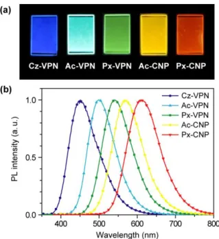
Organic light-emitting diodes (OLEDs) have attracted a great deal of attention, interest in their practical applications for full-color, flat-panel displays and lighting owing to virtue of their unique advantages such as the high electroluminescence (EL) efficiency, high contrast, light weight, flexibility, and potentially low manufacturing cost.
[1]In OLEDs, electrically injected holes and electrons are recombined to form 25% singlet excitons (antiparallel spins,
↑↓) and 75% triplet excitons (parallel spins, ↑↑), according to spin statistics.
[2]As shown in Figure 1-1, the operation of OLEDs involves charge injection from the electrodes, transport of charge carriers, and recombination of holes and electrons as the excitons under electrical- excitation, resulting in the emission of either fluorescence or phosphorescence in accordance with different radiative decay processes.
Figure 1-1. Schematic energy-diagram of OLEDs.
The first electroluminescence (EL) in an organic material was reported from an
anthracene single crystal by recombination of electrons and holes in 1965 by Helfrich and
Schneider.
[3]This discovery was not thought to be useful because rather high driving voltages
are necessary for light emission from the single crystal. After that, Tang and VanSlyke
demonstrated the first efficient organic light-emitting diode (OLED) based on tris(8-
hydroxyquinolinato)aluminum (Alq
3, Figure 1-2) with a luminance of over 1000 cd m
–2at a
voltage of 10 V and an external EL quantum efficiency (
ext) of nearly 1% utilizing an organic
multilayer structure in 1987.
[4]In 1990, Friend and coworkers exhibited the first polymer OLED
based on poly(p-phenylene vinylene) (PPV, Figure 1-2).
[5]Since these seminal reports have
been truly spectacular, the developments for highly efficient OLEDs have been conducted in
countless organic materials and device architectures.
[6]3
Figure 1-2. Molecular structures of tris(8-hydroxyquinolinato)aluminum (Alq
3, left) and poly(p-phenylene vinylene) (PPV, right).
1. 2. Photophysical Processes of Organic Materials
Excited organic molecules by photo- or electrical-excitation return to their original ground states with undergoing various deactivation processes (Figure 1-3).
Figure 1-3. Possible physical deactivation processes of excited organic molecules.
1. 2. 1. Intramolecular Processes
The electronic energy levels and electronic transitions of organic molecules can be shown using a Jablonski energy level diagram (Figure 1-4), which is convenient for visualizing in a simple way the possible deactivation processes. When a molecule has excited by photon absorption, the transition from its ground state (S
0) to a lowest excited singlet state (S
1) or higher excited singlet states (S
2–S
n) occurs with transient time of 10
–13to 10
–15s. As shown Figure 1- 4, the electron transfers from lowest vibrational level of S
0to the third vibrational level of the second excited singlet level (S
2) and causes the electron-collision of excited molecules with surrounding molecules. The electron then degrades to the lowest vibrational level of the same electronic energy level because of vibration energy loss. This process is known as vibrational relaxation (vr). Another degradation to the lowest vibrational level of a lower electronic energy level is called internal conversion (IC). These processes are so fast (10
–13to 10
–14s) that after molecules have excited by photon absorption, so they almost all instantly jump and down to the lowest vibration level of S
1. Subsequently, the following processes can occur:
Deactivation processes of excited states
Intramolecular processes
Radiative transitions
Fluorescence Phosphorescence Delayed
fluorescence
Non-radiative transitions
Internal conversion
Intersystem crossing
Intermolecular processes
Energy transfer Electron transfer
4
i) fluorescence: fluorescence is light emission of photons corresponding S
1→ S
0relaxation with transition time ranging from 10
–5to 10
–9s.
ii) intersystem crossing (ISC): ISC is the non-radiative transition from the excited singlet state to the excited triplet state. This process is slower (10
–8to 10
–10) than the IC process because of accompanying a spin transition.
iii) phosphorescence: phosphorescence is the radiative transition from the T
1to the S
0states with a change in spin direction with transition time ranging from 10 to 10
–6s.
iv) reverse intersystem crossing (RISC): RISC is a non-radiative transition from the excited to singlet states, which can occur when molecules possessing a small energy difference (ΔE
ST) between the excited singlet and triplet states.
v) delayed fluorescence: delayed fluorescence is the radiative transition from the S
1to S
0states involving the ISC and RISC processes. This process displays the same spectral distribution with conventional fluorescence. However, its decay time is longer than that of conventional fluorescence because a molecule emits as light emission after accompanying the ISC and RISC processes.
Figure 1-4. Jabloski energy level diagram. Vibrational relaxation (vr), internal conversion (IC), intersystem crossing (ISC), and reverse ISC (RISC) are non-radiative processes and fluorescence (lowest excited singlet state (S
1) → ground state (S
0)), delayed fluorescence (S
1→ lowest excited triplet state (T
1) → S
1→ S
0), and phosphorescence (T
1→ S
0) are radiative processes.
As shown in Figure 1-5, organic molecules show difference luminescence processes by excitation sources. Under the photo-excitation, nearly 100% excited singlet energies of organic
S2
T1
= 0
= 4
S0
= 0
= 4
S1 IC
ISC vr
Fluorescence or
delayed fluorescence Phosphorescence vr
vr
Absorption
Energy
RISC
5
molecules are generated, and then occur various transition processes as mentioned earlier. On the contrary, under electrical-excitation, singlet and triplet excitons are formed by recombination of electrons and holes, each of them carrying spin 1/2. The probability of forming a triplet exciton is statistically three times higher than that of forming a singlet exciton.
Therefore, internal EL quantum efficiencies (η
int) are believed to have a value of 25% for conventional fluorescence-based OLEDs as only the S
1excitons can be utilized for light emission (Figure 1-6a).
[7]In this case, the T
1excitons undergo a spin-forbidden transition, resulting in non-radiative deactivation. But in contrary to this, precious metal-containing organometallic phosphorescent materials are capable of harvesting both S
1and T
1excitons for light emission (Figure 1-6b).
[2]this is because of the enhanced ISC mediated by a spin–orbit coupling of the heavy metals such as iridium (Ir), platinum (Pt), and osmium (Os), which results in
intof up to 100%.
[8]Despite their desirable EL characteristics, the rarity, high cost, and toxicity of these precious metals, as well as the poor stability of blue phosphors would hamper the widespread applications of these OLEDs in the future. As an alternative, thermally activated delayed fluorescence (TADF, Figure 1-6c), which occurs by converting the excited T
1states to emissive S
1states via an efficient RISC using purely organic emitters without any precious metal elements, has attracted great attention in recent years.
[9–14]Owing to efficient up- conversion from the T
1to S
1states, highly efficient TADF-OLEDs with
intof nearly 100%
have been successfully realized,
[9a]and hence TADF is expected as a key technology for the next-generation OLEDs.
Figure 1-5. Schematic representation for PL (left) and EL (right) decay processes. k
nSand k
nrSare the radiative and non-radiative decay rate constants of S
1, respectively. k
nTand k
nrTare the
radiative and non-radiative decay rate constants of T
1, respectively. k
ISCand k
RISCare the non-
radiative decay rate constants of ISC and RISC, respectively.
6
Figure 1-6. Schematic representation for (a) fluorescence, (b) phosphorescence, and (c) TADF mechanisms under electrical-excitation. η
intis the internal EL quantum efficiency.
1. 2. 2. Intermolecular Processes
1. 2. 2. 1. Long-Range Energy Transfer (Förster Energy Transfer)
Förster energy transfer is long-range dipole–dipole (Coulombic) energy transfer in the range of up to 10 nm, which is a consequence of electron–electron repulsions of a donor molecule (D) and an acceptor molecule (A).
[15]Energy transfer occurs from the excited state of a donor molecule (D*) to the S
0state of an acceptor molecule (A), according to D* + A → D + A* (Figure 1-7). There are physical parameters to occur the efficient energy transfer as follows, i) there should be the good spectral overlap between the emission spectrum of the donor and the absorption spectrum of the acceptor and ii) the relative orientation between the emission dipole moment of the donor and the absorption dipole moment of the acceptor. This energy transfer is only allowed singlet–singlet energy transfer (
1D* +
1A →
1D +
1A*) between the donor and acceptor without a change in spin multiplicity, resulting in the creation of significant transition dipoles, whereas triplet–triplet energy transfer (
3D* +
1A →
1D +
3A*) cannot occur because this is required to a change in spin multiplicity.
The efficiency of the Förster energy transfer process depends on the increase sixth power of the distance between the donor and acceptor pair (r) given by following equation:
𝐸
F= 𝑅
06/(𝑅
06+ 𝑟
6) (1-1)
where R
0is Förster radius at which the efficiency of energy transfer is 50%, which can be
determined from photophysical data by employing following equation:
7 𝑅
06=
9(ln10)𝜅2𝛷D128𝜋5𝑁𝐴𝑛4
𝐽 (1-2)
where κ
2is the dipole orientation factor, Φ
Dis the PL quantum efficiency of the donor in the absence of transfer, N
Ais the Avogadro’s number, n is the refractive index of the medium, and J is the spectral overlap integral calculated as
𝐽 = ∫ 𝑓
D(𝜆)𝜀
A(𝜆)𝑑𝜆 (1-3)
where f
Dis normalized emission spectrum of the donor and ε
Ais molar extinction coefficient from the absorption spectrum of the acceptor.
Figure 1-7. Schematic representation for (a) singlet–singlet Förster energy transfer, (b) singlet–singlet Dexter energy transfer, and (c) triplet–triplet Dexter energy transfer.
1. 2. 2. 2. Short-Range Energy Transfer (Dexter Energy Transfer)
Dexter energy transfer is short-range energy transfer by an emission quenching mechanism in which an excited electron of the donor is transferred to that of the acceptor through a non-radiative path at short distances (~ 1 nm) of the donor and acceptor. This process
HOMO LUMO
1D* + 1A 1D + 1A*
(a) Singlet–singlet Förster energy transfer
HOMO LUMO
1D* + 1A 1D + 1A*
(b) Singlet–singlet Dexter energy transfer
HOMO LUMO
3D* + 1A 1D + 3A*
(c) Triplet–triplet Dexter energy transfer
8
is allowed both singlet–singlet (
1D* +
1A →
1D +
1A*) and triplet–triplet (
3D* +
1A →
1D +
3
A*) energy transfer (Figure 1-7).
[16]Therefore, the wavefunction overlap between the donor and acceptor is required for efficient Dexter energy transfer. The rate constant of Dexter energy transfer is given by following equation:
𝑘
𝐷= (
2𝜋ℎ
) 𝜅
2exp(
−2𝑅DA𝐿
)𝐽 (1-4)
where R
DAis the distance between the donor and acceptor, L is the sum of the Van der Waals radii of the donor and acceptor, and J is the spectral overlap integral calculated as the eqn. 1-3.
Figure 1-8. Schematic representation for energy transfer between a host material and a TADF emitter under electrical-excitation. S
0Hand S
0Eare the ground states, S
1Hand S
1Eare the lowest excited singlet states, and T
1Hand T
1Eare the lowest excited triplet states of the host and TADF materials, respectively.
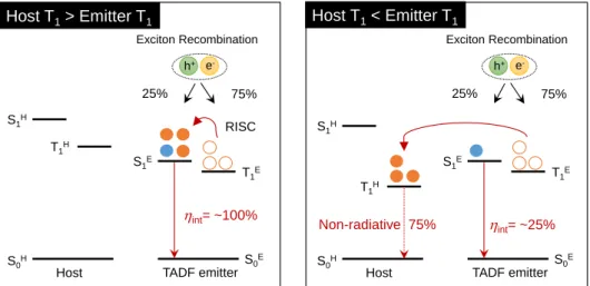
1. 2. 2. 3. Energy Transfer in Host–Guest System
Emitting materials have to be dispersed into a suitable host matrix at a low concentration (1–10 wt.%) to reduce concentration quenching and avoid self-absorption of emitting materials in OLEDs to realize the high EL efficiency.
[17]In addition, triplet harvesting emitters (phosphorescent and TADF materials) should be required to employ a host material with high triplet energy (E
T) to prevent backward energy transfer from the triplet state of the emitter to that of the host material, because both Förster and Dexter energy transfer occur in phosphorescence and TADF molecules in a host matrix. As exemplified Figure 1-8, 75% triplet excitons of a TADF emitter transferred to the triplet state of a host material, and hence dissipated as the non-radiative process when using a host material with a lower triplet state than that of a TADF emitter. Therefore, it is important to select suitable host materials for the high
h+ e-
S1H
S0H S0E
S1E T1H
T1E 25%
Exciton Recombination
75%
Host TADF emitter
RISC
int= ~100%
h+ e-
S1H
S0H S0E
S1E T1H
T1E 25%
Exciton Recombination
75%
Host TADF emitter
int= ~25%
Non-radiative 75%
Host T1> Emitter T1 Host T1< Emitter T1
9
EL efficiency in OLEDs. Design of highly efficient host materials for TADF emitters will be discussed in Chapter 8.
1. 3. Thermally Activated Delayed Fluorescence (TADF) Process 1. 3. 1. Design Principle for TADF Molecules
The efficient TADF emission is usually observed organic materials with a small ΔE
ST(k
BT ≈ 25.6 meV) because the RISC process can be strongly accelerated by the thermal energy at 300 K, in accordance with Fermi’s Golden rule, in which k
RISCis expressed by the following equation:
[18]𝑘
RISC=
2𝜋ℏ
< 𝛹
1|𝐻
𝑆𝑂|𝛹
2>
2 1√4𝜋𝜆𝑘B𝑇
𝑒𝑥𝑝 (−
(Δ𝐸ST+𝜆)24𝜋𝜆𝑘B𝑇
) (1-5)
where, ℏ and H
SOare the Planck constant and spin–orbit coupling between two states (𝛹
1→ 𝛹
2), respectively. and k
Bare the mixing coefficient between two states (𝛹
1→ 𝛹
2) and the Boltzmann constant, respectively. T is the absolute temperature. The RISC process in purely organic materials with a negligible small H
SOcan be accelerated by realizing a small ΔE
ST, which is due entirely to electron–electron repulsions. Generally, electron–electron repulsion energies are distributed as two types of the repulsions (K) between negative charge distributions of electrons and the electron exchange energy (J) between the different states. In a single molecule, the S
1and T
1states have the same K, whereas J in the T
1state is lower than that of the S
1state because there are electrons of parallel (↑↑) and antiparallel (↑↓) spins in the S
1and T
1states, respectively. Such a parallel spin has the tendency of electrons to avoid each other, which lead to a lower energy than that of an antiparallel spin. Therefore, assuming the S
0energy (E
0) is zero, the S
1energy (E
S), T
1(E
T) energy, and ΔE
STof a molecule are given by the following equations:
E
0= 0 (1-6)
E
S= E
0+ K + J (1-7)
E
T= E
0+ K – J (1-8)
ΔE
ST= 2J > 0 (1-9)
Thus, the ΔE
STdepends only on the electron exchange energy and is precisely equal to 2J. J,
which is associated with the Pauli principle, is expressed by the following equation of the
overlap integral between the highest occupied molecular orbital (HOMO) and the lowest
unoccupied molecular orbital (LUMO):
10 𝐽 = ∬ 𝛷
H(1)𝛷
L(2) (
𝑒2𝑟12
) 𝛷
L(2)𝛷
H(1)𝑑𝑟
1𝑑𝑟
2(1-10) where, Φ
Hand Φ
Lare the wavefuctions of the HOMO and LUMO, respectively. e is the charge on an electron and r
12is the distance separating the electrons. From these equations, the ΔE
STvalue can be controlled by the overlap integral between the two states. The energy diagram of benzophenone (H
2C=O) shown in Figure 1-9 serves as an exemplified case. The π–π*
transition of benzophenone has relatively a large ΔE
ST, resulting from their large orbital overlap, whereas the n–π* transition has relatively a small ΔE
STowing to their small orbital overlap.
Therefore, the major design principle for TADF molecules is to minimize the overlap between the HOMO and LUMO by localizing them on different moieties in a molecule, leading to a small ΔE
ST, as a consequence of reduced electron exchange interactions. Under this condition, the RISC process can be strongly accelerated. However, a weak frontier orbital overlap is a prerequisite for an efficient light emission, because a negligible spatial overlap of the wavefunctions results in the loss of transition probability according to Fermi's Golden rule.
Therefore, both these conditions should be met for designing novel efficient TADF molecules.
Figure 1-9. π–π* (upper) and n–π* (lower) orbital overlap in benzophenone.
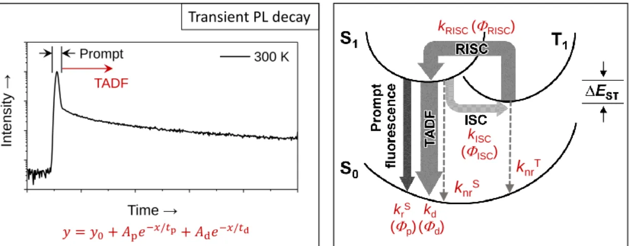
1. 3. 2. Determination of Rate Constants for TADF
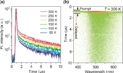
The PL quantum efficiencies (
PL) of the prompt (
p) and delayed (
d) components can be experimentally obtained from the transient PL decay curves (Figure 1-10) and the absolute
PL. The lifetimes of the prompt (
p) and delayed (
d) components were determined by fitting the transient PL decay curves by the following equation:
y = 𝑦
0+ 𝐴
p𝑒
−𝑥/𝜏p+ 𝐴
d𝑒
−𝑥/𝜏d(1-11)
HOMO LUMO
<π π*> Large ΔEST
π π*
n π*
Large orbital overlap between π and π*
<n π*> Small ΔEST
Small orbital overlap between nand π*
HOMO LUMO
Jπ,π*
Jn,π*
11
where, A
pand A
dare the area of the prompt and delayed components. In the presence of ISC and RISC between the S
1and T
1states, the rate constants of the prompt (k
p) and delayed (k
d) components can be expressed by the following formulas:
[19]𝑘
p=
1𝜏p
= 𝑘
rS+ 𝑘
nrS+ 𝑘
ISC(1-12) 𝑘
d=
1𝜏d
= 𝑘
nrT+ (1 −
𝑘ISC𝑘rS+𝑘nrS +𝑘ISC
) 𝑘
RISC(1-13) where k
rSand k
nrSare the radiative and non-radiative decay rate constants of the S
1state, respectively, and k
ISCand k
RISCare the ISC (S
1→T
1) and RISC (T
1→S
1) rate constants, respectively. k
rSand k
ISCare assumed to be much faster than k
nrTand k
RISC. The
p,
d, and
ISCare given by the following formulas:
𝛷
p=
𝑘rS𝑘rS+𝑘nrS +𝑘ISC
=
𝑘𝑟𝑆𝑘𝑝
(1-13)
𝛷
d= ∑
∞𝑘=1(𝛷
ISC𝛷
RISC)
𝑘𝛷
p=
𝛷ISC𝛷RISC1−𝛷ISC𝛷RISC
∙ 𝛷
p(1-14) 𝛷
ISC=
𝑘ISC𝑘rS+𝑘nrS +𝑘ISC
=
𝑘ISC𝑘𝑝
(1-15)
From Eqs. 1-12–1-15, the following equation for k
RISCcan be obtained.
𝑘
RISC=
𝑘p𝑘d𝑘ISC
𝛷d𝛷p
(1-16)
Since the
pexhibits almost negligible temperature dependence, we assume that k
nrS≈ 0 at 300 K. Based on Eqs. 1-12–16, the radiative and non-radiative rate constants corresponding decay efficiencies can be estimated for TADF materials.
Figure 1-10. Transient PL decay of TADF (left) and Postulated PL decay processes for TADF materials (right). k
rSand k
nrSare the radiative and non-radiative decay rate constants of the S
1state, k
ISCand k
RISCare the ISC (S
1→T
1) and RISC (T
1→S
1) rate constants, respectively, k
dis the radiative decay rate constant of the S
1state involving the ISC and RISC process, and k
nrTis the non-radiative rate constant of the T
1state. Φ are corresponding PL quantum efficiencies
𝑦 = 𝑦0+ 𝐴p𝑒−𝑥/ p+ 𝐴d𝑒−𝑥/ d
krS (p)
kISC (ISC) kRISC(RISC)
kd (d)
knrS
knrT Transient PL decay
300 K Prompt
TADF
Time →
Intensity →
12 1. 3. 3. Efficiency of TADF-Based OLEDs
In OLEDs, the most critical parameter is η
ext, which describes the ratio between the number of emitted photons that are extracted to air per injected electrons and injected charge carriers:
η
ext= (γ × η
ST× Φ
PL) × η
out= η
int× η
out(1-18) where γ is the fraction of holes and electrons recombination to form excitons in an emitting layer (EML). η
STis the exciton production efficiency resulting in the radiative transition according to the spin selection rules. Φ
PLis the PL quantum efficiency for radiative decay of the excitons and η
outis the light out-coupling efficiency which is the fraction of the radiated photons from the device into air. γ and Φ
PLare able to realize up to 100% by the advanced device architectures and well-designed molecules by suppressed non-radiative activation,
[6]respectively. η
rcan be changed by emission mechanisms (fluorescence = ~25% and phosphorescence = ~100%). Therefore, assuming η
outof 20%, η
extof fluorescence-based OLEDs are limited to 5%,
[7]whereas phosphorescence-based OLEDs can be achieved high η
extof up to 20%.
[9]In contrary to both fluorescence and phosphorescence-based OLEDs, the directly generated T
1excitons by carrier recombination in TADF-based OLEDs are converted into the S
1state via the efficient RISC. Accordingly, the theoretical maxima of η
intfor TADF- based OLEDs can be given by the following equation:
[10a]η
int= η
S× Φ
p+ η
S× Φ
d+ η
T× Φ
d/Φ
ISC(1-19) where η
Sand η
Tdenote the singlet exciton and triplet exciton production rates (25% and 75%, respectively) and Φ
dis the ISC efficiency (1 – Φ
p). Therefore, the theoretical maxima of η
extfor TADF-based OLEDs can be estimated and achieved up to 20%, assuming η
outof 20%.
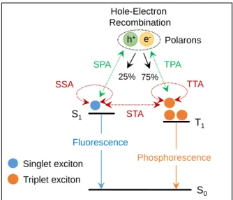
1. 4. Efficiency Roll-Off in OLEDs
The efficiency of OLEDs is typically decreased with increasing current density by exciton quenching, which is drawback for practical lighting applications.
[20]This so-called efficiency roll-off that is attributed to several bimolecular annihilation processes in excited states as follows (Figure 1-11):
i) singlet–singlet annihilation (SSA): SSA is firstly observed in anthracene crystals by
dipole–dipole interactions because the SSA process occurs through Förster energy
transfer.
[21]Therefore, crystalline materials more easily undergo the SSA process than
13
Figure 1-11. Schematic illustration of possible mechanisms of efficiency roll-off in OLEDs.
SSA: singlet–singlet annihilation, TTA: triplet–triplet annihilation, STA: singlet–triplet annihilation, SPA: singlet–polaron annihilation, TPA: triplet–polaron annihilation.
that of amorphous materials, resulting from the higher diffusion constant of ordered materials.
[22]ii) triplet–triplet annihilation (TTA): TTA is mostly relevant to the efficiency roll-off in phosphorescence- and TADF-based OLEDs because both emitters utilize 75% triplet excitons for light emission. Despite the high η
intof nearly 100% in phosphorescence- and TADF-based OLEDs, more serious efficiency roll-off of both devices are usually observed than that of conventional fluorescence-based OLEDs because of triplet excitons possessing long emission lifetimes ranging up to the millisecond range, which lead to higher probability of exciton annihilation than that of singlet excitons having nanosecond scale-emission lifetimes.
[2]Moreover, the emitters are usually required the suitable host materials to confine exciton within emitters for the high EL efficiency as mentioned Section 1. 2. 2. 3.. However, such a host–guest system induces guest–guest TTA as well as host–guest
[23]and host–host
[24]TTA.
iii) singlet–triplet annihilation (STA): STA, which is usually observed in conventional fluorescence
[25]and TADF
[26]-based OLEDs because of utilizing singlet excitons for light emission, can occur by interactions between the singlet and triplet excited states.
h+ e-
S0 S1
T1 25%
Hole-Electron Recombination
75%
Polarons
Singlet exciton
SPA TPA
SSA TTA
STA
Triplet exciton
Fluorescence
Phosphorescence
14
iv) exciton–polaron interaction: the interactions between excitons and electron polarons (e
–) or hole polarons (h
+) by free or trapped charge carriers induces singlet–polaron annihilation (SPA)
[22]and triplet–polaron annihilation (TPA)
[21a,23,27].
Several strategies, to realize the high efficiency at high current density by reducing annihilation, have been introduced, including decreasing the exciton lifetime
[28]and reducing molecular aggregation
[29]of emitters, broadening of the recombination zone in the EML,
[30]and reducing the Förster radius
[31].
1. 5. Motivation and Outline of This Dissertation
Full-color flat-panel displays and solid-state lighting sources based on organic light- emitting diodes (OLEDs) have attracted considerable research interest for over 30 years, because of their high contrast, flexibility, and potentially low manufacturing costs as well as bright and full-color light emissions from thin organic layers. In general, the light emission of excited organic molecules is classified as either fluorescence or phosphorescence. Although fluorescence materials have attracted attention because of their high color purity and high reliability, the internal quantum efficiency of conventional fluorescent OLEDs is limited to 25%, as the recombination of injected electrons and holes generates the lowest excited triplet (T
1) and singlet (S
1) states at a ratio of 3:1. This spin-statistical requirement limits the maximum external electroluminescence (EL) quantum efficiency of fluorescent OLEDs to less than 5%.
Meanwhile, phosphorescence organometallic materials incorporating an iridium or platinum metal center are promising emitters for OLEDs because the internal quantum efficiency of nearly 100% can be attained by harvesting both 25% S
1and 75% T
1excitons for EL emission by accelerated intersystem crossing from the S
1to T
1states, owing to a strong spin–orbit coupling. As an alternative way, thermally activated delayed fluorescence (TADF) has recently gained increasing interest to produce highly efficient OLEDs since the achievement of the internal quantum efficiency close to unity by Uoyama et al. in 2012. Until this discovery, only phosphorescence organometallic materials were regarded as the sole candidates as emitters in high-efficiency OLEDs because phosphorescent OLEDs can achieve external EL quantum efficiency of over 20%. However, these phosphorescence materials still have some drawbacks:
the rarity of the precious metals required for fabrication, toxicity, and difficulty in color
rendering of the three primary colors (blue, green, and red), especially for blue emission. Purely
organic TADF materials can utilize both S
1and T
1excitons for light emission without the use
15
of any precious metal. Thus, TADF molecules can act as a class of next-generation organic light-emitting materials. Therefore, this dissertation focuses on molecular design for highly efficient TADF materials and their application in OLEDs.Outline of this dissertation is as follows.
Chapter 2 deals with a design way for efficient full-color TADF molecules by employing donor and acceptor units with the different electron-donating and electron- withdrawing abilities, respectively. Full-color OLEDs utilizing a new series of wedge-shaped TADF materials as emitters achieved high electroluminescence efficiencies compared with conventional fluorescence-based OLEDs. Chapter 3 and Chapter 4 provide design strategies for highly efficient pyrimidine-based blue TADF molecules employing highly twisted D–A and D–A–D molecular architectures. The newly designed and synthesized series of pyrimidine- based blue TADF materials were investigated their photophysical properties and completely applied to blue TADF-OLEDs. Chapter 5 describes a new high-efficiency blue TADF luminophore based on phenazaborin, and its photophysical properties and potential for application of OLED was investigated. Chapter 6 describes the effect of combining TADF with horizontally oriented dipoles of molecules on both pure thin and doped films in a host matrix as well as OLEDs utilizing a new series of linear-shaped TADF materials as emitters.
Chapter 7 deals with a design concept of bipolar host materials having high thermal stabilities
as well as high lowest excited triplet energies to realize high efficiency TADF-OLEDs with
reduced efficiency roll-off. Finally, Chapter 8 summarizes this dissertation.
16 References
[1] a) J. Kido, M. Kimura, K. Nagai, Science 1995, 267, 1332; b) S. Reineke, F. Lindner, G. Schwartz, N. Seidler, K. Walzer, B. Lüssem, K. Leo, Nature 2009, 459, 234; c) M.
A. McCarthy, B. Liu, E. P. Donghue, I. Kravchenko, D. Y. Kim, F. So, A. G. Rinzler, Science 2011, 332, 570.
[2] M. A. Baldo, D. F. O’Brien, Y. You, A. Shoustikov, S. Sibley, M. E. Thompson, S. R.
Forrest, Nature 1998, 395, 151.
[3] W. Helfrich, W. G. Schneider, Phys. Rev. Lett. 1965, 14, 229.
[4] C. W. Tang, S. A. VanSlyke, Appl. Phys. Lett. 1987, 51, 913.
[5] J. H. Burroughes. D. D. Bradley, A. R. Brown, R. N. Marks, K. Mackay, R. H. Friend, P. L. Burns, A. B. Holmes, Nature 1990, 347, 539.
[6] a) L. Xiao, Z. Chen, B. Qu, J. Luo, S. Kong, Q. Gong, J. Kido, Adv. Mater. 2011, 23, 926; b) M. Zhu, C. Yang, Chem. Soc. Rev. 2013, 42, 4963; c) H. Xu, R. Chen, Q. Sun, W. Lai, Q. Su, W. Huang, X. Liu, Chem. Soc. Rev. 2014, 43, 3259; d) W. Brütting, J.
Frischeisen, T. D. Schmidt, B. J. Scholz, C. Mayr, Phys. Stasus Solidi A 2013, 210, 44;
e) J.-H. Jou, S. Kumar, A. Agrawal, T.-H. Li, S. Sahoo, J. Mater. Chem. C 2015, 3, 2974.
[7] L. J. Rothberg, A. J. Lovinger, J. Mater. Res. 1996, 11, 3174.
[8] a) C. Adachi, M. A. Baldo, M. A. Thompson, S. R. Forrest, J. Appl. Phys. 2001, 90, 5048; b) C. Adachi, M. A. Baldo, S. R. Forrest, M. E. Thompson, Appl. Phys. Lett. 2000, 77, 904.
[9] For cyanobenzene-based TADF emitters: a) H. Uoyama, K. Goushi, H. Nomura, C.
Adachi, Nature 2012, 492, 234; b) T. Nishimoto, T. Yasuda, S. Y. Lee, R. Kondo, C.
Adachi, Mater. Horiz. 2014, 1, 264; c) Y. J. Cho, K. S. Yook, J. Y. Lee, Sci. Rep. 2015, 5, 7859; d) Y. J. Cho, B. D. Chin, S. K. Jeon, J. Y. Lee, Adv. Mater. 2015, 25, 6786; e) Y. J. Cho, S. K. Jeon, B. D. Chin, E. Yu, J. Y. Lee, Angew. Chem. Int. Ed. 2015, 54, 5201; f) S. Wang, X. Yan, Z. Cheng, H. Zhang, Y. Liu, Y. Wang, Angew. Chem. Int.
Ed. 2015, 54, 13068.
[10] For triazine-based TADF emitters: a) S. Y. Lee, T. Yasuda, H. Nomura, C. Adachi, Appl.
Phys. Lett. 2012, 101, 093306; b) A. Endo, K. Sato, K. Yoshimura, T. Kai, A. Kawada, H. Miyazaki, C. Adachi, Appl. Phys. Lett. 2011, 98, 083302; c) K. Sato, K. Shizu, K.
Yoshimura, A. Kawada, H. Miyazaki, C. Adachi, Phys. Rev. Lett. 2013, 110, 247401;
d) H. Tanaka, K. Shizu, H. Miyazaki, C. Adachi, Chem. Commun. 2012, 48, 11392; e)
17
S. Hirata, Y. Sakai, K. Masui, H. Tanaka, S. Y. Lee, H. Nomura, N. Nakamura, M.
Yasumatsu, H. Nakanotani, Q. Zhang, K. Shizu, H. Miyazaki, C. Adachi, Nat. Mater.
2015, 14, 330; f) M. Kim, S. K. Jeon, S.-H. Hwang, J. Y. Lee, Adv. Mater. 2015, 27, 2515; g) D. Y. Lee, M. Kim, S. K. Jeon, S.-H. Hwang, C. W. Lee, J. Y. Lee, Adv. Mater.
2015, 27, 5861; h) W.-L. Tsai, M.-H. Huang, W.-K. Lee, Y.-J. Hsu, K.-C. Pan, Y.-H.
Huang, H.-C. Ting, M. Sarma, Y.-Y. Ho, H.-C. Hu, C.-C. Chen, M.-T. Lee, K.-T. Wong, C.-C. Wu, Chem. Commun. 2015, 51, 13662; i) J. W. Sun, J. Y. Baek, K.-H. Kim, C.- K. Moon, J.-H. Lee, S.-K. Kwon, Y.-H. Kim, J.-J. Kim, Chem. Mater. 2015, 27, 6675.
[11] For sulfone-based TADF emitters: a) Q. Zhang, J. Li, K. Shizu, S. Huang, S. Hirata, H.
Miyazaki, C. Adachi, J. Am. Chem. Soc. 2012, 134, 14706; b) Q. Zhang, B. Li, S. Huang, H. Nomura, H. Tanaka, C. Adachi, Nat. Photon. 2014, 8, 326; c) F. B. Dias, K. N.
Bourdakos, V. Jankus, K. C. Moss, K. T. Kamtekar, V. Bhalla, J. Santos, M. R. Bryce, A. P. Monkman, Adv. Mater. 2013, 25, 3707; d) H. Wang, L. Xie, Q. Peng, L. Meng, Y.
Wang, Y. Yi, P. Wang, Adv. Mater. 2014, 26, 5198; Z. Xie, C. Chen, S. Xu, J. Li, Y.
Zhang, S. Liu, J. Xu, Z. Chi, Angew. Chem. Int. Ed. 2015, 54, 7181.
[12] For benzophenone-based TADF emitters: a) S. Y. Lee, T. Yasuda, Y. S. Yang, Q. Zhang, C. Adachi, Angew. Chem. Int. Ed. 2014, 126, 6520; b) S. Y. Lee, T. Yasuda, I. S. Park, C. Adachi, Dalton Trans. 2015, 44, 8356; c) Q. Zhang, D. Tsang, H. Kuwabara, Y.
Hatae, B. Li, T. Takahashi, S. Y. Lee, T. Yasuda, C. Adachi, Adv. Mater. 2015, 27, 2096.
[13] For spirofluorene-based TADF emitters: a) G. Méhes, H. Nomura, Q. Zhang, T.
Nakagawa, C. Adachi, Angew. Chem. Int. Ed. 2012, 51, 11311; b) K. Nasu, T.
Nakagawa, H. Nomura, C.-J. Lin, C.-H. Cheng, M.-R. Tseng, T. Yasuda, C. Adachi, Chem. Commun. 2013, 49, 10385; c) H. Ohkuma, T. Nakagawa, K. Shizu, T. Yasuda, C. Adachi, Chem. Lett. 2014, 43, 1017.
[14] For heteraborin-based TADF emitters: M. Numata, T. Yasuda, C. Adachi, Chem.
Commun. 2015, 51, 9443.
[15] a) T. Förster, Discuss Farada Soc. 1959, 27, 7; b) B. P. Lyons, A. P. Monkman, Phys.
Rev. B 2005, 71, 235201.
[16] D. L. Dexter, J. Chem. Phys. 1953, 21, 836.
[17] a) Y. Tao, C. Yang, J. Qin, Chem. Soc. Rev. 2011, 40, 2943; b) L. Xiao. Z. Chen, B. Qu, J. Luo, S. Kong, Q. Gong, J. Kido, Adv. Mater. 2011, 23, 926; c) A. Chaskar, H.-F.
Chen, K. T. Wong, Adv. Mater. 2011, 23, 3876; d) K. S. Yook, J. Y. Lee, Adv. Mater.
2012, 24, 3169.
18
[18] a) N. J. Turro, V. Ramamurthy, J. C. Scaiano, Modern Molecular Photochemistry of Organic Molecules, University Science Books, Sausalito, 2010; b) Y. Tao, K. Tuan, T.
Chen, P. Xu, H. Li, R. Chen, C. Zheng, L. Zhang, W. Huang, Adv. Mater. 2014, 26, 7931.
[19] K. Goushi, K. Yoshida, K. Sato, C. Adachi, Nat. Photon. 2012, 6, 253.
[20] C. Murawshk, K. Leo, M. C. Gather, Adv. Mater. 2013, 25, 6801.
[21] a) M. Pope, C. E. Swenberg, Electric Processes in Organic Crystals, Clarendon Press, Oxford University Press, 1982; b) S. D. Babenko, V. A. Bendershkii, V. I. Gol’Danskii, A. G. Lavrushko, V. P. Tychinskii, Chem, Phys, Lett. 1971, 8, 598.
[22] M. A. Baldo, R. J. Homes, S. R. Forrest, Phys. Rev. B 2002, 66, 035321.
[23] M. A. Baldo, C. Adachi, S. R. Forrest, Phys, Rev. B 2000, 62, 10967.
[24] a) Y. Sun, N. C. Giebink, H. Kanno, B. Ma, M. E. Thompson, S. R. Forrest, Nature 2006, 440, 908; b) G. Schwartz, S. Reineke, T. C. Rosenow, K. Walzer, K. Leo, Adv.
Funct. Mater. 2009, 19, 1319; c) T. C. Rosenow, M. Furno, S. Reineke, S. Olthof, B.
Lüssem, K. Leo, J. Appl. Phys. 2010, 108, 11331133.
[25] a) J. Fourny, G. Delacote, Phys. Rev. Lett. 1968, 21, 1085; b) Y. Zhang, M. Whited, M.
E. Thompson, S. R. Forrest, Chem. Phys. Lett. 2010, 495, 161; c) D. Kasemann, R.
Brückner, H. Fröb, K. Leo, Phys. Rev. B 2011, 84, 115208.
[26] K. Masui, H. Nakanotani, C. Adachi, Org. Electron. 2013, 14, 2721.
[27] a) S Reineke, K. Walzer, K. Leo, Phys. Rev. B 2007, 75, 125328; b) J. Kalinowski, W.
Stampor, J. Mezyk, M. Cocchi. D. Virgili, V. Fattori. P. Di Marco, Phys. Rev. B 2002, 66, 235321.
[28] a) H. Yersin, A. F. Rausch, R. Czerwieniec, T. Hofbeck, T. Fischer, Coord. Chem. Rev.
2011, 255, 2622; b) L. Han, D. Yang, W. Li, B. Chu, Y. Chen, Z. Su, D. Zhang, F. Yan, Z. Hu, Z. Zhang, Appl. Phys. Lett. 2008, 93, 153303; c) D. Yang, L. Han, W. Li, B. Chu, Z. Su, D. Zhang, T. Li, G. Zhang, J. Zhu, J. Phys. D Appl. Phys. 2010, 43, 105101; d) D. Song, S. Zhao, H. Aziz, Adv. Funct. Mater. 2011, 21, 2311; e) Q. Huang, S. Reineke, K. Walzer, M. Pfeiffer, K. Leo, Appl. Phys. Lett. 2006, 89, 263512; f) W. Ji, L. Zhang, W. Xie, Opt. Lett. 2012, 37, 2019.
[29] a) Y. Kawamura, L. Brooks, J. J. Brown, H. Sasabe, C. Adachi. Phys. Rev. Lett. 2006,
96, 17404; b) S. Reineke, T. C. Rosenow, B. Lussem, K. Leo, Adv. Mater. 2010, 22,
3189.
19
[30] a) J. Lee, J.-I. Lee, J. Y. Lee, H. Y. Chu, Org. Electron. 2009, 10, 1529; b) G. He, M.
Pfeiffer, K. Leo, M. Hofmann, J. Birnstock, R. Pudzich, J. Salbeck, Appl. Phys. Lett.
2004, 85, 3911; c) M.-T. Lee, J.-S. Lin, M-T. Chu, M.-R. Tseng, Appl. Phys. Lett. 2009, 94, 083506; d) J.-W. Kang, S.-H. Lee, H.-D. Park, W.-I. Jeong, K.-M. Yoo, Y.-S. Park, J.-J. Kim, Appl. Phys. Lett. 2007, 90, 223508; e) S. H. Kim, J. Jang, K. S. Yook, J. Y.
Lee, Appl. Phys. Lett. 2008, 92, 023513; f) Z. M. Hudson, Z. Wang, M. G. Helander, Z.-H. Lu, S. Wang, Adv. Mater. 2012, 24, 2922; g) S. Gong, Y. Chen, C. Yang, C. Zhong,
J. Qin, D. Ma, Adv. Mater. 2010, 22, 5370.
[31] a) W. Staroske, M. Pfeiffer, K. Leo, M. Hoffmann. Phys. Rev. Lett. 2007, 98, 197402;
b) Y. Divayana. X. Sun, Phys. Rev. Lett. 2007, 99, 143003.
20
Chapter 2
Wedge-Shaped Delayed Fluorescence Materials Based on Phthalonitriles and Dicyanopyrazines for Full-Color
Electroluminescence
21 2. 1. Introduction
Various purely organic TADF emitters have been developed to date based on aforementioned design principle in General Introduction,
[1–6]most of them adopt a twisted intramolecular charge transfer (ICT) design, in which the electron donor and acceptor units are incorporated to be orthogonal to each other. Among the reported TADF emitters, 1,2,3,5- tetrakis(carbazol-9-yl)-4,6-dicyanobenzene (4CzIPN)
[1a]combined with an electron- withdrawing isophthalonitrile (i.e., 1,3-dicyanobenzene) with four-fold electron-donating carbazole units is one of the most efficient TADF emitters, exhibiting a maximum external EL quantum efficiency (
ext) of almost 20%
[1a]or even higher.
[7]It has also been reported that by changing the position of cyano groups and the number of carbazole units, the emission spectra of the TADF materials can be tuned. ICT of these molecules has crucial effects on their band gap and luminescence. For the realization of full-color TADF-OLEDs, it is vital to modulate the TADF characteristics and the emission colors systematically using a versatile donor–
acceptor (D–A) system.
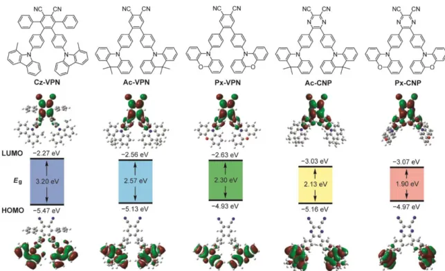
In this chapter, a series of wedge-shaped D–A–D molecules (Figure 2-1), comprising of a central phthalonitrile (VPN) or 2,3-dicyanopyrazine (CNP) acceptor core coupled with various donor units (i.e., 1-methylcarbazole (Cz), 9,9-dimethylacridan (Ac), and phenoxazine (Px)), are reported. -Conjugated phenylene linkers are introduced between the donor and acceptor units to enhance the radiative decay constant of the S
1state to some degree, meanwhile maintaining a small E
ST. These new systems allow a systematic fine-tuning of their band gap and TADF emissions to cover the entire visible range. Full-color EL with a high
extof up to 18.9% can be achieved using wedge-shaped phthalonitrile and dicyanopyrazine derivatives as TADF emitters in OLEDs.
2. 2. Molecular Geometric and Electronic Structures
To understand the effect of variation of the D–A–D structures on the geometric and
optoelectronic properties, quantum chemical calculations were performed on the designed
phthalonitrile- and dicyanopyrazine-based molecules. The calculated energy levels of the
HOMO and LUMO and the respective frontier orbital distributions are presented in Figure 2-
1. The energy levels and molecular geometries in the ground state were optimized by density
functional theory (DFT) calculations. The excited S
1and T
1states were computed using the
optimized structures with time-dependent DFT (TD-DFT) calculations. It is found that the
calculated HOMO–LUMO energy gaps (E
g) can be modulated systematically from 3.2 eV (Cz-
22
VPN) to 1.9 eV (Px-CNP) by a rational combination of donor and acceptor units. The decrease in the E
gfrom Cz-VPN to Px-VPN follows the increasing order of the electron-donating ability of their donor units (Cz < Ac < Px) which consequently affects their HOMO energy levels. Ac- CNP and Px-CNP containing a strong electron-withdrawing dicyanopyrazine core tend to have a lower LUMO energy and a narrower E
gthan the phthalonitrile-based counterparts do. This trend indicates that the donor and acceptor strengths have a great influence on the resulting optoelectronic functionality since the HOMO–LUMO electronic transition dominates the S
1excitation with ICT characteristics.
Figure 2-1. Molecular structures (upper), energy levels and Kohn–Sham orbitals of the HOMO and LUMO (lower) of wedge-shaped phthalonitrile- and dicyanopyrazine-based TADF molecules characterized by DFT and TD-DFT calculations at the B3LYP/6-31G(d,p) level.
The HOMOs of these molecules are predominantly located on the peripheral donor units,
whereas the LUMOs are distributed over the phenylene linkers as well as the central acceptor
core (Figure 2-1). For Cz-VPN, the HOMO is extended slightly to the neighboring phenylene
linkers, owing to the less steric hindrance of the Cz donor units, compared with the Ac and Px
units. The clear spatial separation of the frontier orbitals of all these molecules resulted in small
calculated E
STvalues of less than 0.04 eV (Table 2-1), suggesting the high potential as TADF
emitters. It is also evident that, in the optimized ground-state structures, the dihedral angles
between the peripheral donor units and the nearby phenylene linkers increase in the order of Cz
23
(53–54°) < Px (74–77°) < Ac (87–90°). Such highly distorted geometries of these molecules should arise from the steric effects of the hydrogen atoms and/or methyl groups at the peri- positions in the donor units, contributing to the decrease of the electron exchange energy for the ICT transitions. In contrast, the dihedral angles between the central phthalonitrile or dicyanopyrazine acceptor unit and the phenylene linkers are relatively small (51–54° for Ac- VPN and Px-VPN; 34–35° for Ac-CNP and Px-CNP). These results suggest that the phenylene linker has a stronger conjugation with the central acceptor core than the outermost donor units.
The detail calculated results are summarized in Table 2-1.
Figure 2-2. UV–vis absorption spectra of phthalonitrile- and dicyanopyrazine-based D–A–D type molecules in toluene. The inset shows a magnified view of lower-energy ICT absorptions.
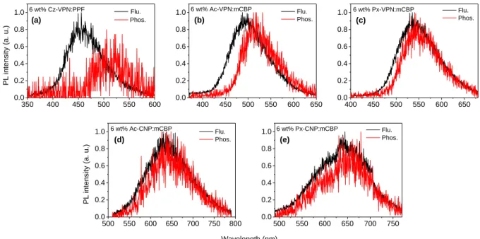
2. 3. Photophysical Properties
The molecular orbital distributions are reflected in the photophysical properties of the
phthalonitrile- and dicyanopyrazine-based materials. Basic photophysical parameters have been
collected from steady-state UV–vis absorption and photoluminescence (PL) spectra and time-
resolved transient PL analyses for toluene solutions and as doped thin films, and the results are
summarized in Table 2-2. As shown in Figure 2-2, these compounds exhibit a broad and weak
absorption band at longer wavelengths in the absorption spectra, which can be assigned to the
ICT transitions from the peripheral donor units to the acceptor core. The ICT absorption band
shifts to lower energies with increasing donor and acceptor strengths, which is well in
accordance with the calculation results.
24
Table 2-1. Triplet and singlet excitation energies (vertical transition), oscillator strength (f), and transition configurations of the phthalonitrile and dicyanopyrazine derivatives calculated by TD-DFT at the B3LYP/6-31G(d,p).
Compound State E (eV) f Main configuration
a)E
ST(eV)
Cz-VPN S
1S
22.836 2.904
0.0181 0.0124
H → L H−1 → L
0.702 0.703
0.039 T
1T
22.797 2.877
0 0
H → L H−1 → L H → L H−1 → L
0.662 0.112 0.673
−0.143
Ac-VPN S
1S
22.183 2.185
0 0
H → L H−1 → L
0.703 0.703
0.002 T
1T
22.181 2.183
0 0
H → L H − 1 → L
0.703 0.703
Px-VPN S
1S
21.934 1.958
0.0099 0.0118
H → L H − 1 → L
0.703 0.704
0.015 T
1T
21.919 1.941
0 0
H → L H− 1 → L
0.700 0.701
Ac-CNP S
1S
21.736 1.736
0 0.0001
H → L H−1 → L+1 H − 1 → L H → L+1
0.692
−0.129 0.692
−0.129
0.003
T
1T
21.733 1.733
0 0
H → L H−1 → L+1 H − 1 → L H → L+1
0.691
−0.133 0.691
−0.134
Px-CNP S
1S
21.524 1.547
0.0336 0.0318
H → L H−1 → L
0.698 0.703
0.040 T
1T
21.484 1.493
0 0
H−1 → L H − 1 → L+1 H−1 → L H → L+1
0.687 0.144 0.687 0.150
a)