The Ring Shaped Energy Release of the Solar Twisted Magnetic Loop
Shinji Koide and Jun-ichi Sakai
Laboratory for Plasma Astrophysics and Fusion Science Department of Electronics and Information
Faculty of Engineering, Toyama University 3190, Gofuku, Toyama 930 JAPAN
Abs tract
We investigate the magnetohydrodynamic (MHD) instability of the magnetic loop in associa
tion with the solar flare_ We use 'safety factor' q to describe the local twist of the magnetic loop where low q value means the strong twist, then it becomes more unstable for the MHD instabil
ity_ We present the q profile on the equilibrium for two types which may correspond to small and large flare. One type corresponding to small flare is the slim cylindrical untwisted magnetic loop in initial stage. When the tube is twisted, low q region is localized around the axis of the center of the loop. We conclude that the localized low q region must be ring shaped. The energy release by MHD instability can be localized with the ring shaped region. The other type is barrel shaped untwisted magnetic loop which may correspond to the large flare. After the twist, low q region is wide along the axis. The MHD instability is caused on the whole magnetic loop, therefore the energy release is global.
§ 1. Introduction
It is well-known from observations that the magnetic loops are twisted in many situations.
The physics of magnetic loops is an important subject associated with phenomena of the solar atmosphere, such as nolar flares, prominences and sun spot, in other astrophysical objects like molecular clouds. It is beleaved that in solar flares magnetic energy stored in many twisted magnetic loops can be explosively released (Svestka, 1976) . Parker (1979) developed the structure of untwisted magnetic loops confined by an external plasma pressure. Browning and Priest (1983) studied the equilibrium structure of an axisymmetric twisted magnetic loop, which is surrounded by a field-free plasma with pressure. Zweibel and Boozer (1985) developed a theory of the force-free magnetic loop which linearize the equilibrium equation and discussed the magetohydrodynamic (MHD) instability of the loop. Recently several authors (Velli et a!.
1990a, 1990b, Foote et a!. 1990) investigated the MHD stability problem of the magnetic loops
- 63-
which ends are line-tied at the photosphere. The non-linear development following the MHD insta
bilities in the magnetic loop has been studied by computer simulation (Steinolfson & Taj ima 1987, Zeidman & Taj ima 1989, Mikic & Schnack 1990, Strauss, 1990) .
corona
rotation
magnetic loop
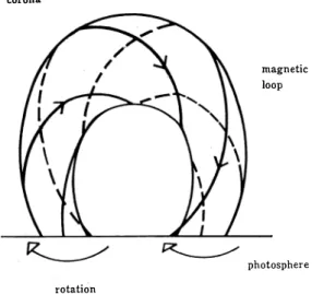
photosphere The twist of the magnetic loop arises from
the rotational motion of the feet of the loop as shown in Figure 1. The strong twisted loop is unstable for the both local or global MHD insta
bilities which cause the magnetic energy release.
In this paper we present a theory for the MHD equilibrium of the solar twisted loop to explain some of the important questions about solar flares. The important questions are;
1. When the energy release starts ?
Figure 1. The solar magnetic loop is twisted with the rotation motion of the photos·
phere.
2. Why the energy release starts at the center of the loops for small one ? 3. Why the energy release of the large flare is global ?
In section 2 we present a theory of twisted magnetic loop to give answers for the above questions. In section 3 we discuss the above questions, based on results obtained in the previous section. As concerned with the second question, we conclude that the energy release in the loop is localized and ring shaped. These results imply the ring shaped Ha brightening on the photosphere and the ring shaped source of electromagnetic radiation on the top of the loop. In section 4 we summarize our results.
§2. Model-of Tw.isted Magnetic Loop
The solar magnetic loops associated to the flare are shaped as arch which dimension L is spread from 1X10⁶ m to 2X10⁷m. (Tanaka, 1987) For simplicity, we assume that the magnetic loop is straight and fixed at the ends of the photosphere. The magnetic loop is twisted by the rotation of the root of the loop at the photosphere. The initial magnetic field is assumed to be straight which magnetic field components are given by
Br=O,
B8=0, ( 1 )
Bz=B�(r),
Where the cylindrical coordinate ( r, {),z ) is employed as shown in Fig. 2. The ends of the loop are twisted externally at z = L /2 and z = -L /2 where the angle of rotation is !l {) ( r ) /2,-t::. {) ( r ) /2, respectively. The radial direction edge of the loop is fixed at r = a where a may be infinite. The magnetic field is governed by the MHD equilibrium equation
7 X B-\7 p -p \7 4> = 0, ( 2 )
in addition to the boundary condition where 7 ,B , P, P , 4> are current density, magnetic field flux
Sakai : The Ring Shaped Energy Release of the Solar Twisted Magnetic Loop
density, pressure, mass density and gravitational potential, respectively.
z=-2 L ond
edge
z=O
center
z=a L ond
2 .JO
We focus on the magnetic field struture in the MHD equiliblium due to the rotation at the ends. One field line of the initial magnetic field is char
acterized by ( R , 8 = 0 , z ) . After the rotation at the ends keeping MHD equiliblium, the twisted magnetic field line is labeled by ( r = f ( R, z ) , 8 = f8J ( R, z ) , z) , where we assumed that the twisted magnetic loop is axisym
metric (a I a8 = 0). The magnetic field is given by
B r( r ,z ) =
at(R,z) R B�(R)
Figure 2. The cylindrical model of the twisted mag·
netic loop is employed. The cylindrical coordi
nate (r, 8, z) is used. The photosphere is corre
sponding to z=L/2, -L/2. The twisted magnetic loop is shrunk around the center of the loop for the initial MHD equilibrium loop or expanded for the inner magnetic pressure is high enough.
az
R B�(R,z) ae B8(r,z)= aj(R,z) --az ·
aR
Bz(r,z) RB�(R,z)
( 3 )
where r and R are related as r = f ( R, z ) . It is confirmed that the above expression of the magnetic field satisfies div B = O, using a simple relation
Br---az-Bz. _at ( 4 )
From taking inner product of B with the equation (2) , we find that
B· ('V P + P 'Vf/1) = a az ar 1 (_g_p_+ P a4> ar ) +_g_p___+ az P a4> ar = O .
Each component of the equation (2) is written as
. . _ap paf/1
JoBz- JrBz-a-:r+ ar • jzBr- jrBz=O,
( 5 )
( 6 ) ( 7 ) ( 8 ) where it is shown that equation (6) and equation (8) are the same equation according to equation
(5) . It is noted that equation (7) implies also the poloidal symmetry. By equations (3) and (7), we get
�z a� ( atjaR RB� ��) = O . ( 9 )
We can define the function of the only R,
- 65-
2n/ ae 0 F(R) ajjaR az RBz.
From equations (3) and (6) we find that,
- a� [�;��j����: (RB�)2]+ a� [ /fJJ;R (RBn2]
1+(ajjaz)2 o 2 _ 1 a 2 (ap ac�> )
+ 2/2(ajjaR) (RB z) -2/ aRF +! aR+ P aR ' The plasma pressure is· taken as
P = P 0(R)
for isobaric change of the state, and as
- 0 ( 1 JL12 aj2 )-r
p-p (R) R L -u2 aR d z
for adiabatic change of the state. The gravitational potential is taken as 4> = 4> 0(/ (R,z )) ,
(1 0)
(11)
for external gravitation force. In this paper, we do not treat the effect of the pressure and gravitation.
If we introduce the flux function Y,, defined as Y,= 2n J:B�(R') R' d R' ,
we can rewrite equation (11) as
a [1+(a/ ;az )2] a [ at ;az J
- ay, 2/ (a J ;ay,)2 +a:z · J (a J ;ay,)
1 + ( a J 1 a z ) 2 1 a ( a p ac�> )
+ 2/2(aJ;ay,) 2/ ay,F2+(2n)2/ aR + P aR • (12) and equation (10) as,
J aa
F(R)= (aj jaY,) az · The equation (12) is the same one derived by Zweibel et al. (1985) , if we neglect the second term of the right hand side, showing pressure and gravity effect. This equation is a gener
alization with the effect of the presure and more useful compared with equation (12) , when we consider the field reversal configu
ration in magnetic loops which is interesting object in solar flare.
The boundary condition is given by f ( R, ± i ) = R (13)
e(R. ± i )= ± �/, (14)
at z = ± i and
at r =a .
f ( a , z ) = a , (15)
(a)
lower corona
photosphere
magnetic tube
(b)
upper corona
Figure 3. The two types of the solar loop corresponding to (a) the small flare and (b) large flare. The loop of small flare is slim because of the external magnetic field is strong. That of the large flare is barrel shaped because of the week mag
netic field on the upper corona. The difference of the figure of the loop causes the different MHD instability for two types twisted magnetic loops.
Sakai : The Ring Shaped Energy Release of the Solar Twisted Magnetic Loop
The important quantity, so called safety factor q which characterize the stability criterion of MHD instabilities like kink instability and tearing instability is given as
q(r z)=27trBz(r.z) 27t
' - L Be (r,z) L(a®jaz) According to equation (11) we get
(16)
q (ajlaR)R q(R, ± �). (17)
By using equation (16) we find the relation between the rotation angle of the twisted loop and shrink radius f as
Lt:.fJ _ 1
J-� R (a f jaR) dz
27t - q (R,±L/2) --f f
Therefore we find that
27t <U>
q = !lfJ(R) U '
where breakdown parameter of uniform shrink is defined as u R(aJ;aR)
f
(18)
(19) and the average of the breakdown parameter U along the toroidal direction of the loop is given by
L
_ 1 jT
<U>=y .lUdz.
2
As f (0, z) = 0, �� (0, z) =t=O, we find that
U(O, z) = 1
so the safety factor on the axis is constant, q (0, z) = t:.fJ(O) . 27t
It is noted that low q value region on the axis is not localized.
§3. Ap p lication to the Solar Flare
(20)
(21) (22)
The magnetic loops associated to the solar flare are divided to two types; the large loop and small one. The observation shows that the small flare is impulsive and has local activity, on the other hand, the large one is gradual and has global activity (Tanaka 1987) . The energy of the flare activity is supplied by the rotation motion of the root of the magnetic loop on the photos
phere for both types. The reason why the magnetic energy release is different between these two types is that of the figures of the untwisted magnetic loop between two types. The shape of the loop is swelled for the large one as like barrel, on the other hand, is slim for the small one. The barrel shaped magnetic loop is twisted strong near the ends, on the other hand, the slim magnetic loop is twisted strong around the center except on the axis.
The strong twist is described as low q value. The low q value region is unstable for MHD instability especially for kink instability (Bateman, 1987) . We present the estimation of the q value for both garrel shaped magnetic loop and slim one. We treat two different types of
- 67-
magnetic loops on the MHD equilib
lium before the twist as shown in figure 4 (c) and (d) corresponding to slim cylindrical loop and barrel shaped one. Therefore we must treat the initial magnetic field as shown in figure 4 (a) and (b) corre
sponding to the slim magnetic loop and barrel shaped one, respectively.
After the magnetic loop is twist
ed, the both types of the loop are shrunk from the untwisted loop on the MHD equiliblium (figure 4 (c) and (d)). Nevertheless, barrel shaped loop is expand in comparison with the loop of figure 4 (b) . We try to describe the shrink and expansion of the loop as
!=R+ c (z )R(R2-a 2), (23) where c (z) is positive for the shrink loop and negative for the expand one like in figure 4 (e) and (f).
We assume that the breakdown parameter of the uniform shrink U is given by
U=3- 2 cR2 (24)
1 + 1-ca2
For the shrink loop, f/a at the center is describe as shown in solid line of figure 5 (a) where c is 0.5, on the
end
end
end
(a) cylindrical tube
(c)
(e)
magnetic tube
end
end
end
(b) barrel shaped
(d)
(f)
magnetic tube
end
end
c
end
Figure 4. The cylindrical model of the two types of the magnetic loops; right side corresponding to the small flare or slim cylindrical loop and left side to the large flare or barrel shaped loop. (a) and (b) are initial cylindrical loops without MHD equilibrium stage for the analytic method. (c) and (d) are untwisted loops with MHD equilibrium. (e) and (f) are twisted loops with MHD equilibrium.
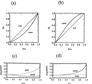
other hand f/a at the ends is describes as broken line where c is zero with boundary condition (13). For the expand loop, f/a at the center is describe as shown in solid line of figure 5 (b) where c is-0.5, at the ends c is zero too. The average value <U> for the slim cylindrical loop and the barrel shaped one is given as c=O.l and c=-0.1, respectively. We further assume that the rotation angle of twisted magnetic loop on the ends is
6..8(R)= (6..8(0)-I:!JJ(a)) { 1-(�r} +t:..8(a), where power 1 is always 4, 6..8 (a) I 6..8 ( o) is 0.7.
(25)
Figure 5 (c) and (d) show q profile of two types of the twist loops for the slim magnetic loop and garrel shaped one according to the equation (18). For the slim magnetic loop, the q value
Sakai : The Ring Shaped Energy Release of the Solar Twisted Magnetic Loop
(a)
1.0
0.8 •' ....
..
•'
0.6 onds •' •'
� •'
;;:, •' •' •'
0.4 •'
, ... ····
center
0.2 •'
.. ··
·"'
.. •'
(b)
l.O,..,.,-.,..,....,�.,.,..,..,.,...,...,.., ,
,.
•'
0.8 center 0.6
0.4
0.2 ,. •'
•' .. ···
. .. ····'
,. •' ,•' ends
•' , .
•'
•'
of the center is smaller than that of the ends. Therefore low q region is localized around the center of the loop.
It is noted that q value on the axis is larger than that of the edge, so low q region is ring shaped as shown in fig
ure 6 (a) . The MHD instability is caused like ring shaped, then Ha emis
sion and electromagnetic radiation source is expected to be ring shaped.
By Abel transformation technic, we may be able to observe the ring shaped structure of the source of electromag
netic wave directly.
, ...
•'
... ··"
0.0 0.0 0.2 0.4 0.6 Ria
(c)
3.0 8 2.5
<D 2.0
"'- ends
r; 1.5
1.0
0.5 0.0 0.2 0.4 0.6
Ria
0.8 1.0
...
•'
center
0.8 1.0
O.O"'-'--'-'--'--'-'-'�..._,c.>o.L.._._._, 0.0 0.2 0.4 0.6 0.8 1.0
Ria
(d)
tliL::::;;;;;;;�
0.0 0.2 0.4 0.6 0.8 1.0Ria
For barrel shaped loop, q value on the center is larger than that of the ends as shown in figure 6 (b) . The global MHD instability is caused which is observed as the wide magnetic
Figure 5. The safety factor q is presented for slim cylin
drical twisted loop (c) and barrel shaped twisted loop (d) 0
energy release.
Corresponding to the first question, it is noted that the q value at the axis is given as equation (22). By one more rotation twist, q value cuts one around the axis and the (internal or external) kink instability is caused at least (Bateman, 1978) . For both slim or barrel shaped magnetic loop, after the one rotation twist, kink instability is unsta
ble. The radius of the loop on the root is 1Xl06m, lXlO' m for small and large one respectively. The rotation velocity is lOOm/
s. So the time when the kink instability is caused is one day and ten days order for the small and large loop, respectively.
The other thinking exists for the treat
ment of the MHD instabilities (H. Sugama) .
(a)
photosphere low q region
(b)
photosphere Figure 6. The low q region is described by
shadow. The small flare becomes MHD unstable from the center of the loop, on the other hand large loop is unstable for whole loop. It is noted that the magnetic energy release of the small flare begins from the ring shaped region.
For the barrel shaped magnetic loop, the instabilities is stabled by the strong magnetic shear. On the other hand, the magnetic shear is week of the slim cylindrical loop at the center, therefor the instabilities is easy to be caused on the center of the loop.
- 69-
§4. Conclusion
We investigated the MHD equilibrium of the line-tied magnetic loop which is twisted at the ends of the magnetic loops for both the slim cylindrical loop and barrel shaped one. New treatment of the equilibrium for the non-force-free magnetic field was given in general, though it is difficult to get the exact explicit solution. The important value q value which describes the twist of the magnetic loop is evaluated to discuss the linear MHD stability. The barrel shaped loop which may corresponding to the large flare loop is twisted in wide region along the axis. On the other hand, the slim cylindrical loop is twisted strong in the center of the loop. The new prophecy is that the energy release region is localized far form the axis around the center of the magnetic loop in this case.
The exact treatment of the time evolution of the equilibrium and instabilities will be given elsewhere by the three dimensional MHD simulation with semi-implicit method which had been developed for the field reversal pinch fusion devise.
Acknowledgement
One of the authors (J.S.) would like to thank a Grant-in-Aid for Scientific Research from the Ministry of Education.
References Bateman, G., 1978, MHD Instabilities', (MIT Press) Foote, B. J_, Craig, L ]_ 1990, Ap. J_, 350, 437 Mikic, Z., Schnack, D. D., 1990, Ap. J_, 361, 690
Parker, E. N ., 1979, 'Cosmical Magnetic Fields', (Clarendon Press) Steinolfson, R. S., Tajima, T., 1987, Ap. J_, 322, 503
Strauss, H. R., 1990, ]_ Geophys. Research 95, 17, 145 Sugama, H., private comunication (1991)
Svestka Z., 1976, 'Solar Flares', (D. Reidel Publishing Company) Tanaka, K., 1987, Pub!. Astron. Soc. Japan 39, 1
Velli, M., Hood, A. W. 1990a, Ap. J_, 350, 419
Velli, M., Einaudi, G., Hood, A. W. 1990b, Ap. J_, 350, 428 Zweibel, E. G., Boozer, A. H., 1985, Ap. J_, 295, 642 Zeidman, E. G. Taijima, T., 1989, Ap. ]., 338, 1139