HYDRAULIC DESIGN OF IN-GROUND STILLING BASIN UNDER SUBMERGED JUMP CONDITIONS
FOR FLOOD MITIGATION DAMS
Mohammad MESHKATI SHAHMIRZADI1, Tetsuya SUMI2
1Member of JSCE, Ph.D. Student, Disaster Prevention Research Institute, Kyoto University (Gokasho, Uji, Kyoto 611-0011, Japan)
2Member of JSCE, Professor, Disaster Prevention Research Institute, Kyoto University (Gokasho, Uji, Kyoto 611-0011, Japan)
Forced submerged jumps within a non-prismatic stilling basin, named in-ground stilling basin, were experimentally investigated. An in-ground stilling basin (ISB) is a newly popular concept for stilling basin downstream of flood mitigation dams (FMDs). In FMDs usually one bottom outlet is located in the centerline and the width of the stilling basin is much wider than the width of the bottom outlet, which leads to a small expansion ratio, k, for the outflow. This study experimentally investigates the flow patterns and velocity reduction, within ISB downstream of FMDs, under different hydraulic and geometric conditions. Finally, an innovative design guide-line is proposed considering downstream flow requirement.
Key Words: Flood mitigation dam, submerged hydraulic jump, in-ground stilling basin.
1. INTRODUCTION
Stilling basin is a well-known hydraulic structure located below dam’s bottom outlet, chutes and culverts. The main objective of this structure is to dissipate the excess energy of outflow to reduce the risk of undesirable scouring in river system.
However, the function of stilling basin in a flood mitigation dam (FMD) is not only to dissipate the excess energy of flow in flood events, but to let the flow, sediment and fish pass through the structure unobstructed during normal river flow condition.
Thus, it is highly necessary to improve the design of stilling basin, in order to fulfill the advantages of FMDs.
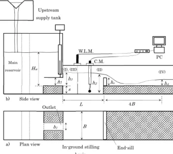
These facts bring the authors to conduct an experimental investigation on the numbers of proposal solutions. The solution discussed in this paper is to dig out the apron of stilling basin and create what it has been called, in-ground stilling basin (ISB), a non-prismatic stilling basin with a sudden transversal enlargement combined with a vertical abrupt drop at its upstream end. The schematic side and plan view of constructed model setup and the main governing parameters considered in this study was shown in Fig. 1.
State of art provides considerable number of experimental studies devoted to hydraulic jumps in
non-prismatic stilling basins. Past studies can be classified into three main categories as: hydraulic jump in case of only sudden enlargement in the flume width1), 2), 3) only abrupt drop at the bed4) and combination of both sudden expansion and abrupt drop 5), 6), 7)
.
The past studies on hydraulic jump in sudden expansion and abrupt drop, mostly conducted by adjusting the tail-water level, being far from the real condition; whereas in present study there is no control on tail-water and the hydraulic jump was forced by an end-sill, similar to the real condition. A forced hydraulic jump within a confined and complex structure such as ISB has yet to be solved in the literature. This study specifically focused on a small expansion ratio (=bottom outlet width/ ISB width) of 0.2, as it is more practically common and causes a periodic and unstable flow pattern rather than larger expansion ratios 2).
Present research experimentally investigates the hydraulic characteristics of the forced hydraulic jump in an ISB and attempts to classify the possible flow patterns within it under different hydraulic and geometry conditions. Lastly, using successful experimental results a design procedure was developed for the forced submerged jump within ISB, concerning the flow requirements at ISB downstream.
Journal of Japan Society of Civil Engineers, Ser.
B1 (Hydraulic Engineering), Vol. 69, No. 4, I_79-I_84, 2013.
2. MATERIALS AND METHODS
(1) Experimental setup
The model setup constructed for this study is the scale representation (length scale ratio equal to 1/40) of the hydraulic flow situation of three flood mitigation dams in Japan (Masudagawa, Tsuzuki and Mogamioguni). This model consists of a horizontal rectangular flume, 0.5 m width, 0.5 m deep and 9 m long. A centrifugal pump was employed to support the recirculating water system throughout the model. The upstream supply tank was equipped by a calibrated 90 degree V-notch weir. To measure the water head above the V-notch weir a point gage was used, and then average time-volume method was utilized to obtain the relationship between water head and the pertinent discharge. Two pierced plates, also, were installed inside of the main reservoir to attain the laminar outflow discharge from its bottom outlet; so that a uniform supercritical flow with a thickness equal to the bottom outlet was finally plunged into the ISB.
(2) Experimental measurement
The basic data collection procedure was the same for all of the experiments run. For each test digital photographs were taken from side and plan view of ISB and visual observations were recorded using high resolution digital camera. A water level meter was used to measure the water depth and its fluctuation throughout ISB. The sampling frequency for water level meter was set to 50 HZ. Using an electro-magnetic current meter the 3D component of velocity was measured in different transversal and longitudinal cross sections for each test run. At every section the velocity was measured at 2.5 cm interval. Accordingly, the sampling frequency was set to 50 HZ.
Fig. 1 Schematic side and plan view of the model setup.
Table 1 Experimental condition.
b1/B L/B s/h1 he/h1 Fr1
0.2
1.5 3 0, 0.8, 1.6 & 2.4 2.8-5.1
2 1, 2 & 3 0, 0.8, 1.6, 2.4 & 2.7 2.8-5.1
2.5 3 0, 0.8, 1.6 & 2.4 2.8-5.1
(3) Experimental condition
The experiments were carried out under different ISB geometries as follows: ISB length (L= 75, 100 and 125 cm), drop height (s= 5, 10 and 15 cm), however, the ISB width for all experiments was the same B= 50 cm equal to the width of flume. For each ISB geometry configuration, different geometry of end-sill with various heights (he= 0, 4, 8, 12 and 13.5 cm) has been systematically examined to obtain the optimum case. The end-sills were placed vertically above the positive step and perpendicular to the longitudinal axis of flume. In addition to the three different Froude number of supercritical flow at the bottom outlet (namely Fr1= 2.8, 4.9 and 5.1), only one dimension of bottom outlet (h1= 5 cm and b1= 10 cm) was examined, thus, creates an expansion ratio of k=0.2 (k=b1/B), similar to the average practical expansion ratio for FMDs. Table 1 shows the experimental condition considered in present study.
3. RESULTS AND DISCUSSION
(1) Flow pattern classification
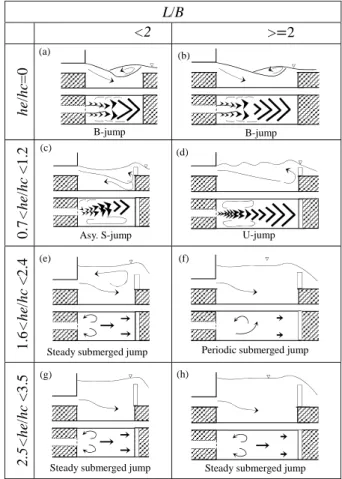
Depending on the geometry of ISB, five different jump types have been observed within ISB including: B-jump, S-jump, U-jump, periodic submerged jump and steady submerged jump 7) (Fig.
2). It can be determined that the type of hydraulic jump was less dependent on Fr1, and more dependent on the end-sill height he.
Fig. 2 Hydraulic conditions for five flow patterns with change of normalized end-sill height and normalized ISB length, for
s/h1=3, Fr1=2.8-5.1
(I), (III)
a) Plan view Upstream supply tank
Hw
W.L.M.
In-ground stilling basin Main
reservoir
h4
he C.M.
4B (II) (IV)
s h1
b1
PC
L
End-sill B
b) Side view Outlet
h2
h3
Flow pattern 1: B-jump was observed only in case of the ISB without end-sill (Fig. 3a and b), in which a non-submerged nape plunges into the ISB. At the lateral side of the nape air entrained into the water and minor jumps were created in two parallel lines.
By getting far from the outlet the surface roller becomes wider and occupied whole the width of the channel.
Flow pattern 2: For a short ISB length (L/B<2) and shorter end-sill height (0.7<he/hc<1.2), the expanded supercritical outflow turned to the left side and formed an oblique spindle of rollers at the surface of water (Fig. 3c). Simultaneously, at the opposite side of the channel, right side, a big eddy was formed.
This flow pattern is known as asymmetric S-jump, which was distinguished as a dominant flow pattern for short ISB with low end-sill height.
Flow pattern 3: A longer ISB with low end-sill height established a different type of flow pattern (Fig. 3d), named U-jump. In this case, a narrow and symmetric super critical current was observed along the centerline of ISB, in which the rollers front were continuously converging and diverging. Two eddies with approximately equal size, also, formed at both side of the central super critical current.
Flow pattern 4: A short ISB length (L/B<2) combined with a medium height of end-sill (Fig.
3e), established a steady and symmetric flow, named steady submerged jump. While, the longer one (L/B>2) turned to be much unstable and periodic, named periodic submerged jump (Fig. 3f).
The shorter ISB with medium height of end-sill may be an optimum case as a point of view of jump stability and compactness.
Flow pattern 5: Lastly, in case of a very tall end-sill (2.5<he/hc<3.5), variation of length did not considerably effects on flow pattern within ISB (Fig. 3g and h).
(2) Dissipation effect of in-ground stilling basin The normalized velocity reduction is plotted against different normalized parameters to provide a better vision in their individual effects on dissipation mechanism within ISB.
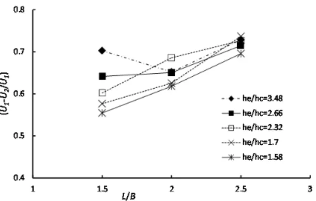
Fig. 4 illustrates the normalized velocity reduction, U1-U2/U1, between section I and II, as a function of the normalized ISB length (L/B). U1 is the initial outlet velocity and U2 is the maximum velocity just upstream of end-sill. In short ISB cases (L/B=1.5) the change in end-sill height causes a large change in normalized velocity reduction, however, for long ISB (L/B=2, 3) the changes in end-sill height results in very small changes in normalized velocity reduction. It demonstrates that in shorter ISB, the normalized velocity reduction depends more on the normalized end-sill height,
he/hc, in comparison with the longer ISB. The overall trend shows that increasing the normalized ISB length may increase the magnitude of velocity reduction. Moreover, for a given normalized end-sill height, he/hc, the longer ISB shows a greater value of normalized velocity reduction (Fig. 5). Moreover, the effect of normalized end-sill height, he/hc, on normalized velocity reduction may differ between short and long ISB length. In case of shorter ISB, by increasing the he/hc, velocity reduction always increased while in case of longer ISB after he/hc=2 the normalized velocity reduction did not change and remained constant. It reveals that a longer ISB may provide us a shorter end-sill height.
Fig. 6 and 7 depict the influence of drop number (s/h1) on velocity reduction within ISB respectively for Froude number equal to 2.8 and 4.3. With an overall view on the data plotted in Fig. 6, it can be established that a shallower ISB (s/h1=1) with medium height of end-sill (he/hc=1.8) is an optimum geometry for end-sill and step (highest velocity reduction). Having said that, increasing the Froude number from 2.8 to 4.8 slightly shifted the optimum drop number from s/h1=1 to s/h1=2 (Fig.7). In general, for a Froude number between 2.4 to 4.3, the maximum performance of ISB regarding to velocity reduction, may occur for s/h1=1 to 2 and he/hc=1.8 to 2.9.
Fig. 3 Schematic side and plan view of the flow patterns under different hydraulic and geometric conditions.
L/B
<2 > 2
he/hc=00.7<he/hc <1.21.6<he/hc <2.42.5<he/hc <3.5
(a) (b)
(c) (d)
(f)
(g)
B-jump B-jump
Asy. S-jump U-jump
Steady submerged jump
Steady submerged jump Steady submerged jump Periodic submerged jump (h)
(e)
0 0.2 0.4 0.6 0.8 1
0 1 2 3 4
U1‐U2/U1
s/h1
he/hc=0 he/hc=0.9
he/hc=1.8 he/hc=2.9 0
0.2 0.4 0.6 0.8 1
0 1 2 3 4
U1‐U2/U1
s/h1
he/hc=0 he/hc=0.9
he/hc=1.8 he/hc=2.9
Fig. 4 The normalized velocity reduction within ISB versus L/B for periodic and steady submerged jump with Fr= 2.8-5.1 and
s/h1=3.
Fig. 5 The normalized velocity reduction within ISB versus he/hc for periodic and steady submerged jump with Fr= 2.8-5.1
and s/h1=3.
Fig. 6 The normalized velocity reduction within ISB versus s/h1 for Fr=2.8 and L/B=2.
Fig. 7 The normalized velocity reduction within ISB versus s/h1
for Fr=4.3 and L/B=2.
Fig. 8 The normalized velocity reduction between section I and IV versus he/hc.
Additionally, for a given drop number (s/h1) a taller end-sill provides better velocity reduction.
However, increasing the normalized end-sill height from he/hc =1.8 to 2.9 did not significantly change the magnitude of normalized velocity reduction within ISB. Thus, the drop number (s/h1) equal to 2 and the normalized end-sill height (he/hc) equal to 1.8 may are the optimum test cases.
Fig. 8 illustrates the normalized velocity reduction between section I and IV (downstream of ISB). U4 is the average velocity of flow at section IV. The overall trend of data plotted in this figure shows by increasing the normalized height of end-sill the normalized velocity reduction is reducing. In other words, in contrary with the necessity of taller end-sill to create a steady submerged jump within a confined space, the taller end-sills negatively reproduce the higher flow velocities at ISB downstream.
(3) Design procedure of in-ground stilling basin
a) Determining the sequent depth
So far, in preceding sections, it was shown that considering a medium end-sill and drop height for ISB could effectively reduce the velocity of flow.
Also, this combination of end-sill and drop resulted to stable and steady flow known as steady submerged flow. Thus, hereafter the design guide lien producer is proposed only for steady submerged flow.
To calculate the sequent depth, h2, for the forced submerged hydraulic jump, the momentum equation was applied, neglecting the bed shear stress, between section I and II in (see in Fig. 1).
(1)
where h is the submergence depth at the face of drop, h is the sequent depth upstream from the end-sill, U1 is the initial outlet velocity, U1=Q/(b1×h1), and is the average velocity at
section II, =Q/(B×h2), Qis the outflow discharge, is the density of water, and is the specific weight of water. After substitution of non-dimensional parameters in Eq. 1 and simplification, the preceding equation can be expressed as:
2 2 2 0 (2)
where Y2 is the normalized sequent depth, Y2=h2/h1, S is the drop number, S=s/h1, and k is the expansion ratio, k =b1/B. Fig. 9 shows the comparison between the predicted h2 using Eq. 2 and the measured sequent depth. As can be seen, Eq. 2 provides an amenable prediction of measured sequent depth.
b) Determining the end-sill height
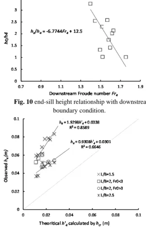
The end-sill height is obtained using Fig. 10, selecting a desire Froude number for the downstream from end-sill (Fr4) on the horizontal axis, and then finding a corresponding he/h4 value on the vertical axis. The water depth at ISB downstream, h4, can be calculated from the selected Fr4 and the design discharge. It should be taken into account, the energy loss over the end-sill (free fall flow) is not negligible and it is varied depend on the end-sill height. The energy over the end-sill can be calculated using critical depth (hc) and end-sill height (he). If it assumed that, there is no energy loss for free fall flow over the end-sill, the energy downstream of ISB is equal to the energy at the top of end-sill as below:
(3)
where hc is the critical depth, B is the width of the channel, h4 is the water depth at ISB downstream, Q is the design discharge and g is gravity acceleration.
The comparison between the measured values of energy at section IV, and the results obtained by theoretical method (Eq. 3) demonstrates that the existence of considerable energy loss over the end-sill (Fig. 11). Therefore, empirical equations were proposed to map the h’4 assuming no energy loss over the end-sill to the measured values of h4. By knowing the h4, the width of channel, B, as well as the design discharge, Q, all the necessary parameters for the boundary condition at the downstream of end-sill would be completed.
c) Determining the ISB length
The proper estimation for the ISB length (L), or in other words end-sill location, is crucial. If end-sill locates too close to the outlet, the jump would not have enough space to be induced. In other hand, a
Fig. 9 Predicted normalized sequent depth, Y2, using Eq.4 versus the measured sequent depth.
Fig. 10 end-sill height relationship with downstream boundary condition.
Fig. 11 Predicted downstream water depth assuming no energy loss, h’4..
long ISB is not cost-efficient. In practice, the length of a classical hydraulic jump (Lj), 4 to 6 times of sequent depth (h2), is being used for design purposes. This method may not suitable to obtain the ISB length herein, due to the presence of tall end-sill and submerged hydraulic condition. The ISB length (L) can be obtained using Eq.4 proposed by Ohtsu et al. 2).
1.7 1.79 (4) where HL is the head loss due to submerged hydraulic jump and H1 is the total head at the drop face, which can be define as:
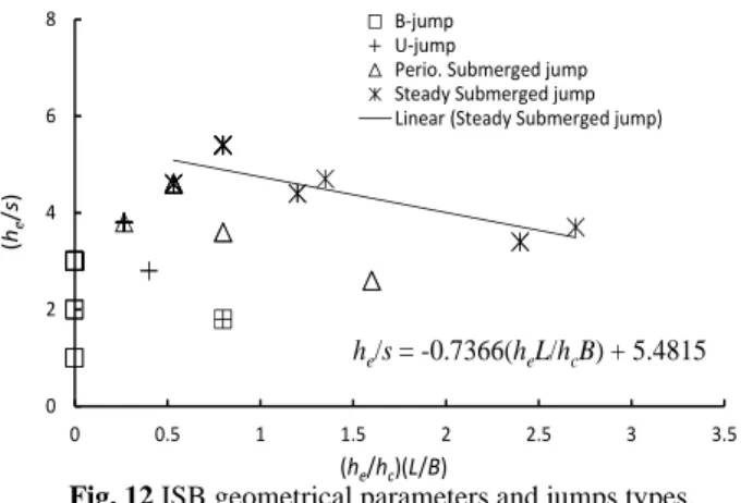
he/s= -0.7366(heL/hcB) + 5.4815
0 2 4 6 8
0 0.5 1 1.5 2 2.5 3 3.5
(he/s)
(he/hc)(L/B) B‐jump U‐jump
Perio. Submerged jump Steady Submerged jump Linear (Steady Submerged jump)
(5)
U1 is the initial outlet velocity, and is the average velocity at section II. The Eq. 6 is the non-dimensional form of Eq. 5 considering expansion ratio, k, as well as drop number, S, to predict the energy loss within ISB. The value obtained by Eq. 6 is input for Eq. 4.
/ (6)
d) Determining the drop height
The drop height, s, can be found using steady submerged jump data in Fig. 12. The known values of hc, L, B and he with the linier equation fitted to the steady submerged jump data may provide an appropriate estimation of drop height to be used in design procedure.
Fig. 12 ISB geometrical parameters and jumps types.
e) Proposed design procedure of ISB
For a horizontal apron of ISB with a negative step at upstream end and an end-sill at its downstream end, following design procedure can be proposed:
1) Given the upstream boundary condition including the design discharge, Q, dimensions of bottom outlet, b1 and h1, approach Froude number, Fr1, and river channel width, B.
2) Use the upstream boundary condition to calculate the critical depth, hc.
3) Select a suitable he and L and then s by referring from Fig. 10 to 12 as well as Eq. 4 to 6, considering stable submerged hydraulic jump.
4) Check the obtained water depth downstream from the end-sill, h4, and downstream Froude number, Fr4, under assumption of no energy loss. If necessary, modified h’4 can be calculated with Fig. 11 by considering the energy loss by free fall flow over end-sill.
5) Repeat steps 2 to 3 until the downstream condition will come to be acceptable level.
4. CONCLUSION
This paper investigates forced hydraulic jumps within an in-ground stilling basin (ISB). The observed flow patterns within ISB were classified into five main groups. The main governing parameters were found to be the height of end-sill, he, and the ISB length, L, while the variation of Fr1 did not lead to a considerable effects on the flow pattern and energy loss function within ISB.
It was concluded that the presence of end-sill is vital to establish a compact hydraulic jump, although a tall end-sill can negatively accelerate the downstream velocity due to the free fall flow over the end-sill. A medium ISB length combined with a medium end-sill height (1.6<he/hc<2.4) provides a stable symmetric submerged jump with greater velocity reduction.
The effect of drop number (s/h1), also, was examined in this study. It was found that, considering a medium depth for ISB can positively improve the velocity reduction, while further increasing the depth showed benefit in neither velocity reduction nor design cost. The optimum drop number may differ by varying the Froude number; a higher Froude number required a deeper ISB, in general. The next step of this study is to examine the performance of ISB in case of extreme flood events.
REFERENCES
1) Bremen, R., and Hager, W. H.: Expanding stilling basin, Proceeding ICE, Water, Maritime and Energy, Vol. 106, pp, 215-228.
2) Ohtsu, I., Yasuda, Y., and Ishikawa, M.: Submerged hydraulic jumps below abrupt expansions, Journal of hydraulic engineering, Vol. 125, No. 5, pp. 492-499, 1999.
3) Ohtsu, I., and Yasuda, Y.: Transition from supercritical to subcritical flow at an abrupt drop, Journal of hydraulic research, Vol. 29, No. 3, pp. 309-328, 1991.
4) Hager, W. H., and Bretz, V.N.: Hydraulic jumps at positive and negative steps, Journal of hydraulic research, Vol. 24, No. 4, pp. 237-253, 1986.
5) Ferreri, G.B., and Nasello, C.: Hydraulic jumps at drop and abrupt enlargement in rectangular channel, Journal of hydraulic research, Vol.40, No.4, pp.491-504, 2002.
6) Katakam, V.S.R., and Rama P.: Spatial B-jump at sudden channel enlargements with abrupt drop, Journal of hydraulic research, Vol.124, No.6, pp.643-646, 1998.
7) Meshkati Shahmirzadi, M. E., Sumi, T. and Kantoush, S.
A.: The Effect of In-ground Stilling Basin Geometry combined by Slit-type End-sill on Flow Pattern and Energy Dissipation below the Flood Mitigation Dams,
Proc.18th Congress of the APD-IAHR, Jeju, Korea, 2012.
(Received September 30, 2012)