第 54 卷 第 5 期
2019 年 10 月
JOURNAL OF SOUTHWEST JIAOTONG UNIVERSITY
Vol.54 No.5
Oct. 2019
ISSN: 0258-2724 DOI:10.35741/issn.0258-2724.54.5.25
Regular article
E
NHANCED
5G
T
HROUGHPUT USING
UFMC
M
ULTIPLEXING
Montadar Abas Taher
Department of Communications Engineering, University of Diyala Diyala 32001, Iraq
Abstract
The next era of communication, fifth generation (5G), substituted the fourth generation (4G) in different aspects. For instance, 5G should support massive machine communications (MMC), which uses very small message signals. The cyclic prefix orthogonal frequency division multiplexing (CP-OFDM), which is adopted in 4G systems, requires a huge number of bits as an overhead along with the cyclic prefix.Moreover, the sinc-shape of the subcarriers in the frequency domain makes the rectangular pulse in the time domain have long tails; therefore, it is not conceivable to transmit short message signals, which requires no synchronization, while CP-OFDM requires tight synchronization both in time and frequency domain. Accordingly, a new air-interface has to be introduced to overcome the CP-OFDM shortcomings. Various candidates have been suggested such as the universal filtered multicarrier (UFMC). UFMC divides the allocated band into several sub-bands and filter them individually, rather than filtering completely the band. Thus, enabling low tails, this gives more flexibility for MMC signals. In this paper, a comparison and design parameters have been set up, the simulation results show that the UFMC outperforms the CP-OFDM with respect to power spectral density efficiency and the throughput with different signal-to-noise ratios with low and high user equipment velocities.
Keywords: 4G, 5G candidates, cyclic prefix orthogonal frequency division multiplexing (CP-OFDM), Throughput, universal filtered multicarrier (UFMC), universal filteredorthogonal frequency division multiplexing (UF-OFDM).
摘要 :通讯的下一个时代,第五代(5G)在不同方面替代了第四代(4G)。例如,5G 应该支持使用非常小 的消息信号的大规模机器通信(MMC)。在 4G 系统中采用的循环前缀正交频分复用(CP-OFDM)与循环 前缀一起需要大量的比特作为开销。此外,子载波在频域中的正弦形状使时域中的矩形脉冲具有长尾巴; 因此,不可能发送不需要同步的短消息信号,而 CP-OFDM 在时域和频域都需要严格同步。因此,必须引 入新的空中接口以克服 CP-OFDM 的缺点。已经提出了各种候选物,例如通用滤波多载波(UFMC)。 UFMC 将分配的频段划分为几个子频段,并对其进行单独过滤,而不是完全过滤该频段。因此,启用低尾 部,可以为 MMC 信号提供更大的灵活性。本文建立了一个比较和设计参数,仿真结果表明,在低和高用 户设备下,UFMC 在功率谱密度效率和不同信噪比下的吞吐量方面均优于 CP-OFDM。速度。 关键词:4G,5G 候选者,循环前缀正交频分复用(CP-OFDM),吞吐量,通用滤波多载波(UFMC), 通用滤波正交频分复用(UF-OFDM)。
I. I
NTRODUCTIONFor three decades, we are witnessing a new generation of communication system every ten years. The first generation (1G), which was an analog system, was introduced in the late 1970s and operated until the 1980s. Then, the second
generation (2G), which was completely digital release, came to the service since the beginning of the 1990s until around 2000. 2G provided short message services as well as multimedia services such as pictures, the system was called the global system for mobile communication
(GSM). However, the demand for more services such as internet services and high data rates, motivated designers to come to a new generation, which would be capable to support the increased demand for high data rates. Thus, the third generation (3G) was introduced and started, practically, since 2001. In fact, before the release of the generation of around 10 years, each generation to be introduced, plenty of researchers may involve in the design and standardization processes of the new release. Then the fourth generation (4G) has come to service until the present time since 2009. A new era was introduced by 4G, where video streaming became more available along the services of the 3G generation [1].
Let us talk by numbers, statistically, it was recently exposed that approximately 70% increment in the mobile traffic until 2014[2], there are 26% in the world’s mobile devices, such as the smartphone, in charge of 88% as mobile data [2]. Furthermore, it is estimated that 50% of the connections in 2019 will be like smartphones [3]. As mentioned in the last subsection, the increased mandate of video streaming traffic is a result of the increased running of smartphones. Moreover, it is probable that the individual user in 2020 may download about one TB of data in every single year [2]. On the other hand, researchers both in academia, and industry fields, are presently developing more applications, which need increased mobile data traffic, such as the newly advent Internet of Things (IoT), the electronic-healthcare, Device to Device (D2D) communications, Machine to Machine (M2M) communications, Vehicle to Vehicle (V2V) communications, and others[4]-[6].
Hence, not only smartphones will make use of the system, there will be Massive Machine Type Communications (MMTC), which means that the traffic of the MMTC may exceed the traffic of the smartphones [4]. Consequently, some obligations have been recognized[5], [7], [8] for the next fifth generation (5G), such as the data rate should be ten times the 4G LTE peak; latency should be reduced by a factor of 10 than in LTE. There will be increased number of connected devices in unit area with sufficient bandwidth per each connected device; massive devices to be connected simultaneously due to the MMTC, and maintain the connectivity even with low power availability, i.e., energy will be reduced significantly for devices subjected to work for long duties. Hence, with these requirements, the 4G system cannot be a perfect choice. One of the main reasons is the throughput
limitation, which is a result of its adopted modulation waveform [3], [5], [6], [9]-[13].
On that account, contemporary signals emerged, which might be sporadic, small-sized packets, and will achieve communications with massive devices. With respect to the design specifications of the LTE system, such communication type of small-sized packets, cannot be manipulated. Nowadays, some smartphones have already employed applications that communicate using sporadic signals; therefore, 4G is already becoming loaded. According to the above configurations, 5G system must be designed mainly to support sporadic signals, which will be used by various applications, broadband traffic, multi-input-multi-output (MIMO) antenna systems, enhanced cell edge service, i.e., cooperative-multi-point (CoMP) techniques [14]. In other words, the requirements of the anticipated air-interface modulation must be capable to efficiently utilize the frequency spectrum and deal with previous generations of communication systems. Thus, flexibility, scalability, very low latency, and asynchronized communication are elementary facilities in 5G, since it has to support short signals, due to MMTC [12].
These days, the air-interface of the 4G system is the orthogonal frequency division multiplexing (OFDM), because of its high efficiency of spectrum utilization and its capacity to combat multipath and fading propagation channels, using cyclic-prefix (CP). However, CP may produce additional overhead that reduces the data rate efficiency. Major shortcomings of OFDM scheme include the high peak-to-average-power ratio (PAPR), which can be mitigated by different methods like the discrete Fourier transform (DFT) spread OFDM[15], and other methods described in [16]-[18]. Furthermore, an attractive shortcoming is the tight synchronizations requirement both in time and in frequency. That is, relaxing synchronizations in CP-OFDM are not a simple job. Moreover, because the next generation will be moved to higher frequencies spectrum, and the support of high mobility speeds will produce carrier frequency offsets (CFO).Thus, frequency shifts will be introduced, hence, significant reduction in the overall system performance will be observed.
To construct CP-OFDM, the rectangular window should be used in the time domain. It is known that the Fourier transform of a rectangular window is a sinc-function, subsequently; high sidelobes will be recognized significantly. Therefore, strict synchronization both in time and frequency domains is an essential necessity. As
demonstrated in the last subsection, with high mobility speeds, intercarrier interference (ICI) will be problematic, due to the Doppler-frequency shifts, which will demolish the orthogonality of subcarriers. In this paper, we introduce a novel modulation and access scheme called universal filtered multicarrier (UFMC) [19], which is a generalization of filter-based multicarrier systems. An emphasis on high mobility characteristics will be achieved as it is the main focus of this paper. The rest of this paper is organized as follows: Section 2 introduces the channel model, which is employed in this paper. CP-OFDM and UFMC system models are explained in section 3. Simulation results and discussions are shown in section 4. The paper will be concluded at the end in section 5.
II. A
IMO
F THES
TUDYIn this paper, we introduce a novel modulation and access scheme called universal filtered multicarrier (UFMC) [19], which is a generalization of filter-based multicarrier systems. An emphasis on high mobility characteristics will be achieved as it is the main focus of this paper.
III. C
HANNELM
ODELAccording to the scope of this work, we are interested in high mobility speeds with the UFMC modulation and access scheme, as a promising candidate for the 5G air interface. Thus, the channel model dedicated to this work is the Vehicular channel model [20]-[23]:
1 0,
L l l lt
t
t
h
(1) Where αl stands for the lth
path channel attenuation amplitude, δ(τ) is the Kronecker delta function, and τl(t) represents the l
th
path excess delay. As specified by third generation partnership project (3GPP)[22], the values of the path delays and power delay profile can be used with transmission frequency, carrier frequency (fc) starts at 500 Mhz up to 100 GHz, 0.5 GHz ≤
fc≤100 GHz. Hence, for high velocities, up to
500-kilometer per hour (kmph), this channel is suitable for our simulations.
IV. CP-OFDM
ANDUFMC
S
YSTEMM
ODELSThe huge capability requirements in 5G necessitate exposing new air-interface, rather than CP-OFDM. Filtered CP-OFDM is the commonly deployed scheme such as in 4G-LTE. The modulation format is the inverse discrete
Fourier transforms, which is implemented using the fast version well known as inverse fast Fourier transform (IFFT). The CP will be added to maintain subcarriers orthogonality. The OFDM symbol then can be formulated as
1 0 21
N n N nk j n kX
e
N
x
(2)where nk = 0,1…N-1, N is the number of baseband subcarrier, size of IFFT, j is the square root of -1, and Xn is the randomly drawn symbols
from the quadrature amplitude modulation (QAM) mapping. The CP in (2) is not shown. The matrix format of (2) can be written as
k k k
W
X
x
, (3)where Wk is the related inverse Fourier transform
matrix, and after including the whole band filtering operation (3) becomes
k k k k
F
W
X
x
, (4)where Fk is the Toeplitz matrix of the filter
channel parameters. Here the filter is sinc-shape in frequency-domain, which results in rectangular-shape in the time-domain, therefore, the frequency localization is not suitable for the next generation utilization. Various methodologies have been introduced to mitigate this problem by introducing new air-interface candidates like generalized frequency division multiplexing (GFDM)[24], filter bank multicarrier (FBMC)[25], filtered OFDM (F-OFDM)[26], and UFMC[19]. Among these, FBMC, F-OFDM, and UFMC have augmented large attention recently, but each candidate has its advantages and disadvantages. For instance, FBMC, which utilizes filtration operation on per-subcarrier, does not use CP and hence the frequency spectrum efficiency is enlarged, then the data-rate increases accordingly, time and frequency localizations in FBMC can be optimized according to the filter design, as shown in Figure 1.
Figure 1 demonstrates that the power spectral density (PSD) of the traditional 4G CP-OFDM was compared to the FBMC, which uses offset-QAM (Ooffset-QAM), whereby the orthogonality can be achieved but in the real plane only [27]. The filter of FBMC-OQAM is very narrow in frequency-domain, which leads to long time-tail in the time-domain; hence, FBMC is not eligible for sporadic short messages communications, which are mandatory in 5G systems.
Figure 1.Power spectral density comparison of FBMC-OQAM and CP-OFDM
F-OFDM is another candidate for the 5G systems; it is a whole band filter based OFDM system, while UFMC is sub-band filtered based OFDM. In other words, if the number of sub-bands is reduced to one, UFMC will be reduced to F-OFDM; moreover, if the number of sub-bands equals to the number of subcarriers, UFMC will be FBMC, that is why it is known as Universal filtered multi-carrier or universal filtered OFDM (UF-OFDM). Thus, (4) can be generalized to be
S s sk sk sk k 1X
W
F
x
, (5)where S is the total number of sub-bands. According to the last expression, the dedicated transmission band will be subdivided into S sub-bands; each sub-band will undergo filtering operation. Thus, xk is the summation of all
sub-bands will be up-converted to the carrier frequency, fc 2.5 GHz in this paper. Figure 2
depicts the power spectral density of the UFMC for S=10 sub-bands, each sub-band consists of 12 subcarriers. The power spectral densities of the individual sub-bands of UF-OFDM have the same aspect of the power spectral density of the FBMC-OQAM. Thus, UF-OFDM is capable to utilize the frequency spectrum as the FBMC-OQAM, at the same time; the former prevents the disadvantages of FBMC-OQAM in the regard of less time-tail due to the narrow-frequency filter employed in the FBMC-OQAM.
The block diagram of UF-OFDM is shown in Figure 3, where the total band has been subdivided into multiple bands. Each sub-band consists of Nq subcarriers; each sub-band
passes through a filter, such as the Chebyshev filter of length L, see Figure 4, then superposition of sub-bands to constitute the signal that will be transmitted by the carrier frequency signal.
Figure 2.Power spectral density comparison of UFMC, S=10,
Nq=12 subcarriers each
Figure 3.Universal Filtered Multi-Carrier (UFMC) transmitter
Figure 4.Chebyshev filter of length L = 74, with sidelobe attenuation 60 dB
The transmitted signal, Tx, will travel
throughout the channel, which is stated in section 2. The user equipment (UE) may be moving with stationary velocity or high velocity, thus, the Tx signal will suffer from different environmental parameters during propagation as well as the additive white Gaussian noise (AWGN).
After the channel, the received signal goes into the detector that will down-convert the Tx
signal to baseband. Up to this stage and since the UF-OFDM has similar properties of the traditional CP-OFDM, windowing can be involved to separate multi-user signals, xsk, and
prevent interference between them. De-multiplexing is represented by serial to parallel in Figure 5, the discrete Fourier transform, using the fast version of the Fourier transform (FFT), will convert the signal to the frequency-domain. Now channel estimation can be directly employed here, similarly as in conventional CP-OFDM, to enhance the overall system performance. The cyclic-prefix may be used in UF-OFDM, which enhances more the system performance, but at the expense of throughput degradation, therefore, Figure 3 did not employ CP, as can be seen in Figure 5, which represents the UF-OFDM receiver.
Figure 5.Universal Filtered Multi-Carrier (UFMC) receiver It is worth mentioning that the filter length L must be in the range of the cyclic prefix size, for a fair comparison with 4G LTE [28], furthermore,
L revolves around the sub-band length. It was
shown in Figure 2 that the number of subcarriers
Nq = 12 is combined in one sub-band. On the
other hand, the side lobe attenuation shown in Figure 4 was 60 dB. In the next section, design parameters will be set up, which will provide a fair comparison with traditional CP-OFDM. An emphasis on the velocity of user equipment will be made to show the capability of UFMC with respect to CP-OFDM.
V. P
ARAMETERD
ESIGNTo realize fair comparisons between CP-OFDM and UF-CP-OFDM, we have to conduct simulations using a fair parameter setup. For instance, the filter length L depends on the sub-band size, as demonstrated in the last section. To setup L, it is important to set up the CP-OFDM parameters prior to other parameters of the UF-OFDM.
In the LTE terminology, one physical resource block (PRB) consists of 12 subcarriers spaced at 15 kHz, concluding to an allocated band of 180 kHz. For instance, a bandwidth of 20 MHz, which is adopted in LTE, consists of PRB = 100 for every 12 subcarriers, where spacing equals to 15 KHz, consequently, the useful spectrum will be only 18 MHz. Furthermore, due to the CP in each CP-OFDM symbol, a spectrum loss of 7% is added, thus, generally speaking, there will be 17% spectral efficiency losses.
Hence, for a fair comparison, the UF-OFDM will be set up according to the aforementioned values of the CP-OFDM. For both schemes, the carrier frequency fc will be 2.5 GHz, and
according to the PRB in 4G LTE, the size of sub-band will be equal to the size of the PRB, thus, each sub-band in UF-OFDM can be a combination of Nq = 12 subcarriers, with
subcarrier spacing of 15 kHz, the allocated frequency is 180 kHz. Note that the number of sub-bands times the number of subcarriers must be less than the total number of the overall IFFT size. The filter length of UF-OFDM is in the order of CP-length, thus, L = 74 samples with sidelobe attenuation of 60 dB, the filter type is that of Dolph-Chebyshev. The number of bits per each subcarrier will be threefold; the first scenario is 2, i.e., 4-QAM, 4, i.e., 16-QAM, 6, i.e., 64-QAM, and 8, which corresponds to 256-QAM. The user equipment velocity will start at 0 kmph up to 700 kmph. These parameters setup will be conducted in comprehensive simulations to show the outperformance of the UFMC over the traditional CP-OFDM, where the former is a promising candidate for 5G systems and the latter is already deployed as 4G LTE modulation and access scheme. The channel parameters are set as a Vehicular-A with Jakes Doppler model, accordingly, the Doppler spread (root-mean-square (RMS)) is 370 ns [29].
VI. R
ESULTS ANDD
ISCUSSIONIn accordance with the setup parameters in section 4, simulations will be conducted. Before everything, the simulations employed Monte-Carlo iterations = 5000 iterations. Thus, for an overall number of subcarriers of 1024, 16-QAM,
L=74, 10 sub-bands, 12 subcarriers each, the
power spectral density of this scenario can be seen in Figure 6.
Figure 6.Power spectral densities of CP-OFDM and UFMC, number of sub-bands was 10 each has 12 subcarriers
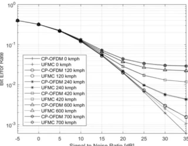
From Figure 6, it is evident that the UFMC, or as it is known UF-OFDM, outperforms the CP-OFDM, where the long tail of the latter extends to longer frequencies, making it not the promising candidate for short messages in the MMTC systems. The scope of this paper is to compare the user equipment velocity effects on both systems, CP-OFDM and UFMC. That is, Figure 7 validates the signal-to-noise ratio (SNR) and bit-error-rate (BER) performance in different velocities, where the baseband modulation order (mapping to constellation points) was 4-QAM. It is clearly shown that the BER performance of CP-OFDM in low speed degraded more than UFMC, where the latter does not employ CP, specifically at 0 kmph, 120 kmph and 240 kmph.
Figure 7.BER performance comparisons of CP-OFDM and UFMC. The velocity varies from 0 kmph to 700 kmph, the modulation order employed in this scenario was 4-QAM.
Figure 8.BER performance comparisons of CP-OFDM and UFMC. The velocity varies from 0 kmph to 700 kmph, the modulation order employed in this scenario was 16-QAM. It is a special case for low mapping order, which shows even at high speeds, 600 kmph, there is an improvement in the BER performance if the UFMC is employed as a modulation and access scheme. Increasing the velocity further reveals that the BER performance of both
systems differs slightly, or we can say the negligible difference.
Figure 8 depicts the same scenario as in Figure 7 but the modulation order in Figure 8 is 16-QAM. Because of the decreased distance between the constellation points, the improvement is only at zero kmph. The same attitude for higher modulation orders, 64-QAM and 256-QAM, can be seen in Figure 9 and Figure 10, where at zero kmph the UFMC outperforms the CP-OFDM.
Figure 9.BER performance comparisons of CP-OFDM and UFMC. The velocity varies from 0 kmph to 700 kmph, the modulation order employed in this scenario was 64-QAM
Figure 10.BER performance comparisons of CP-OFDM and UFMC. The velocity varies from 0 kmph to 700 kmph, the modulation order employed in this scenario was 256-QAM On the other hand, the throughput has different scenarios. Since the UFMC did not employ CP or overhead signal, the achievable throughput can be higher in UFMC than in CP-OFDM. As long as the SNR increases, of course, the throughput enhances significantly at any modulation order. For instance, Figure 11 shows the throughput enhancement for three velocity values, 0 kmph, 180 kmph, and 600 kmph. In Figure 11, as long as the velocity increases, the achieved throughput decreases. For instance, for
the first velocity, 0 kmph, the throughput of both systems, CP-OFDM and UF-OFDM, almost matches each other at -10 dB SNR, but the improvement becomes obvious as the SNR increases, for example, at SNR = 10 dB with velocity = 0 kmph, the throughput of the UF-OFDM outperforms the CP-UF-OFDM by 0.97 Mbit/s and at SNR = 30 dB, the throughput of the UF-OFDM increases from 19.9 Mbit/s to 23.5 Mbit/s, for the CP-OFDM and UF-OFDM, respectively. At user equipment velocity of 180 kmph and SNR = 0 dB, the UF-OFDM outperforms the CP-OFDM by 0.73 Mbit/s, while at 30 dB, UF-OFDM outperforms CP-OFDM by 4.2 Mbit/s. The 5G systems should support higher velocities, as shown in Figure 11.
At higher speeds, 600 kmph, the UF-OFDM has achieved higher throughputs, for instance, at -5 dB with velocity = 600 kmph, although the outperformance is small but we have to remember that this is 600 kmph velocity. At SNR = 20 dB, the UF-OFDM achieved throughput of 16.3 Mbit/s, while CP-OFDM achieved 13 Mbit/s. However, higher mobility speeds require very complicated circuitry to overcome the carrier frequency offset effects on the traditional CP-OFDM, while UF-OFDM requires less complexity [30].
Figure 11.BER performance comparisons of CP-OFDM and UFMC. The velocity varies from 0 kmph to 600 kmph, the modulation order employed in this scenario was 256-QAM
VII. C
ONCLUSIONFifth generation systems require improved physical layer air-interface than the traditional CP-OFDM employed in 4G. The new air-interface should provide the capability for short messages used between machines, that is, the UF-OFDM has been proposed. UF-UF-OFDM, as proved in this work, has the capacity for higher data rates, throughputs, and supports short message communications, thus, UF-OFDM can be used as a promising candidate for the next generation of
communication systems. Furthermore, it is shown that the UF-OFDM has enhanced capability in higher velocities than the traditional CP-OFDM.
VIII. A
CKNOWLEDGMENTSThe author would like to thank the staff of the Space Navigation and Control Laboratory of Department of Communications Engineering for the helpful suggestions and to provide the necessary simulators and computers to conduct the simulations.