Charged Particle Dynamics
of Negative-ion-rich Plasma in the Negative
Hydrogen Ion Source for NBI
Shaofei GENG
Doctor of Philosophy
Department of Fusion Science
School of Physical Sciences
SOKENDAI (The Graduate University for
Advanced Studies)
SOKENDAI
(The Graduate University for Advanced Studies)
Charged Particle Dynamics
of Negative-ion-rich Plasma in the
Negative Hydrogen Ion Source for NBI
Shaofei GENG
Doctor of Philosophy
2016
Contents
Abstract ... 1
1. Introduction ... 7
1.1 Global energy issues and fusion reactor ... 7
1.2 Neutral beam injection ... 11
1.3 Basis of negative hydrogen ion source ... 19
1.3.1 Volume process ... 20
1.3.2 Surface process ... 26
1.3.3 A brief review of the negative ion sources used for NBI systems ... 30
1.4 Objective of present work ... 31
1.5 Structure of thesis ... 32
References ... 34
2. Configuration of the negative ion source and diagnostics ... 38
2.1 Introduction ... 38
2.2 Configuration of the ion source ... 39
2.3 Single Langmuir probe ... 45
2.3.1 Electron and positive ion saturation currents ... 48
2.3.2 Plasma potential ... 50
2.3.3 Floating potential ... 50
2.3.4 Electron temperature ... 50
2.3.5 Electron density ... 51
2.4 Cavity ring-down ... 51
2.5 Laser photodetachment ... 55
2.5.1 Configuration of laser photodetachment ... 55
2.5.2 Wavelength of the laser ... 57
2.5.3 Energy density of the laser pulse ... 57
2.5.4 Voltage of the probe ... 58
2.5.5 Diameter of the laser beam ... 59
2.5.6 H- density ... 60
2.6 Summary ... 63
References ... 64
3. Characteristics of the plasma in the extraction region ... 65
3.1 Normal and negative-ion-rich plasma ... 65
3.2 Cs effect ... 66
3.3 Effect of controlling parameters ... 70
3.3.1 Dependence on bias voltage of the plasma grid ... 70
3.3.2 Dependence on hydrogen pressure ... 73
3.4 Spatial profile ... 75
3.4.1 Profile along the filter field in extraction region ... 75
3.4.2 Profile near an extraction aperture ... 79
3.5 Plasma profile perpendicular to plasma grid and response to extraction field . 82 3.6 Summary ... 87
References ... 90
4. Electron and positive ion flows ... 91
4.1 Directional Langmuir probe ... 91
4.2 Identification of electron and positive ion flows ... 93
4.2.1 Flow direction ... 93
4.2.2 Flow speed ... 96
4.3 Electron and positive ion flow in pure hydrogen plasma ... 97
4.3.1 Flow direction ... 97
4.3.2 Flow speed ... 103
4.4 Two-dimensional flow pattern ... 106
4.5 Summary ... 111
References ... 113
5. H- ion flow ... 115
5.1 Possible extraction mechanisms for the extraction of H- ions ... 115
5.2 Identification of H- ion flow ... 118
5.2.1 Recovery time ... 118
5.2.2 Recovery speed ... 119
5.2.3 Alignment of laser beam and probe tip ... 120
5.2.4 Determination of H- flow and temperature ... 121
5.3 H- flow and temperature ... 123
5.4 Production and extraction of H- ions ... 125
5.4.1 Flow pattern of H- ions ... 125
5.4.2 Production of H- ions ... 127
5.4.3 Extraction of H- ions ... 129
5.4.4 Stagnation point of H- flow ... 129
5.5 Summary ... 131
References ... 133
6. Conclusions and outlook ... 134
List of figures ... 140
List of tables ... 146
Published papers and conference presentations ... 147
Acknowledgements ... 150
1
Abstract
Neutral beam injection (NBI) is an effective method for plasma heating and current drive for fusion devices. In a neutral beam injector, charged particles are produced in the ion source, accelerated, neutralized and injected into the target plasmas confined in the fusion machine. Having the advantages of high neutralization efficiency, negative-ion- based Neutral Beam Injector (N-NBI) has been intensively developed to inject the beam with sufficient penetration length in the fusion plasmas. As the source of negative ions, the negative ion source determines the performance of the N-NBI system. Comparing to positive ion sources, negative ion sources have some differences, which are (1) the negative ones involve strong magnetic field to magnetize electrons in the source, (2) the source plasma consists of electrons, positive and negative ions, and (3) a part of electrons are extracted together with negative ions. In order to understand the mechanisms of electron and positive ion flow during beam extraction and the extraction of negative ions in Cs-seeded plasmas for the improvement of the present negative hydrogen ion source, investigation on charged particle dynamics of the negative-ion-rich plasma has been conducted. In this research, Langmuir probe, cavity ring-down, photodetachment, and four-pin directional Langmuir probe have been utilized for the experiments on the negative hydrogen ion source to investigate the characteristics of the negative-ion-rich plasma and the charged particle flows.
In Chapter 1, the worldwide energy issue and the importance of the development of magnetic confinement fusion was introduced. A neutral beam injector can inject high energy particles into a fusion device to heat the target plasma and drive plasma current. Having the advantages of high neutralization efficiency and low beam divergence angle, the N-NBI system is a preferable choice. The basis of negative hydrogen ion source has been introduced in this Chapter. In a negative hydrogen ion source, negative ions (H-) are produced by two mechanisms: (1) volume production and (2) surface production. In a practical negative ion source, Cs vapor is seeded and H- ions are mainly produced by
2
the mechanism of surface production. At National Institute for Fusion Science (NIFS), remarkable results have been achieved. The injection energy reached 190 keV and the total injection power was kept more than 15 MW. Research on improvements of the negative ion source is still necessary to obtain the stable and high power beam injections. In the R&D Negative Hydrogen Ion Source (NIFS-RNIS), negative-ion-rich plasma, of which electron density is one to two orders lower than that of H- ion, has been observed in the beam extraction region. During beam extraction, H- ion density decreases due to the extraction and electrons flow to the extraction region together with positive ions. Consequently, negative-ion-rich plasma is contaminated with electrons, and the co- extracted electron current is increased. The co-extracted electrons are filtered from the beam and absorbed onto the extraction grid. Increment of co-extracted electron current carries more heat load to the extraction grid and causes damages in high power and long pulse beam acceleration. Understanding of the mechanisms of the electron and positive ion flow in the extraction region and H- extraction is required for the improvement of the negative hydrogen ion source.
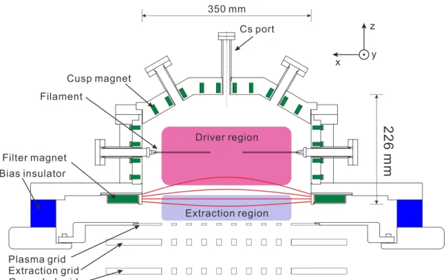
In Chapter 2, the negative ion source RNIS utilized for the experiments was introduced and described, as well as the diagnostic methods. This ion source is divided into a driver region and an extraction region by a transversal magnetic field named filter field. Plasma is generated by filament-arc discharge and confined in the multi-cusp magnetic field. Diagnostic tools including Langmuir probe, cavity ring-down and photodetachment technique have been applied to the experiments. Langmuir probe provided basic plasma parameters, for example, plasma potential Vs, electron density ne, electron temperature Te and so on. Although line-averaged H- ion density has been accurately obtained by cavity ring-down, H- ion density at a specific point is necessary for this research. For this purpose, photodetachment technique has been applied to the experiments. H- ion density nH- is proportional to the photodetachment current and a coefficient is required to evaluate nH-. In the conventional photodetachment method for electron-rich plasma, the coefficient is determined by the ratio of photodetachment current to electron saturation current of the probe. However, this method is not available in negative-ion-rich plasma. Then a new method based on the combination of cavity ring-down and photodetachment has been developed to determine the coefficient for the
3
estimation of nH-. This is the first time that nH- at a specific point is measured in a Cs- seeded negative ion source. In principle, this new method has no limitation of plasma condition.
In Chapter 3, the basic characteristics of the RNIS have been investigated by the diagnostics tools introduced in Chapter 2. The negative ion source requires long Cs- conditioning time because of the complicated and slow Cs expansion. After seeding Cs into the plasma, the plasma potential Vs decreases due to the emission of H- ions from the plasma-grid surface. The density of surface-produced H- ions increases comparable to electron density ne, which decreases as increasing nH- during Cs-seeding. The electron density ne is sensitive to the bias voltage applied to the plasma grid with respect to the plasma chamber, and ne decreases at higher bias voltage. nH- in the extraction region is lower at higher bias voltage of the plasma grid. It is necessary to apply low bias voltage to the plasma grid to obtain high H- beam current with the premise of avoiding damage on the extraction grid. Hydrogen pressure also influences the plasma in the extraction region. In this experiments, nH- decreases at high pressure due to the mutual neutralization with positive ions, since the temperature of positive ions decreases at high pressure and the reaction rate of mutual neutralization increases. Therefore, extraction and acceleration currents decrease at higher pressure. Low operational gas pressure is beneficial to the negative ion source, because the stripping loss of H- ions due to collisions with neutral molecules and atoms is reduced. However, the discharge is unstable in extremely low gas pressure, because the plasma of the ion source is sustained by electrons impact ionization and the mean free paths of electrons are larger at lower pressure. In addition, electron percentage in the source plasma increases with respect to H- percentage in low gas pressure. Consequently, 0.2 to 0.4 Pa of hydrogen pressure is a proper choice for the operation of the negative ion source for NBI.
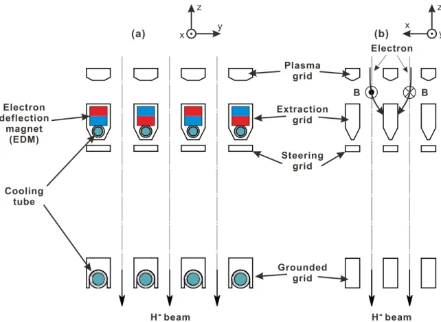
In the negative hydrogen ion source for NBI, an electron deflection magnetic field (EDM field) is introduced in the extraction gap to filter the co-extracted electrons. This EDM field forms a loop field by partially penetrating into the extraction region. The result of plasma profile measured with a Langmuir probe indicates that the boundary of
4
the EDM field is at ~10 mm apart from plasma grid. Electrons near the plasma grid are magnetized with the EDM field and trapped into the cusp region of the field.
The plasma response to extraction field has been investigated by scanning the measurement position of the Langmuir probe and photodetachment probe perpendicular to the plasma grid. By comparing the profiles of the probe saturation current and nH-
before and during beam extraction, the profile of the plasma response to the extraction region has been obtained. The results show that the maximum ne increase and nH-
decrement caused by the beam extraction is at ~20 mm apart from the plasma grid. The linear extrapolation of the profiles suggests the boundary of the extraction region and driver region of the ion source is at ~40 mm apart from the plasma grid. Although the maximum response is initially expected close to the extraction aperture, the experimental results show that the peak position of the plasma response is located far from the plasma grid.
In Chapter 4, flows of electrons and positive ions have been investigated by a four- pin directional Langmuir probe. The flow direction has been determined by the periodic distribution of the probe saturation current by rotating the directional Langmuir probe. The flow speed has been determined by the difference of probe saturation currents at upstream and downstream positions. The movement of electrons and positive ions are ambipolar. Flow changes of electron and positive ion have been observed by subtracting the two-dimensional flow patterns before and during beam extraction. By considering the flow pattern before beam extraction as a background and the transition of flow occurs is in a finite time, the change of the flow velocity is regarded as the flux increments of electrons and positive ions induced by beam extraction. The flux increments are from lower to upper side and trapped into the cusp region of the EDM field. The channel of the flux increments is at ~20 mm apart from the plasma grid and this region is the transition region of the filter field and the EDM field. Therefore, the probe located in this region can detect the maximum plasma response to the extraction field.
In Chapter 5, the four-pin directional Langmuir probe with photodetachment has been utilized to the experiments to investigate H- flow for the understanding of the extraction mechanism and the unexpected position of the maximum H- ion density reduction. The
5
flow velocity has been estimated using the recovery speed of the H- ion in the photodetachment region at upstream and downstream probe tips. Meanwhile, temperature of H- ions has been obtained. The result indicates that in the extraction region, temperature of H- ions is ~0.12 eV which is consistent with the result of saturated cavity ring-down measurement. The two-dimensional flow pattern of H- ions suggests that H- ions come from the direction of the plasma grid and flow to the extraction region. During beam extraction, H- flow turns to the aperture direction at ~20 mm apart from the plasma grid. Therefore, the maximum reduction of nH- can be detected near this position. In the extraction region, the Larmor radius of H- ion is ~10 mm. Note that the boundary of the EDM field is at ~10 mm apart from the plasma grid. These two dimensions elucidate the existence of stagnation point of the H- ions located at ~20 mm apart from the plasma grid.
In conclusion, it becomes clear that H- ions undergo following sequence from production to extraction by applying extraction field: (1) H- ions come from the direction of the metal part of the plasma grid, (2) once flow towards the plasma in the extraction region, (3) turn at the stagnation point located at ~20 mm apart from the plasma grid and (4) move to the aperture of the plasma grid. The behavior of the H- flow is affected by the EDM field and filter field. The region of the stagnation point corresponds to the transition region of the filter field and the EDM field. In this region, the extraction- induced additional electron and positive-ion fluxes increase and the stagnation point appears. Consequently, the maximum plasma response to the extraction field is far from the plasma grid. In addition, the H- ion temperature is estimated to be ~ 0.12 eV. This is one of the evidences that negative hydrogen ion beam has a low beam divergence angle. In the NIFS-RNIS, H- ions are not extracted directed from the surface of the plasma grid but mainly from the region near the aperture of the plasma grid.
Since the extraction process occurs in the region near the plasma-grid aperture, the improvement of the negative hydrogen ion source is possible to be focused to this region. One of the improved method is to increase the EDM field, and then boundary of the EDM field becomes far from the plasma grid. More H- ions will be extracted by increasing the magnetic region. Meanwhile, suppression of electrons near the plasma
6
grid is then enhanced. Consequently, the increase in the extracted H- ion current and decrease in electron component are possible. The performance of the negative ion source is expected to improve.
7
1. Introduction
1.1 Global energy issues and fusion reactor
A fundamental characteristic of modern industrial society is the consumption of large amount of energy. The production and development are driven by the use of technology which depends on the external energy source in the industrial society [1]. The use of large amount of energy is also essential for food production due to the mechanization of agriculture. The required human labor decreases as the increasing efficiency and the excess labor is moved to the urban and participates in the industrial production or service industries. The urban is supported by the input of external energy for the activities of production, daily life, transportation, storage, and so on [2]. Consequently, the growth of modern industrial society is correlated with the energy consumption. Figure 1-1 shows the correlation of energy use and gross domestic product (GDP) around the world in 2012. It is apparent that the countries having higher GDP per capita consumed more energy.
During the first industrial revolution, coal became the main source of energy in the production activities. In the past decades, fossil fuel including oil, coal, and natural gas so on, captured around 80% of the energy consumption for human beings as illustrated in Figure 1-2. The heavy used of the fossil fuel caused serious environment issues. Most of the greenhouse gas emissions come from the combustion of fossil fuels which also produces pollution to the air due to the emissions of SO2, NOx, and heavy metals. As a consequence, acid rain is produced and falls to the Earth causing influence to the natural. In addition, the polluted air can also lead to respiratory diseases because the particles of the emissions can induce negative effects to the health when inhaled by people.
Presently, the fossil fuel supports the source of the energy mainly. Unfortunately, the amount of fossil fuel is limited and cannot be reproduced. Figure 1-3 shows the so called
"peak oil" theory [3] which indicates the point of the maximum production of petroleum.
8
After the peak oil point, the rate of production of petroleum is expected to enter terminal decline and people have to face to the shortage of energy for the daily life and the growth of industry. This brings a demand to find an alternative energy source for the future.
Figure 1-1. Annual energy consumption versus annual GDP per capita. (Data source: World Bank Group, 2012)
Figure 1-2. Fossil fuel energy consumption. Fossil fuel comprises coal, oil, petroleum, and natural gas products. (Data source: World Bank Group, 2012)
9
Figure 1-3. Oil and gas production profile [3].
Even renewable energy which comes from the resources can be naturally replenished, such as solar energy, wind, tides, and geothermal heat etc. have been widely developed, its efficiency is limited and the stability is influenced by the circumstance. Actually, these energy resources fluctuate time by time and the deviation exceeds the acceptance of the industrial usage of electricity. Nuclear power plants based on nuclear fission seems a good choice because of the low fuel consumption. However, people have to consider the risk of accidents and incidents of nuclear power plants. Additionally, disposal of the nuclear waste, including high-level, intermediate-level, and low-level waste, is a critical issue since people have to develop technology to seal the radionuclide safely and find appropriate permanent sites which is still under way in some countries [4].
Without the disadvantages of the emissions of greenhouse and toxic gases, particulates and inducing environmental disaster due to accidents, a nuclear fusion reactor is considered as an excellent alternative to fossil fuel and fission reactor. In a fusion reactor, nuclear fusion reactions occur when two atomic nuclei come close enough and then collide to form a new nucleus since the strong nuclear force which pulls the two nuclei together exceeds the Coulomb’s force which pushes them away. Large amount of energy is released during this process. Nuclear fusion is the mechanism of energy production in a star [5].
10
For a fusion reactor used for a power plant, the fuel is limited to the lightest element which is the easiest atom to ignite because of the small charge. The isotopes of hydrogen, deuterium (D) and tritium (T) are selected as the fuel for a fusion reactor. The process of the fusion of deuterium and tritium is
D + T → 4He (3.5 MeV) + n (14.1 MeV). (1-1) Deuterium is a stable isotope of hydrogen and can be extracted from seawater. Tritium is not stable and quite rare in nature. It can be produced inside the fusion reactor from the breeding blanket when energetic neutrons impact the lithium of the blanket:
n + 6Li → T + 4He +4.8 MeV, (1-2)
n + 7Li → T + 4He + n - 2.5 MeV. (1-3)
The reaction cross section is an evaluation of the fusion reaction probability which depends on the relative velocity of the two colliding nuclei. Usually, the nuclei have a velocity distribution. Therefore, an average over the distributions of cross section and velocity, < v>, which is called “reactivity”, is used to evaluate the reaction rate. Figure 1-4 indicates that for D-T reaction, high temperature is necessary since the reactivity decreases rapidly when the temperature is lower than 20 keV. At the temperature required according to Figure 1-4, the fuel deuterium and tritium exist in plasma state.
Huge amount of supply of power is required to the fusion reactor to produce and maintain the deuterium and tritium plasma. In order to realize net output of energy from a fusion reactor, the heating of the plasma by fusion reaction is required to be sufficient to maintain the temperature of the plasma and to compensate the power losses from the plasma, and then a steady state can be obtained. The condition to obtain such steady state of plasma is called “Lawson criterion”. Since the produced heating by fusion reaction can sustain the plasma temperature against the energy losses, the applied external heating can be removed and the plasma is maintained by internal heating. The Lawson criterion is the condition for starting burning plasma. It suggests a minimum requirement on the product of plasma (electron) density ne, confinement time E, and plasma temperature Tpl. For D-T reaction, the requirement for starting burning plasma is
ne Tpl E > 3 × 10²¹ m-3 keV s. (1-4)
11
The minimum value of the product neTpl E appears when the plasma temperature is close to 14 keV [6]. It is essential to heat up the plasma in a fusion reactor above the ignition temperature.
Figure 1-4. Fusion reaction rate between light atoms [5].
1.2 Neutral beam injection
There are several means to heat up the plasma in a fusion reactor including ohmic heating, electron cyclotron resonance heating (ECRH), ion cyclotron resonance heating
12
(ICRH), and neutral beam injection (NBI) heating. The theme of this thesis focuses on the neutral beam injection (NBI). Only NBI will be introduced.
The fundamental concept of NBI is the injection of a high-energy beam of neutral atoms, typically hydrogen or deuterium into the plasma in the fusion reactor. The atoms in the high-energy beam transfer their energy to the plasma, and then the plasma is heated up and temperature increases.
By injecting high-energy neutral beam into the plasma in a fusion reactor, a neutral beam injector is possible to be applied for several purposes. They are summarized as followings:
(1) Plasma heating [7,8]
In order to realize the plasma temperature higher than 10 keV for ignition, neutral beam injection heating is one of the approaches. The energetic neutral atoms injected into the plasma from a neutral beam injector are ionized by electron-impact ionization, ion-impact ionization, and charge exchange, and then captured by the magnetic field of the fusion reactor. The energetic ions converted from the neutral atoms transfer their energy to electrons and ions by collisions. The temperature of plasma increases, consequently.
Plasma heating by NBI has archived remarkable results for fusion reactor research. For instance, fusion power of 16 MW has been produced at 22.3 MW of input NBI power on the Joint European Torus (JET) [9].
(2) Current drive [10,11]
On a Tokamak-type fusion reactor, plasma current is important for the confinement of the plasma. It is difficult to produce the plasma current continuously by the transformer via the change of magnetic flux for long time. Neutral beam injection acts as one of the effective methods for non-inductive current drive for the steady operation of a Tokamak- type fusion reactor.
(3) Fuelling [8]
13
In addition to the injection of gas puffing and pellets injection to increase the plasma density, neutral beam injection is also a desirable method to fuel the fusion reactor. The particle flux from NBI can be expressed as
Nf = 6.25 × 10²¹ P/Ef, (1-5)
where the Nf is the particle flux, P is the injection power in MW, and Ef is the injection energy in keV.
Particles from NBI can fuel the central plasma due to their high energy. This is essential to control the central plasma density.
(4) Plasma diagnostics [12-15]
Neutral beam injection can also be applied for the diagnostics of the plasma to measure several plasma parameters such as ion temperature, density of impurities, plasma current density profile, and plasma rotation speed etc. by Doppler effect, Stark effect, and charge exchange recombination spectroscopy (CXRS) after the high energy beam is injected into the plasma.
Figure 1-5. Conceptual illustration of a neutral beam injector.
14
Conceptual view of neutral beam injector is schematically shown in Figure 1-5. At the head part of the neutral beam injector, the left most part of the Figure 1-5, a device producing low temperature plasma is installed, from which, ions are generated and extracted. This device gives the name “ion source”. Ions produced in the ion source are extracted by so-called extraction and acceleration grid system which is also known as
“beam optical system”. Ions are accelerated by the electrostatic field of the acceleration grids and focused to form an ion beam. The ion beam then enters the neutralization cell and the ions collide with the background gas, experience charge exchange for positive ions or electron stripping for negative ions. A part of the ions are neutralized during this process and a neutral beam is formed. The remaining ions which are not neutralized and the positive ions via re-ionization process are then deflected by a magnetic field, and absorbed by a residual ion beam dump. Since the neutralized particles are not influenced by the magnetic field and can pass through the magnetic field directly, the neutral beam is injected into the fusion reactor.
In a fusion reactor, the injected neutral particles experience collision with the background plasma and lose energy during this process. The penetration depth of the neutral beam L depends on the initial energy of the neutral beam and the density of the background plasma:
L = (E/A)/18ne, (1-6)
where the unit of L is meter, E is the energy of the neutral beam in keV, A is the mass of the injected neutral particle in amu, and ne is the plasma density in 1019m-3. In order to heat the central plasma, high energy neutral beam is desirable.
The neutralization of the accelerated ion beam happens in the neutralization cell of the NBI system by the collisions of ions with background gas and neutralization efficiency is determined by the collision cross sections. For deuteron and proton (D+/H+) the maximum neutralization efficiency drops down steepy as the beam energy is higher than 100 keV and decreases to be lower than 20% at 200 keV of beam energy. This brings a serious issue to the overall efficiency of the NBI system and a decrease to the output power. In addition, the remaining ions which are not neutralized in the NBI system causes amount of heat load to the beam. On the other hand, the neutralization
15
efficiency of negative deuterium / hydrogen ions (D-/H-) can keep higher than 60% even the beam energy reaches 1 MeV as shown in Figure 1-6 [16,17]. Having this advantage, the negative ion based NBI system (N-NBI) is a desirable device to obtain high energy beam.
Figure 1-6. Maximum neutralization efficiency of D- and D+ beam versus beam energy [16].
In addition to the neutralization efficiency, the N-NBI system has advantage in beam divergence. For a Tokamak, dense toroidal coils are necessary in order to generate strong toroidal magnetic field, and then the space for an injection port is limited because the injection port can only be in the gap between two neighbor coils. For a stellarator, the coil structure is complicated in order to generate proper helical magnetic field. A challenge of the injection port design also exists due to the limited space. For a practical fusion reactor, for example DEMO (DEMOnstration Power Plant), D-T reactions happen in the reactor and large number of neutrons is produced. The vessel of the fusion reactor has components for shielding the neutrons. However, the NBI injection port is a leakage window for neutrons. The neutron flux can travel to the outside of the fusion reactor through the injection port. Consequently, an injection port with dimension as small as possible is appropriate. The requirement of small injection port introduces the demand of neutral beam with small divergence.
16
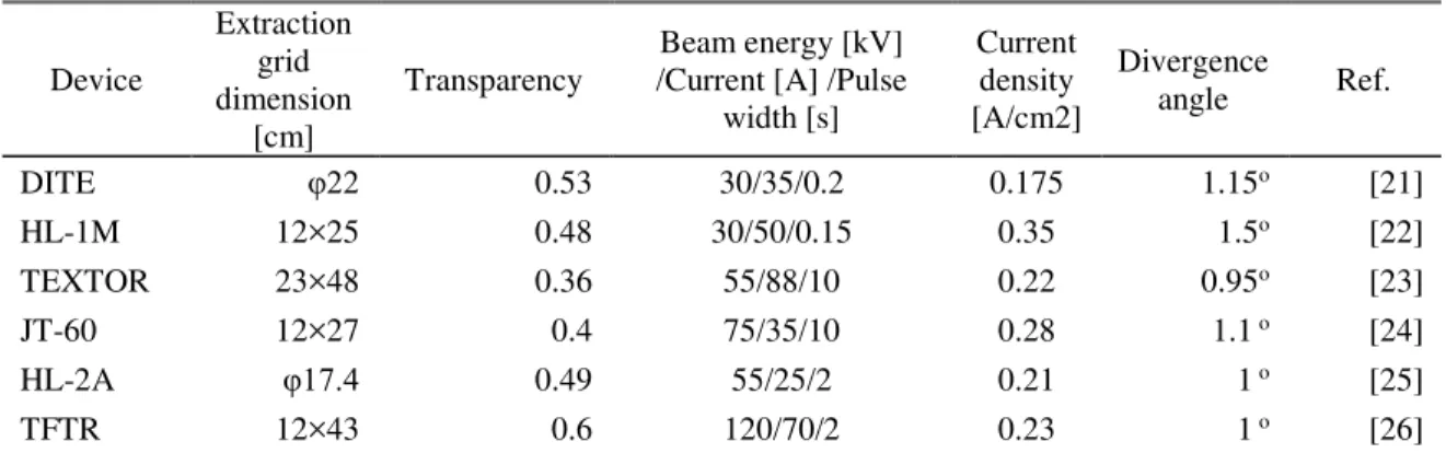
Under the condition of well designed beam optics system, the minimum beam divergence is influenced by the ion temperature and space charge mainly. The ion temperature introduces a transverse speed in to the particles in the beam. During beam transport, the beam can also expand due to the repulsive force caused by space charge. In an positive ion source based on filament-arc discharge, the ion temperature is around 1 eV [18]. Coupland et al. has calculated the ion temperature which reaches 7 eV in a helium ion source [19]. On the other hand, the negative ion temperature in a negative hydrogen ion source is one order lower than the positive ion temperature [20]. Table 1-1 shows the beam parameters of positive NBI system on some devices. It can be found that the divergence angle of the ion beam extracted from positive ion sources is around 1o. This value is consistent with the statement that under “perveance match” condition, 80% of the ion beam current extracted from a positive ion source can be found within a divergence angle of less than ±1.15o [18].
Table 1-1. Beam parameters of positive NBI system on some devices.
Device
Extraction grid dimension
[cm]
Transparency
Beam energy [kV] /Current [A] /Pulse
width [s]
Current density [A/cm2]
Divergence
angle Ref.
DITE φ22 0.53 30/35/0.2 0.175 1.15o [21]
HL-1M 12×25 0.48 30/50/0.15 0.35 1.5o [22]
TEXTOR 23×48 0.36 55/88/10 0.22 0.95o [23]
JT-60 12×27 0.4 75/35/10 0.28 1.1 o [24]
HL-2A φ17.4 0.49 55/25/2 0.21 1 o [25]
TFTR 12×43 0.6 120/70/2 0.23 1 o [26]
On the Large Helical Device (LHD) at the National Institute for Fusion Science (NIFS), both positive and negative NBI systems are equipped. The beam divergence of the positive ion beam is 1.1o. On the other hand, the ion beam divergence angle of the N- NBI system is less than 0.29o [27]. The small divergence angle of the negative ion beam is not only because of the low negative ion temperature, but also attributed to the low current density. From Table 1-1, it can be found that the typical positive ion beam current density is around 200 mA/cm2. The current density of a negative ion beam extracted from a negative ion source for N-NBI is around 30 mA/cm2 [27]. Therefore,
17
the space charge effect of negative ion beam is one order lower than that of positive ion beam. The divergence of the negative ion beam due to space charge is lower.
Owning to the low divergence angle of negative ion beam, it is possible to design the long beam path for the beam line, and this is beneficial to reduce neutron flux and of magnetic strength from torus.
Figure 1-7. Beam line configuration of LHD
The N-NBI system has been used in LHD [28] and JT-60U [29] due to its advantages in neutralization efficiency at the beam energy more than 100 keV and beam divergence. It will also play an essential role in plasma heating and current drive for ITER [30]. The N-NBI systems have contributed remarkable achievements for LHD. As shown in Figure 1-7, LHD is equipped with 5 beam lines (BL). Beam lines 1, 2 and 3 are N-NBI and BL 4 and 5 are positive ion-based NBI (P-NBI). Two negative ion sourced are installed on each beam line. By optimizing caesium (Cs) dose rate and beam control, the injection power by the three N-NBI beam lines has reached and kept 15 MW as shown in Figure
18
1-8. The injection power and H- ion current density are presented in Figure 1-9. The maximum injection power per beam line has reached 6.9 MW and the current density of H- ions has achieved 340 A/m2 which exceeded ITER NBI requirement on beam current density.
Figure 1-8. Total injection power of N-NBI systems on LHD
At Japan Atomic Energy Agency (JAEA), an arc-driven negative ion source was applied for the NBI beam line of JT-60SA. The beam energy reached 0.5 MeV. The maximum beam current depended on the beam duration which was 32 A at 1 s of beam duration and decreased to 15 A at 100 s of beam duration. Correspondingly, the beam current was 189 A/m2 and 89 A/m2 at 1 s and 100 s of beam duration, respectively. The maximum beam duration was 100 s [31].
Figure 1-9. Injection power (a) and current density (b) of LHD-NBI per beam line
(a) (b)
19
1.3 Basis of negative hydrogen ion source
The early application of H- ions was to double the particle energy in a DC particle accelerator, which is called “tandem accelerator”. According to this concept, an H- ion is accelerated from ground (0 V) to high positive potential (+V) which is sustained by an electrode. At the electrode, incoming H- ions are converted to protons through thin film by stripping two electrons. The protons are accelerated from high positive potential (+V) to ground (0 V). Finally, a beam with energy which is twice of applied DC voltage on the acceleration electrode can be obtained [32]. The schematic illustration of this concept is shown in Figure 1-10.
Figure 1-10. Schematic illustration of energy doubling in a DC accelerator
The advantages of using negative ions in an accelerator are not only to double the final energy of the particles. In a cyclotron, because H- ions are converted to protons, the Lorentz force applied to the particles changes its direction. As a consequence, the extraction of the accelerated beam becomes much simpler [33]. Over the past decades, a variety of negative ion sources have been applied to many accelerators for various purposes [34]. The research of negative hydrogen ion source oriented to NBI systems of fusion reactors started from 1970s. So far, the negative-ion-based NBI system has become indispensable equipment for the advanced fusion reactor.
Of course, a question listed at the top is how to produce H- ions in a negative ion source. The H- ion production mechanisms can be classified to two types: (1) volume process and (2) surface process.
20
1.3.1 Volume process
Figure 1-11. Schematic illustration of potential energy curve for H2 and H2-
In pure hydrogen plasma, H- ions are produced mainly though the process of dissociative attachment (DA) of electrons to vibrationally excited H2 molecules. Experimental investigations have been conducted by G. J. Schulz and D. Rapp in order to measure the cross section of DA in the process of electron colliding with vibrationally excited H2 molecules in 1s-1s state at low electron energy [35,36]. In this process, an electron is temporarily captured to the H2 molecule and an intermediate H2- state is formed. The lifetime of this H2- state is only ~10-15 s and then a decay process occurs with production of a neutral hydrogen atom and a negative hydrogen ion as described as following,
1 ) e H ( ) H H
(
H2 X1 g s 2 X e 2 u . (1-7)
This process is schematically demonstrated in Figure 1-11. The cross section for the reaction has a maximum value 1.6 × 10⁻²¹ cm2 or 2.8 × 10⁻²¹ cm2 (depending on the choice of the data) [37] at electron energy of 3.75 eV which is the threshold energy for the formation of H- ions, since at incident electron energy lower than 3.75 eV, the reverse
21
auto-detachment is very possible and compound system can decay to the ground or a higher vibrational state by emitting an electron [36].
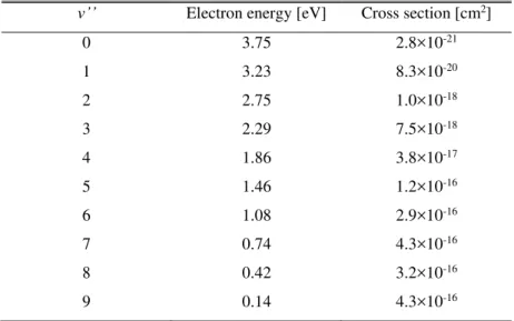
In 1979, a drastic increase of the DA cross sections have been found theoretically and experimentally when H2 molecules are in either vibrationally or rotationally excited states [38,39]. An impressive phenomenon is that the cross sections increase by four orders of magnitude for excited H2 molecules from the vibrationally excited state v’’ = 0 to v’’ = 4. Table 1-2 shows the cross sections of DA process for H2 molecules in vibrationally excited states v’’ = 0 to v’’ = 9 calculated by Wadehra [38].
Table 1-2. Dissociative attachment cross sections near thresholds for H2 molecules at vibratinally excited states v’’ = 0 to v’’ = 9 [38].
v’’ Electron energy [eV] Cross section [cm2]
0 3.75 2.8×10⁻²¹
1 3.23 8.3×10⁻²⁰
2 2.75 1.0×10⁻¹⁸
3 2.29 7.5×10⁻¹⁸
4 1.86 3.8×10⁻¹⁷
5 1.46 1.2×10⁻¹⁶
6 1.08 2.9×10⁻¹⁶
7 0.74 4.3×10⁻¹⁶
8 0.42 3.2×10⁻¹⁶
9 0.14 4.3×10⁻¹⁶
Since the cross sections for DA process are enhanced much if H2 molecules are in vibrationally or rotationally excited states, the main mechanism to produce H- ions in pure hydrogen plasma can be considered as the process of dissociative attachment of electrons to excited H2 molecules. This is a two-step process [40] : (1), Production of vibrationally and rotationally excited H2 molecules H2*(v’’) and (2), Formation of H- ions by dissociatively attaching low energy electrons to H2*(v’’) molecules, as described as follows:
e ) ( H e
H2 *2 v'' , (1-8)
H H e ) (
H*2 v'' . (1-9)
22
In Allan’s experiments, the dependence of vibrationally excited states of H2
molecules on electron energy has been investigated [39]. If electron energy is lower than 5 eV, H2 molecules at ground electronic state are excited to vibrational states up to v’’ = 4 by the collisions between electrons and H2 molecules. The formation of H- ions in this process is
e ) ' ' ' ' , 1 ( H ) eV 5 ( e ) ' ' , 1 (
H2 X1g s v *2 X1g s v v , (1-10) H
H 1eV) e( ) ' ' , 1 (
H*2 X1g s v . (1-11)
In 1979, Bacal has measured H- ion density using photodetachment technique in arc discharge plasmas. The result showed that the H- ion density reached as high as 30% of positive ion density at optimized arc condition and pressure [41]. The reactions described in Equation 1-10 and 1-11 were the main processes for the formation of H- ions [40,41] in this experiment. However, in Equation 1-10, the most possible value for Δv’’ is Δv’’ =
±1, and a higher vibrational state is difficult to reach [42]. In order to obtain the population of H2 molecules in higher vibrationally excited states, collisions of H2
molecules in ground vibrational state with energetic electrons are required. The processes for the formation of H- ions involving in energetic electrons are [42,43]
e ) , 2 ,
2 ( H ) eV 20 ( e ) 0 ' ' , 1 (
H2 X1g s v 2* B1u p C1u p , (1-12) hν
) ' ' , 1 ( H ) , 2 ,
2 (
H*2 B1u p C1u p 2* X1g s v , (1-13) H
H 1eV)
~ e( ) ' ' , 1 (
H*2 X1g s v . (1-14)
H2 molecules in ground electronic state are excited to high electronic states including all members of singlet electronic states (B, C …) as indicated by line 1 in Figure 1-12. The singlet states then decay to ground electronic state with a photon emission, but in higher vibrational states as indicated by line 2 in Figure 1-12. H- ions are then produced when low energy electrons are attached to the highly vibrationally excited H2 molecules. The cross section is large if electron energy is around 1 eV [38]. In a negative hydrogen ion source, H- ions produced through volume production mechanism are mainly generated from the H2 molecules in high vibrational states (v’’>4) [42]. The process in Equation 1-12 is effective if the electron energy is higher than 20 eV and the cross sections reach maxima at incident electron energy of about 40 eV [44].
23
Figure 1-12. Potential energy curves for H2 and H2- in different states.
According to the mechanism of volume process for producing H- ions, in order to obtain intense H- ions in the ion source, requirements can be summarized as follows briefly:
(1). Energetic electrons (20-40 eV) are necessary to obtain large cross sections to excite H2 molecules to high vibrational states.
(2). Low energy electrons (~1 eV) are necessary to obtain large cross sections for DA process of electrons to excited H2 molecules (v’’ > 4).
24
(3). Electron affinity of an H- ion is 0.754 eV. Electron with energy higher than 1 eV can destroy H- ion through the electron detachment (ED) process
e 2 H ) eV 1 ( e
H . (1-15)
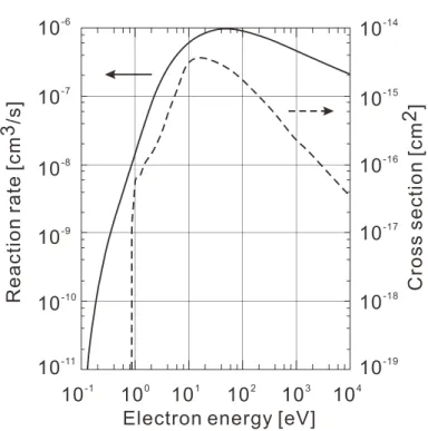
Figure 1-13. Cross section and reaction rate for ED process of H- ions vs. electron energy.
The cross section and reaction rate for ED process has been shown in Figure 1-13 [45]. The cross section increases drastically when the electron energy is higher than 1 eV. Therefore, it is necessary to keep the electron energy lower than 1 eV to minimize losses of H- ions.
A negative hydrogen ion source should have the ability of producing plasma with energetic electrons in order to maximize the production of excited H2 molecules (v’’ > 4). In addition, low energy electrons are required to reduce the destruction of H- ions. Satisfying these requirements, the concept of “tandem-type ion source” has been widely used by the negative hydrogen ion sources for NBI systems.
25
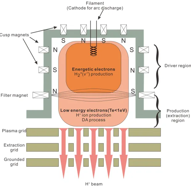
Figure 1-14. Schematic illustration of a volume production negative hydrogen ion source.
Figure 1-14 shows the schematic illustration of a “tandem-type” volume production negative hydrogen ion source. A typical characteristic of the ion source is the application of filter magnetic field which divides the ion source into a driver region and an extraction/production region. In the driver region, plasma is generated by filament-arc discharge. Primary electrons emitted from the hot filaments has energy high enough to excite H2 molecules to high vibrational states (v’’ > 4). The filter magnetic field plays a role of barrier for the primary electrons to prevent them from directly flowing from the driver region to the extraction/production region [30]. Energetic electrons are trapped into the filter magnetic field, diffuse across the filter field and experience collisions with
26
other particles. As a consequence, electrons lose their energy and are thermalized. Low temperature electrons (Te < 1 eV) can be obtained in the extraction/production region for the production of H- ions through DA process. H- ions are mainly concentrated in the extraction/production region in which the DA process is effective and losses of H- ions by ED reaction are minimized. Sufficient H- current can be obtained by volume process. However, H2 gas load is too high and not acceptable for practical N-NBI .
1.3.2 Surface process
Production of H- ions through so-called surface process is the main mechanism for the present negative hydrogen ion sources applied to NBI systems for fusion experimental devices. A significant improvement in the negative ion production has been achieved by seeding a small amount of Cs into the negative ion source [46]. This has been shown that the production of H- ions is dominated by surface processes on the wall of the negative ion source [47]. In the surface processes, H- ions are emitted from the metal surface with low work function in the process of (1), energetic hydrogen atoms (H) impacting with the wall and being bounced back to the plasma with capturing an additional electron and (2), positive ions (H+, H2+ and H3+) impacting with the wall and being emitted back as H- ions [18,48].
If an H atom has enough energy higher than the work function of the metal-wall surface, the yield of H- ions depends on the energy of incident atoms. Experiments by Lee and Seidl have shown that the maximum yield is as high as 25% for an H atom temperature of 5 eV with Cs covered Mo surface [49]. The dependence of H- ion yield on the energy of incident H atom is shown in Figure 1-15.
If the incident particles are enrgetic positive ions, the yield of H- ions is also denpends on the energy of the positive ions. Experiments by M. Seidl et al. have demostrated that a saturation in H- yield can be found for a Cs covered Mo surface with work function of 1.5 eV [50]. The threshold energy for the saturation is ~15 eV as shown in Figure 1-16.
27
Figure 1-15. Depenced of H- ion yeild on the energy per incident H atoms [49].
Figure 1-16. Dependence of H- ion yield on the incident energy per nucleus [50].
28
In order to produce H- ions the backscattered particles need to capture electrons from the atoms of the surface. The probabilty of H- ion production denpends on the work function of the metal surface and decrease with the increasing work function significantly [18]. However, the electron affinity of H- in interaction-free condition is only ~0.754 eV. On the other hand, the work function of refactory metals, such as tangsten and molybdenium, used in dense plasma exceeds 4 eV (for tungsten: 4.55 eV and for molybdenum: 4.6 eV) [43]. In order to produce H- ion effectively through surface process, it is essential to reduce the work function of the metal surface.
Generally, the work function of the metal surface can be decreased by covered with low work function materials such as alkaline earth atoms. The work function of the metal surface covered with alkaline atoms can be lower than the work function of the substrate. In all the potential materials, caesium (Cs) has the lowest work function which is only 2.1 eV. Therefore, Cs has been chosen for negative hydrogen ion sources applied for NBI systems.
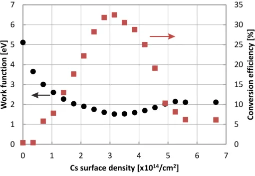
The work function of the metal surface depends on the Cs coverage. As shown in Figure 1-17, schematically, the work function of the Mo surface decreases with the increasing Cs coverage. The minimum work function appears at Cs coverage of 0.6 monolayes for the (110) face of a single Mo crystal. When the Cs coverage is higher than 1 monolayer, the work function is up to about 2.1 eV [18,51] and approaches to the work function of Cs metal. The behavior of work function dependence on the Cs coverage has been observed in the experiments [52] as shown in Figure 1-18. The work function of clean W (110) surface is measured as 5.1 eV and decreases initially toward the minimum value 1.45 eV with around half a monolayer Cs. Further Cs coverage increases the work function to 2.15 eV. The conversion efficiency of H+ ions to H- ions is also shown in Figure 1-18 Corresponding to the minimum work function, the maximum conversion efficiency can be found.
29
Figure 1-17. Dependence of work function of Cs covered Mo surface on the thickness of Cs layer.
Figure 1-18. Dependence of surface work function for the (110) face and H- ion conversion efficiency on the surface density of deposited Cs [52].
An optimum Cs condition exists due to the existence of minimum work function for the surface production of H- ions. It is possible to reach to the optimum Cs condition in a negative hydrogen ion source from the engineering point of view, because the ionic characteristic is partially included in the half a monolayer Cs on W and Mo metals. Due to the ionic characteristic, the binding energy between the Cs and those metals are much
30
stronger than the metallic bond of Cs-Cs. Overmuch Cs atoms on the metal surface can be sputtered into the chamber by the energetic particles in plasmas or evaporated by controlling the temperature of the metal surface.
1.3.3 A brief review of the negative ion sources used for NBI systems
In order to produce dense H- ions, regular hydrogen plasma should be generated in the ion source. In principle, all kinds of discharge producing large area plasma can be used, including:
(1), Arc discharge
(2), Radio frequency (RF) discharge
(3), Electron cyclotron resonance (ECR) discharge (4), Magnetron glow discharge
(5), Microwave discharge
Various kinds of negative ion sources have been developed for NBI systems. In a charge exchange ion source, it has been reported that by using a 1.5 keV 200 mA D+ ion beam which is extracted from a multi-aperture ion source, passing through Cs vapor, a 50 mA D- beam has been obtained [53]. Because of the disadvantages of polluting the beam line by Cs vapor, large beam divergence angle and difficulty in matching with accelerator system, this type of ion source was not used since 1980s. The magnetron type negative ion source was historically the first negative ion source. The H- ion current increased from several milliampere to 880 mA by seeding Cs into the ion source [54,55]. In 1980s, a type of multicusp surface production ion source has been developed [56]. This ion source has been improved by replacing the Cs-coated copper surface by a pure Ba surface at the end of 1980s [57]. The developments of volume production negative ion sources were accelerated after the enhancement of DA process of electrons to the high vibrationally exited H2 molecules was found [39,41] and the application of filter
31
magnetic field [58]. In 1990, a 3.4 A H- ion beam was obtained in the volume production negative ion source at JAEA with H2 pressure of 2.1 Pa [59]. However, this ion source was not enough for a NBI system since the high operational pressure and low H- ion current density which was 13 mA/cm2. The performance of this type of ion source has been increased significantly by seeding a small amount of Cs in to the ion source following the experiments of Leung [60].
With the considerations of high power (several ten kilowatts), stability of the plasma and robustness of the ion source, only arc-discharge-driven and RF-discharge-driven ion source have been used for NBI systems in present. So far, 34 mA/cm2 H- ion beams have been achieved in the arc-discharge-driven ion source for LHD-NBI at NIFS. At JAEA, the H- ion beam extracted from an arc-discharge-driven ion source reached 18.9 mA/cm2. In IPP Garching, an RF-driven negative ion source has been developed oriented to the application of NBI systems of ITER. The H- ion current density has reached 35 mA/cm2 with 4 s beam extraction [61].
1.4 Objective of present work
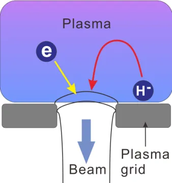
In a negative hydrogen ion source, electrons, H- ions and positive ions exist in the beam extraction region. By applying extraction voltage, both H- ions and electrons are extracted since H- ions and electrons have the same charge polarity. The extracted H- ions are the required particle for the beam used for N-NBI. On the other hand, the extracted electrons, named co-extracted electrons are unnecessary and have to be removed from the beam. A deflection magnetic field is applied to the extraction grid to suppress electrons near the plasma grid and deflect the co-extracted electrons [62]. The co-extracted electrons are mainly absorbed by the extraction grid. Consequently, the extraction grid has to suffer additional heat load bringing by the co-extracted electrons.
In the experiments on NIFS Research and Development Negative Ion Source (NIFS- RNIS), it has been observed that H- ion density decrease by applying extraction voltage and meanwhile electron density increase in the beam extraction region. This
32
phenomenon indicates that H- ions are partially replaced by the electrons flowing from the driver region during beam extraction [63]. Therefore, the ratio of H- ion density to electron density decreases. The ratio of accelerated current to the extraction current then also decreases. The efficiency of the negative ion source can be increased if the H- ion density is possible to be kept constant and additional incoming electrons are possible to be suppressed during beam extraction. The detailed transport dynamics in negative ion source is unknown and has not been measured yet. In order to know the mechanism, it is necessary to understand the magnetic structure in the beam extraction region, response of charged particles to electrostatic field, diffusion type of electron and positive ions and movements of electrons, positive and negative ions. The present work is an experimental study on the charged particle dynamics of the negative-ion-rich plasma in the extraction region, aiming at the understanding of the extraction process of H- ions. Some suggestions to increase the efficiency of the negative ion source are expected from results of this work.
1.5 Structure of thesis
The present work is organized in the following way in this thesis as illustrated in Figure 1-19. In chapter 2, NIFS-RNIS is introduced. The structure of the magnetic field, which plays an important role in plasma profile and plasma flow, is demonstrated and discussed. Diagnostic methods used for this work including Langmuir probe, photodetachment and cavity ring-down are briefly summarized. A new method to calculate the local absolute H- ion density is introduced in detail. In chapter 3, results obtained by the diagnostics introduced in chapter 2 are put forward. The conversion of normal plasma to negative-ion-rich plasma, the effect of Cs, the effect of external parameters, plasma profile and effect of extraction field are discussed. Basic characteristics of NIFS-RNIS are summarized. In order to measure the charged particle flow, methods of a directional Langmuir probe (DLP) and DLP with photodetachment are applied to the experiments. They are described in chapter 4. In this chapter, the one- dimensional charged particle flow is shown and discussed. Ambipolar movement and
33
drift dominate the flow. H- ion temperature obtained in the experiments can help the discussion for the production of H- ions. In chapter 5, the two-dimensional flow patterns of charged particles are put forward. The two-dimensional charged particle flows are used to understand the phenomena of plasma profile due to the extraction field. Origin and termini of the charged particle are also discussed. Some suggestions are proposed for the improvement of the present negative ion source.
Figure 1-19. Structure of thesis.
34
References
[1] J. J. Kraushaar and R. A. Ristinen, Energy and the Environment (New York, NY: Wiley & Sons Inc, 2006).
[2] W. B. Arthur, Sci. Am. 262, 92 (1990).
[3] C. J. Campbell and J. H. Laherrère, Sci. Am. 278, 60 (1998).
[4] R. Vandenbosch and S. E. Vandenbosch, Nuclear waste stalemate: Political and scientific controversies (University of Utah Press, 2007).
[5] P. H. Yamada, in Handbook of Climate Change Mitigation, edited by W.-Y. Chen, J. Seiner, T. Suzuki, and M. Lackner (Springer US, 2012).
[6] J. Wesson and D. J. Campbell, Tokamaks (OUP Oxford, 2011).
[7] D. Post and R. Pyle, in Atomic and Molecular Physics of Controlled Thermonuclear Fusion, edited by C. J. Joachain and D. E. Post (Springer US, 1983), p. 477.
[8] B. B. Kadomtsev, F. S. Troyon, M. L. Watkins, P. H. Rutherford, M. Yoshikawa, and V. S. Mukhovatov, Nucl. Fusion 30, 1675 (1990).
[9] A. Gibson and J. E. T. Team, Phys. Plasmas 5, 1839 (1998). [10] W. S. Cooper, Phys. Fluids B 4, 2300 (1992).
[11] T. Oikawa, Y. Kamada, A. Isayama, T. Fujita, T. Suzuki, N. Umeda, M. Kawai, M. Kuriyama, L. R. Grisham, Y. Ikeda, K. Kajiwara, K. Ushigusa, K. Tobita, A. Morioka, M. Takechi, T. Itoh, and JT-60Team, Nucl. Fusion 41, 1575 (2001). [12] F. M. Levinton, Rev. Sci. Instrum. 63, 5157 (1992).
[13] B. W. Rice, D. G. Nilson, and D. Wróblewski, Rev. Sci. Instrum. 66, 373 (1995). [14] S. R. Cortes, N. C. Hawkes, P. Lotte, C. Fenzi, B. C. Stratton, J. Hobirk, R. D.
Angelis, F. Orsitto, C. a. F. Varandas, and C. t. t. E.-J. w. Program, Rev. Sci. Instrum. 74, 1596 (2003).
[15] W. Jing, Y. Lieming, Z. Jianhua, H. Xiaoyu, and L. Wenzhu, Plasma Sci. Technol. 14, 953 (2012).
![Figure 1-6. Maximum neutralization efficiency of D - and D+ beam versus beam energy [16]](https://thumb-ap.123doks.com/thumbv2/123deta/6160126.103977/22.918.275.673.246.548/figure-maximum-neutralization-efficiency-beam-versus-beam-energy.webp)
![Figure 1-16. Dependence of H - ion yield on the incident energy per nucleus [50].](https://thumb-ap.123doks.com/thumbv2/123deta/6160126.103977/34.918.217.721.583.969/figure-dependence-h-ion-yield-incident-energy-nucleus.webp)