The following MELSEC-F FX3S series products have also acquired the type approval certifi cate for Programmable Logic Controller from ABS(American Bureau of Shipping).
1. Applicable models
Type Model Name
Main Units [AC Power Supply]
FX3S-10MR/ES, FX3S-10MT/ES, FX3S-10MT/ESS FX3S-14MR/ES, FX3S-14MT/ES, FX3S-14MT/ESS FX3S-20MR/ES, FX3S-20MT/ES, FX3S-20MT/ESS FX3S-30MR/ES, FX3S-30MT/ES, FX3S-30MT/ESS
FX3S-30MR/ES-2AD, FX3S-30MT/ES-2AD, FX3S-30MT/ESS-2AD
Main Units [DC Power Supply]
FX3S-10MR/DS, FX3S-10MT/DS, FX3S-10MT/DSS FX3S-14MR/DS, FX3S-14MT/DS, FX3S-14MT/DSS FX3S-20MR/DS, FX3S-20MT/DS, FX3S-20MT/DSS FX3S-30MR/DS, FX3S-30MT/DS, FX3S-30MT/DSS
Connection
Conversion Adapter FX3S-CNV-ADP
2. ABS certi
fi
cation
The following table explains the acquired ABS certifi cation.
(1) Acquired certi
fi
cation
Item Description
Accreditation
organization American Bureau of Shipping
Certifi cate No.*
-Category Programmable Logic Controller
Test standard*
-Term of validity*
-* Please ask your local Mitsubishi Electric distributor for the certifi cate No., test standard and term of validity.
(2) Certi
fi
cation details
The ABS approved MELSEC-F FX3S series main unit and connection conversion adapter must be used in the following environment.
Item Description Remarks
EMC EMC: Any given place on vessel
(Bridge and Deck Zone is included)
-Power
Supply Supply power from a DC power source other than battery. Refer to section 3.
Others
The tests in the presence of the Surveyor from ABS are required where it is used for control, monitoring and safety system of propulsion machinery, propulsion boilers vital auxiliary pumps and electrical generating plants, etc. The performance tests are to be carried out at the assembled plant before installation onboard or after installation.
-HEAD OFFICE : TOKYO BUILDING, 2-7-3 MARUNOUCHI, CHIYODA-KU, TOKYO 100-8310, JAPAN NAGOYA WORKS : 1-14, YADA-MINAMI 5-CHOME, HIGASHI-KU, NAGOYA, JAPAN
TECHNICAL BULLETIN
[ 1 /4 ]
[Issue No.] HIME-T-P-0138C
[Title] ABS Certifi cate Approval and Relevant Requirements FX
3Sseries PLC
[Date of Issue] Oct. 2014 (Ver. C: Oct. 2016)
3. Requirements
When using the MELSEC-F FX3S series main unit and connection conversion adapter in a system requiring ABS approval, make sure the following requirements are observed.
(1) Control cabinet
(a) The control cabinet must be conductive.
(b) Ground the control cabinet with the thickest possible grounding cable.
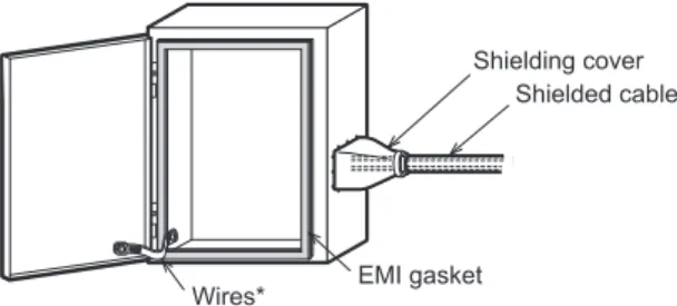
(c) To ensure that there is electrical contact between the control cabinet and its door, connect the cabinet and its doors with thick wires. (See Fig. 1.)
(d) In order to suppress the leakage of radio waves, the control cabinet must be structured with minimal openings. The gap between the control cabinet and its door must be eliminated whenever possible by attaching EMI gaskets between them. To attach an EMI gasket, remove the coating on the contact area between the control cabinet and its door and attach the EMI gasket with conductive adhesive tape. In addition, wrap the cable holes with a shielding cover or other shielding devices. (See Fig. 1.)
Mitsubishi's EMC tests were carried out on a cabinet with damping characteristics of 46.8 dB max. and 26.4 dB mean (measured by the 3-meter method from 30 MHz to 2 GHz) with an EMI gasket attached, whose damping characteristics were 69 dB mean (150 kHz to 100 MHz).
EMI gasket Wires*
Shielding cover Shielded cable
Fig. 1. Control Cabinet Example
(e) In order to avoid the effects of static electricity, make sure to eliminate static electricity when there is a possibility of touching the PLC on the control cabinet during maintenance or servicing.
(2) Cables
(a) Use shielded cables for cables that protrude out of the control cabinet.
(b) Connect the shields, such as the shielded cable and the shielding cover, to the grounded control cabinet.
* These wires are used to improve the conductivity between the door and control cabinet.
TECHNICAL BULLETIN
[ 2/4 ]
(3) Noise
fi
lter
Please attach a noise fi lter on the power line. (Refer to Fig. 4.)
Mitsubishi performed the EMC test with a common-mode noise fi lter connected in series as shown in Figs. 2 and 3.
Fig. 2. Damping characteristics of noise fi lter[1]
Fig. 3. Damping characteristics of noise fi lter[2]
Frequency (MHz)
Attenuation (dB)
100 10
1 0.1
80 60 40 20 0
Frequency (MHz)
Attenuation (dB)
(a) Separate and lay the input (power source side) and output (device side) cable away from the noise fi lter.
Do not bundle the input cable together and do not lay it close to the output cable. If input and output cables are installed together, interference may result due to noise being inducted to the input cable from the output cable.
Noise filter [1]
Noise filter [2] Noise filter
[1] Noise filter[2] Noise Noise
Bad
Good
Input cable (Power source side) Input cable
(Power source side)
Output cable (Device side) Output cable
(Device side) Induction
Installing the input and output cables together will cause noise induction.
Separate the input cable from the output cable.
Fig. 4. Precautions on noise fi lter
(b) Grounding wires of the noise fi lter should be as short as possible.
(4) Ferrite core
Always attach a ferrite core to cables that extend outside the control panel, including power cable. Mitsubishi performed the EMC test with 2 turns around NEC Tokin ESD-SR-250.
(5) Power supply
Use a DC power source other than battery to supply power to DC power type main units.
TECHNICAL BULLETIN
[ 3/4 ]
Revised History
Date Revision Description
Oct. 2014 A First Edition
Nov. 2015 B Partial design change
Oct. 2016 C Acquired certifi cation is modifi ed
The company and product names described in this technical bulletin are trademarks or registered trademarks of their respective companies.
![Fig. 2. Damping characteristics of noise fi lter[1]](https://thumb-ap.123doks.com/thumbv2/123deta/6691643.208361/3.892.182.751.313.501/fig-damping-characteristics-noise-fi-lter.webp)
