[Issue No.] GOT-A-0061-D
[Title] Precautions when Replacing GOT1000 Series with GOT2000 Series
[Date of Issue] March 2014 (Ver. D: September 2016)
[Relevant Models] GOT1000 Series (GT15 and GT16 Models)
GOT2000 Series (GT27 and
GT25 Models)
Thank you for your continued support of Mitsubishi Graphic Operation Terminal (GOT).
We released the GOT2000 series with high functions and performance as an alternative of the GOT1000 series
in September 2013. We highly recommend that you replace the GOT1000 series with the GOT2000 series for
using new sophisticated features.
Contents
1. Requests for customers ... 2
2. Replacement models ... 2
2.1 GOT ... 2
2.2 Communication unit ... 5
2.2.1 Precautions for replacement of communication units ... 6
2.3 Option unit ... 6
2.3.1 Precautions for replacement of option units ... 7
2.4 Option ... 8
2.5 Cable ... 9
2.5.1 Q bus connection cable ... 9
2.5.2 RS-232 cable ... 9
2.5.3 RS-422 cable ... 9
2.5.4 Network cable (Ethernet, MELSECNET/H, MELSECNET/10, and CC-Link)... 10
2.5.5 Other cables ... 10
2.6 Software ... 10
2.7 License ... 11
3. Comparison in specifications ... 12
3.1 Hardware specifications ... 12
3.1.1 Comparison in hardware specifications ... 12
3.1.2 Installing the GOT... 19
3.1.3 Memory card insertion direction ... 26
3.1.4 Attachment direction of the battery ... 27
3.1.5 Comparison in utility specifications... 28
3.1.6 Precautions for hardware replacement ... 32
3.1.7 Precautions for arrangement of a 2-point press switch ... 33
3.2 Function specifications ... 36
3.2.1 Comparison in functions ... 36
3.2.2 Detailed comparison in functions ... 37
3.3 Screen design software specifications ... 45
3.3.1 Preparation before converting the project data ... 45
3.3.2 Procedure for the project data conversion ... 45
3.3.3 Screen design functions that are not supported ... 47
3.3.4 Other major changes ... 47
3.4 SoftGOT specifications ... 52
3.5 Others ... 52
1. Requests for customers
We released the GOT2000 series with high functions and performance as an alternative of the GOT1000 series
in September 2013. We highly recommend that you replace the GOT1000 series with the GOT2000 series for
using new sophisticated features.
For the replacement models, refer to "Table 2-1 Recommended replacement GOT models of the GOT2000
series" in Chapter 2 below.
2. Replacement
models
"Table 2-1 Recommended replacement GOT models of the GOT2000 series" introduces recommended models
that have no or less restrictions in terms of the specifications on their replacement with the GOT2000 series.
Other models can be selected depending on the usage status in your system. Select an appropriate model after
carefully considering the range of performance in the current system.
For the precautions on the replacement, refer to each chapter and section.
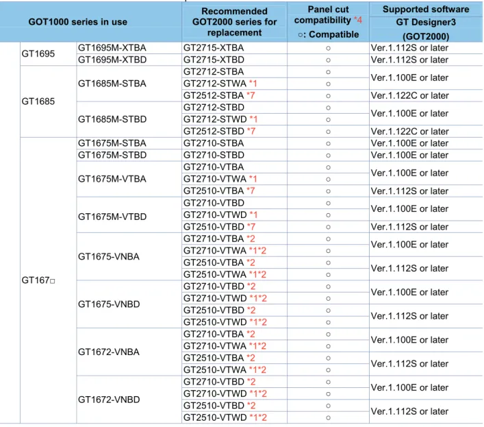
2.1 GOT
Since the panel cut dimensions for the GOT2000 series are the same as those for the GOT1000 series, the
control panel is not required to be reworked. When you use GOT2000 series shown below, the required screen
design software version differs according to the model and functions. Prepare a compatible version of the screen
design software.
Table 2-1 Recommended replacement GOT models of the GOT2000 series
GOT1000 series in use
Recommended GOT2000 series for
replacement
Panel cut compatibility *4
○: Compatible
Supported software GT Designer3
(GOT2000)
GT16
GT1695 GT1695M-XTBA GT2715-XTBA ○ Ver.1.112S or later GT1695M-XTBD GT2715-XTBD ○ Ver.1.112S or later
GT1685
GT1685M-STBA
GT2712-STBA ○
Ver.1.100E or later GT2712-STWA *1 ○
GT2512-STBA *7 ○ Ver.1.122C or later
GT1685M-STBD
GT2712-STBD ○
Ver.1.100E or later GT2712-STWD *1 ○
GT2512-STBD *7 ○ Ver.1.122C or later
GT167□
GT1675M-STBA GT2710-STBA ○ Ver.1.100E or later GT1675M-STBD GT2710-STBD ○ Ver.1.100E or later
GT1675M-VTBA
GT2710-VTBA ○
Ver.1.100E or later GT2710-VTWA *1 ○
GT2510-VTBA *7 ○ Ver.1.112S or later
GT1675M-VTBD
GT2710-VTBD ○
Ver.1.100E or later GT2710-VTWD *1 ○
GT2510-VTBD *7 ○ Ver.1.112S or later
GT1675-VNBA
GT2710-VTBA *2 ○
Ver.1.100E or later GT2710-VTWA *1*2 ○
GT2510-VTBA *2 ○
Ver.1.112S or later GT2510-VTWA *1*2 ○
GT1675-VNBD
GT2710-VTBD *2 ○
Ver.1.100E or later GT2710-VTWD *1*2 ○
GT2510-VTBD *2 ○
Ver.1.112S or later GT2510-VTWD *1*2 ○
GT1672-VNBA
GT2710-VTBA *2 ○
Ver.1.100E or later GT2710-VTWA *1*2 ○
GT2510-VTBA *2 ○
Ver.1.112S or later GT2510-VTWA *1*2 ○
GT1672-VNBD
GT2710-VTBD *2 ○
Ver.1.100E or later GT2710-VTWD *1*2 ○
GT2510-VTBD *2 ○
GOT1000 series in use
Recommended GOT2000 series for
replacement
Panel cut compatibility *4
○: Compatible
Supported software GT Designer3
(GOT2000)
GT16
GT166□
GT1665M-STBA GT2708-STBA ○ Ver.1.100E or later GT1665M-STBD GT2708-STBD ○ Ver.1.100E or later
GT1665M-VTBA GT2708-VTBA ○ Ver.1.100E or later
GT2508-VTBA *7 Ver.1.112S or later
GT1665M-VTBD GT2708-VTBD ○ Ver.1.100E or later
GT2508-VTBD *7 Ver.1.112S or later
GT1662-VNBA
GT2708-VTBA *2 ○ Ver.1.100E or later GT2508-VTBA *2 ○
Ver.1.112S or later GT2508-VTWA *1*2 ○
GT166□ GT1662-VNBD
GT2708-VTBD *2 ○ Ver.1.100E or later GT2508-VTBD *2 ○
Ver.1.112S or later GT2508-VTWD *1*2 ○
GT1655 GT1655-VTBD GT2705-VTBD ○ Ver.1.130L or later
Handy GOT GT1665HS-VTBD - *3 -
-GT15
GT1595
GT1595-XTBA
(Discontinued product) GT2715-XTBA ○ Ver.1.112S or later
GT1595-XTBD
(Discontinued product) GT2715-XTBD ○ Ver.1.112S or later
GT1585
GT1585V-STBA (Discontinued product)
GT2712-STBA *5 ○
Ver.1.100E or later GT2712-STWA *1*5 ○
GT2512-STBA *6 ○ Ver.1.122C or later
GT1585V-STBD (Discontinued product)
GT2712-STBD *5 ○
Ver.1.100E or later GT2712-STWD *1*5 ○
GT2512-STBD *6 ○ Ver.1.122C or later
GT1585-STBA (Discontinued product)
GT2712-STBA *5 ○
Ver.1.100E or later GT2712-STWA *1*5 ○
GT2512-STBA *6 ○ Ver.1.122C or later
GT1585-STBD (Discontinued product)
GT2712-STBD *5 ○
Ver.1.100E or later GT2712-STWD *1*5 ○
GT2512-STBD *6 ○ Ver.1.122C or later
GT157□
GT1575V-STBA
(Discontinued product) GT2710-STBA *5 ○
Ver.1.100E or later GT1575V-STBD
(Discontinued product) GT2710-STBD *5 ○
GT1575-STBA
(Discontinued product) GT2710-STBA *5 ○
GT1575-STBD
(Discontinued product) GT2710-STBD *5 ○
GT1575-VTBA (Discontinued product)
GT2710-VTBA *5 ○
Ver.1.100E or later GT2710-VTWA *1*5 ○
GT2510-VTBA *6 ○
Ver.1.112S or later GT2510-VTWA *1*6 ○
GT1575-VTBD (Discontinued product)
GT2710-VTBD *5 ○
Ver.1.100E or later GT2710-VTWD *1*5 ○
GT2510-VTBD *6 ○
Ver.1.112S or later GT2510-VTWD *1*6 ○
GT1575-VNBA (Discontinued product)
GT2710-VTBA *2*5 ○
Ver.1.100E or later GT2710-VTWA *1*2*5 ○
GT2510-VTBA *2*6 ○
Ver.1.112S or later GT2510-VTWA *1*2*6 ○
GT1575-VNBD (Discontinued product)
GT2710-VTBD *2*5 ○
Ver.1.100E or later GT2710-VTWD *1*2*5 ○
GT2510-VTBD *2*6 ○
GOT1000 series in use
Recommended GOT2000 series for
replacement
Panel cut compatibility *4
○: Compatible
Supported software GT Designer3
(GOT2000)
GT15
GT157□
GT1572-VNBA (Discontinued product)
GT2710-VTBA *2*5 ○
Ver.1.100E or later GT2710-VTWA *1*2*5 ○
GT2510-VTBA *2*6 ○
Ver.1.112S or later GT2510-VTWA *1*2*6 ○
GT1572-VNBD (Discontinued product)
GT2710-VTBD *2*5 ○
Ver.1.100E or later GT2710-VTWD *1*2*5 ○
GT2510-VTBD *2*6 ○
Ver.1.112S or later GT2510-VTWD *1*2*6 ○
GT156□
GT1565-VTBA (Discontinued product)
GT2708-VTBA *5 ○ Ver.1.100E or later GT2508-VTBA *6 ○
Ver.1.112S or later GT2508-VTWA *1*6 ○
GT1565-VTBD (Discontinued product)
GT2708-VTBD *5 ○ Ver.1.100E or later GT2508-VTBD *6 ○
Ver.1.112S or later GT2508-VTWD *1*6 ○
GT156□
GT1562-VNBA (Discontinued product)
GT2708-VTBA *2*5 ○ Ver.1.100E or later GT2508-VTBA *2*6 ○
Ver.1.112S or later GT2508-VTWA *1*2*6 ○
GT1562-VNBD (Discontinued product)
GT2708-VTBD *2*5 ○ Ver.1.100E or later GT2508-VTBD *2*6 ○
Ver.1.112S or later GT2508-VTWD *1*2*6 ○
GT155□
GT1555-VTBD GT2705-VTBD *5 ○ Ver.1.130L or later
GT1555-QTBD - *3 -
-GT1555-QSBD - *3 -
-GT1550-QLBD - *3 -
-*1 This model has a white front panel. For the difference in the specifications between the white-panel model and standard model (black panel), refer to Section 3.1.1.
*2 The display color is changed to 65536 colors since the GOT2000 series does not support 4096, 256, and 16 colors. Note that the price range differs. For the details, refer to the GOT2000 series catalog (L(NA)08274ENG).
*3 No models for replacement are prepared.
*4 The panel cutting dimensions are compatible; however, the external dimensions are longer upward and downward by 2 mm. *5 Although the display type is changed from the matrix resistive film type to the analog resistive film type, 2-point press is
available.
However, note that there are precautions on the arrangement of 2-point press switches. For the details, refer to Section 3.1.7. *6 The display section is changed from a matrix-resistive touch panel type to an analog-resistive touch panel type.
The 2-point press is unavailable.
2.2 Communication
unit
Most of the communication units of the GOT1000 series can be used together with the GOT2000 series as-is.
Check the availability of use in the following table.
Table 2-2 List of replacement models for communication units
◎: Available as-is ᇞ: Replaceable Communication format GOT1000 model Availability
of use Remarks
Q bus connection
GT15-QBUS ◎ -
GT15-75QBUSL ◎
To use the units for the external I/O function, sound output function, printer function, video/RGB input or output function, and other functions in combination, use the following unit.
GT15-QBUS (Q bus connection, 1 channel)
GT15-QBUS2 ◎
To use a GT15-QBUS2 unit removed from a GOT (GOT1000 series), remove the extension interface relay board from the unit, and then mount only the unit on a GOT (GOT2000 series).
GT15-75QBUS2L ◎
To use the units for the external I/O function, sound output function, printer function, video/RGB input or output function, and other functions in combination, use the following unit.
GT15-QBUS2 (Q bus connection, 2 channels)
RS-232 connection GT15-RS2-9P ◎ -
RS-422 connection
GT15-RS4-9S ◎ -
GT15-RS4-TE ◎ -
GT15-RS2T4-9P ᇞ
Use the built-in RS-422/485 interface or RS-422/485 serial communication unit (GT15-RS4-9S) sold separately.
MELSECNET/10 connection *1
GT15-J71LP23-25 ◎
To use a GT15-J71LP23-25 unit removed from a GOT (GOT1000 series), remove the extension interface relay board from the unit, and then mount only the unit on a GOT (GOT2000 series).
GT15-75J71LP23-Z ᇞ
Not available.
Replace with the MELSECNET/H communication unit (GT15-J71LP23-25).
GT15-J71BR13 ◎
To use a GT15-J71BR13 unit removed from a GOT (GOT1000 series), remove the extension interface relay board from the unit, and then mount only the unit on a GOT (GOT2000 series).
GT15-75J71BR13-Z ᇞ
Not available.
Replace with the MELSECNET/H communication unit (GT15-J71BR13).
MELSECNET/H connection
GT15-J71LP23-25 ◎
To use a GT15-J71LP23-25 unit removed from a GOT (GOT1000 series), remove the extension interface relay board from the unit, and then mount only the unit on a GOT (GOT2000 series).
GT15-J71BR13 ◎
To use a GT15-J71BR13 unit removed from a GOT (GOT1000 series), remove the extension interface relay board from the unit, and then mount only the unit on a GOT (GOT2000 series). CC-Link IE Controller
Network communication unit
GT15-J71GP23-SX ◎
To use a GT15-J71GP23-SX unit removed from a GOT (GOT1000 series), remove the extension interface relay board from the unit, and then mount only the unit on a GOT (GOT2000 series).
CC-Link IE Field Network
communication unit GT15-J71GF13-T2 ◎
To use a GT15-J71GF13-T2 unit removed from a GOT (GOT1000 series), remove the extension interface relay board from the unit, and then mount only the unit on a GOT (GOT2000 series). CC-Link(ID) connection
Ver.1 GT15-75J61BT13-Z ᇞ
Not available.
Replace with GT15-J61BT13.
CC-Link(ID) connection
Ver.2 GT15-J61BT13 ◎
To use a GT15-J61BT13 unit removed from a GOT (GOT1000 series), remove the extension interface relay board from the unit, and then mount only the unit on a GOT (GOT2000 series). Ethernet connection GT15-J71E71-100 ᇞ Use the built-in interface (Ethernet).
Serial multi-drop
connection unit GT01-RS4-M ◎ -
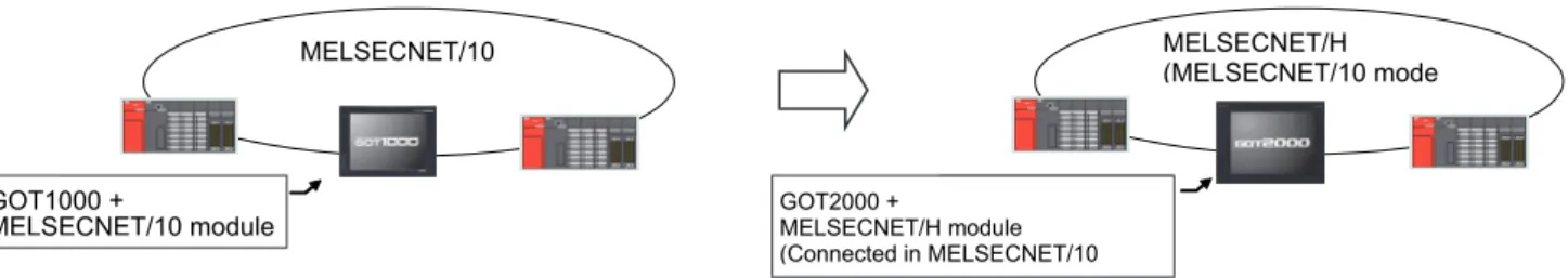
2.2.1
Precautions for replacement of communication units
(1) Replacing the GOT1000 series connected to the MELSECNET/10 (programmable controller to programmable
controller optical loop/coaxial bus)) network system with the GOT2000 series
Use the MELSECNET/H communication unit listed in Section 2.2, set the MELSECNET/H communication unit to
the MELSECNET/10 mode, and connect the GOT to the MELSECNET/10 network system.
* For the details, refer to "GOT2000 Series Connection Manual (Mitsubishi Product) For GT Works3 Version1
(SH-081197ENG)".
Figure 2-1 Replacement example that requires a change in the network system configuration
2.3 Option
unit
Most of the option units of the GOT1000 series can be used together with the GOT2000 series as-is. Check the
availability of use in the following table.
Table 2-3 List of replacement models for option units
◎: Available as-is ᇞ: Replaceable ×: Not available
Option unit GOT1000 model Availability of use Remarks
Printer unit GT15-PRN ◎
Supported by GT Designer3 (GOT2000) Ver.1.105K or later.
Multimedia unit GT16M-MMR ᇞ Use a unit for the GOT2000 series (GT27-MMR-Z).* The applicable memory card is CF cards.
Video input unit
GT16M-V4
ᇞ
Use a unit for the GOT2000 series (GT27-V4-Z). To use the unit on GT2715 and to comply with the EMC Directive, use the unit with whose hardware version is B or later. *1
GT15V-75V4
(Discontinued product)
RGB input unit
GT16M-R2
ᇞ
Use a unit for the GOT2000 series (GT27-R2 or GT27-R2-Z).
To use GT27-R2-Z on GT2715 in compliance with the EMC Directive, the GT27-R2-Z must have hardware version B or later.*1
GT15V-75R1 (Discontinued product)
Video/RGB input unit
GT16M-V4R1
ᇞ
Use a unit for the GOT2000 series (GT27-V4R1-Z). To use the unit on GT2715 and to comply with the EMC Directive, use the unit with whose hardware version is B or later.*1
GT15V-75V4R1 (Discontinued product)
RGB output unit
GT16M-ROUT
ᇞ Use a unit for the GOT2000 series (GT27-ROUT or GT27-ROUT-Z). GT15V-75ROUT
(Discontinued product)
Sound output unit GT15-SOUT ◎ -
CF card unit GT15-CFCD × CF cards are unavailable to the GOT2000 series. Use SD cards or USB memory devices.
CF card extension unit GT15-CFEX-C08SET × CF cards are unavailable to the GOT2000 series. Use SD cards or USB memory devices.
External I/O unit GT15-DIOR
◎ -
GT15-DIO ◎ -
*1 To use the unit on GT2715, the hardware version of the supplied GT16M-V4R1-Z/GT16M-V4-Z/GT16M-R2-Z and GT27-IF1000 must also be B or later.
MELSECNET/10
GOT1000 + MELSECNET/10 ユニット
MELSECNET/10
GOT1000 +
MELSECNET/10 module
MELSECNET/H
(MELSECNET/10 モード)
GOT2000 + MELSECNET/H ユニット
(MELSECNET/10 モードで接続)
MELSECNET/H (MELSECNET/10 mode
GOT2000 +
2.3.1
Precautions for replacement of option units
When an option unit for the GOT1000 series is replaced with that for the GOT2000 series, the height of the
replacement unit may differ. Check the height in the following table.
Table 2-4 List of the height of option units
Unit (mm)
Option unit GT27□□ GT1695 GT1685 GT1675 GT1665
Multimedia unit (GT27-MMR-Z) 58.0 - - - -
Multimedia unit (GT16M-MMR) - 33.5 32.0 35.0 37.0
Video input unit (GT27-V4-Z) 44.5 - - - -
Video input unit (GT16M-V4) - 19.5 18.0 21.0 23.0
RGB input unit (GT27-R2) 20.0 - - - -
RGB input unit (GT27-R2-Z) 44.5 - - - -
RGB input unit (GT16M-R2) - 19.5 18.0 21.0 23.0 Video/RGB input unit (GT27-V4R1-Z) 44.5 - - - - Video/RGB input unit (GT16M-V4R1) - 19.5 18.0 21.0 23.0
RGB output unit (GT27-ROUT) 20.0 - - - -
RGB output unit (GT27-ROUT-Z) 44.5 - - - -
RGB output unit (GT16-ROUT) - 19.5 18.0 21.0 23.0 Option unit
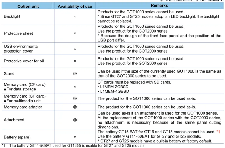
2.4 Option
For options, use the products for the GOT2000 series. Some options can be used as is.
Check the availability of use in the following table.
Table 2-5 List for option replacement
◎: Available as-is ×: Not available
Option unit Availability of use Remarks
Backlight ×
Products for the GOT1000 series cannot be used.
* Since GT27 and GT25 models adopt an LED backlight, the backlight cannot be replaced.
Protective sheet ×
Products for the GOT1000 series cannot be used. Use the product for the GOT2000 series.
* Because the design of the front face panel and the position of the USB port differ.
USB environmental
protection cover ×
Products for the GOT1000 series cannot be used. Use the product for the GOT2000 series.
Protective cover for oil × Products for the GOT1000 series cannot be used. Use the product for the GOT2000 series.
Stand ◎
Can be used if the size of the currently used GOT1000 is the same as that of the GOT2000 series to be used.
Memory card (CF card)
■For data storage ×
CF cards must be replaced with SD cards. • L1MEM-2GBSD
• L1MEM-4GBSD Memory card (CF card)
■For multimedia unit ◎ The product for the GOT1000 series can be used as-is.
Memory card adapter ◎ The product for the GOT1000 series can be used as-is.
Attachment ◎
Can be used as-is if an attachment is used for the GOT1000 series. At the replacement of the GOT1000 series with the GOT2000 series, no attachment is necessary because of the same panel cutting dimensions.
Battery (spare) ×
The battery GT15-BAT for GT16 and GT15 models cannot be used. *1 Use the battery GT11-50BAT for GT27 and GT25 models.
* GT27 and GT25 models have a built-in battery at factory default. *1 The battery GT11-50BAT used for GT1655 is usable for GT27 and GT25 models.
2.5 Cable
2.5.1
Q bus connection cable
(1) Utilization of cables in present use
The currently used Q bus connection cable for the GOT1000 series can be used as-is for the GOT2000 series.
(2) Replacing GOT when using multiple units of bus connection
When multiple GOT1000-series GOTs are connected by the Q bus connection, one or more of the units can be
replaced with the GOT2000 series. In this case, the GOT1000 series and GOT2000 series can coexist in the
same system.
■
Configuration with GOT1000 only
The GOT1000 series and GOT2000 series can coexist.
2.5.2 RS-232
cable
The currently used cable for the GOT1000 series can be used as-is for the GOT2000 series.
2.5.3 RS-422
cable
(1) Cable for GT15 models
The existing GOT1000 cables used for GT15 models are usable for the GOT2000 series.
(2) Cable for GT16 models
Whether the cables for GT16 models can be used depends on the communication interface or the
communication unit routed. Check the availability of use in the following table. The cables used for the serial
communication unit (GT15-RS4-9S or GT15-RS4-TE) can be used as-is. The cables used for the RS-422/RS485
interfaces built into GT16 can be used after GT16-C02R4-9S is removed. (GT16-C02R4-9S is no longer
needed.)
Table 2-6 Replacement of RS-422 cable for GT16 models
System configuration of GOT1000 System configuration of GOT2000
Communication port (built-in GOT)
Communication
unit/conversion cable Cable Cable model
RS-422/485 port built in GT16
GT16-C02R4-9S GT01-C□□R4-25P (or equivalent)
The currently used RS-422 conversion cable (GT16-C02R4-9S) is no longer needed. The cable (GT01-C□□R4-25P) can be used as-is.
* The RS-422/485 port built in GT27 and GT25 is used for the communication port.
Extension interface of GT16
GT15-RS4-9S GT01-C□□R4-25P (or equivalent)
The currently used communication unit and cables can be used as-is.
RS-232 port built in GT16
GT15-RS2T4-9P GT01-C□□R4-25P (or equivalent)
The currently used communication unit
(GT15-RS2T4-9P) is no longer needed. The cable (GT01-C□□R4-25P) can be used as-is.
* The RS-422/485 port built in GT27 and GT25 is used for the communication port.
* □ in the table indicates a number representing the length.
GOT1000 用 Q バ ケーブ
GOT1000 シ ー
GOT1000 用 Q バ ケーブ
GOT1000 シ ー
GOT1000 series GOT1000 series
GOT1000 Q bus connection cable
GOT1000 Q bus
connection cable GOT1000 用 Q バ ケーブ
GOT1000 シ ー
GOT1000 用 Q バ ケーブ
GOT2000 シ ー
GOT1000 series GOT2000 series
GOT1000 Q bus connection cable
2.5.4
Network cable (Ethernet, MELSECNET/10, and CC-Link)
The GOT1000 series network cables are applicable to the GOT2000 series.
2.5.5 Other
cables
The following the GOT1000 series cables are applicable to the GOT2000 series.
Table 2-7 Availability of other currently used cables
◎: Available as-is ×: Not available
Cable of GOT1000 Cable of GOT2000
Cable name Cable model Availability of use Remarks
Printer cable GT09-C30USB-5P when a printer
unit (GT15-PRN) is used ◎
-User-fabricated cable when a serial
printer is used ◎
-Analog RGB cable GT15-C50VG or user-fabricated cable
◎
For connection with a device that can output images by RGB, such as video cameras, vision sensors, and personal computers, and with an external monitor
Coaxial cable for video display
User-fabricated cable
◎
For connection with a device that can output images by NTSC/PAL, such as video cameras and vision sensors
2.6 Software
To create project data for the GOT2000 series, MELSOFT GT Designer3 (GOT2000), which is included with the
screen design software MELSOFT GT Works3 (Version 1.100E or later), is needed.
For how to obtain the software in a specific version, refer to the following table.
Table 2-8 Supported software version and how to obtain the software
Software Supported version How to obtain the software
Screen design software MELSOFT GT Works3
■Japanese/English/Chinese version MELSOFT GT Designer3 (GOT2000), which is enclosed with MELSOFT GT Works3 Version 1.100E or later
The version shown on the left is supported. If your version is old, update the software to the latest version, 1.100E or later. For how to obtain the software, contact your local sales office.
Screen design software MELSOFT GT Works2 MELSOFT GT Designer2
Not supported
To create project data for the GOT2000 series, purchase MELSOFT GT Works3 Version 1.100E or later.
FA integrated engineering software
MELSOFT iQ Works
■Japanese version
Ver.1.71Z or later is supported.
■English version
Ver.1.77F or later is supported.
2.7 License
The GOT1000 series licenses below cannot be used for the GOT2000 series. Please purchase the GOT2000
series licenses.
Table 2-9 List of replacement models for option units
×: Model change required License name
(license key for GOT1000)
Availability of use
(license key for GOT2000) Remarks
License key for GT SoftGOT (GT15-SGTKEY-U)
×
(GT27-SGTKEY-U) Use the license for GT SoftGOT2000. License of the remote personal
computer operation (Ethernet) (GT16-PCRAKEY)
×
(GT25-PCRAKEY) Use the license for GOT2000.
License of the VNC server function (GT16-VNCSKEY)
×
(GT25-VNCSKEY) Use the license for GOT2000. License of MES interface function
(GT16-MESB,GT15-MESB48M) *1
×
(GT25-MESIFKEY) Use the license for GOT2000.
*1 The MES interface function of the GOT1000 series requires the product activation by the option function board, but the MES interface function of the GOT2000 series can be activated with a license number.
3. Comparison in specifications
The following describes the differences in the specifications between the GOT1000 series and GOT2000 series.
When considering a replacement of the GOT1000 series with the GOT2000 series, check the specifications of
your current model and target model.
3.1 Hardware
specifications
3.1.1
Comparison in hardware specifications
The following describes the comparison in the hardware specifications between the GOT1000 series and
GOT2000 series.
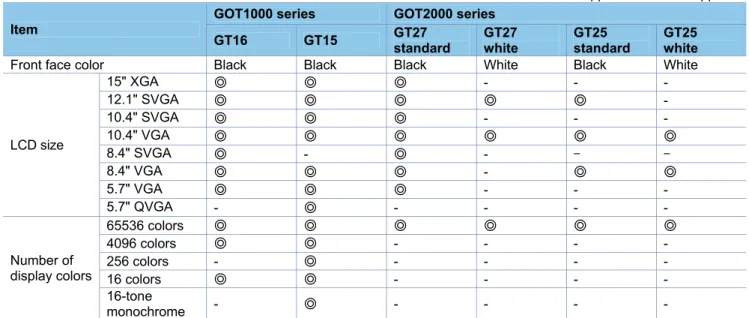
(1) Lineup
Table 3-1 Lineup comparison
◎: Supported -: Not supported
Item
GOT1000 series GOT2000 series
GT16 GT15 GT27
standard
GT27 white
GT25 standard
GT25 white Front face color Black Black Black White Black White
LCD size
15" XGA ◎ ◎ ◎ - -
-12.1" SVGA ◎ ◎ ◎ ◎ ◎
-10.4" SVGA ◎ ◎ ◎ - -
-10.4" VGA ◎ ◎ ◎ ◎ ◎ ◎
8.4" SVGA ◎ - ◎ - -
-8.4" VGA ◎ ◎ ◎ - ◎ ◎
5.7" VGA ◎ ◎ ◎ - -
-5.7" QVGA - ◎ - - -
-Number of display colors
65536 colors ◎ ◎ ◎ ◎ ◎ ◎
4096 colors ◎ ◎ - - -
-256 colors - ◎ - - -
-16 colors ◎ ◎ - - -
-16-tone
-(2) External dimensions
The external dimensions of the GOT2000 series are larger than those of the GOT1000 series upward and
downward by 2 mm. However, the panel cutting dimensions and mounting intervals are the same.
For the panel cutting dimensions and mounting intervals, refer to Section 3.1.2.
■
15” (GOT1000 series)
■
15” (GOT2000 series)
GT1695
29
6
320
61
6
382
10 10
10
28
1
10
397
320 GT1595
10
28
1
10
397 320
29
6
320
61 65
382
10 10
GT2715
397
322
300
20
322
10
281
10 6
60 46
■
12.1” (GOT1000 series)
■
12.1” (GOT2000 series)
GT1685
316 240
24
2
10
10
22
7
301
56 52
6
240
301 250 316 263
10
10
56 6 52
5
227 242
GT1585
GT2712
GT2512
316246
227
10
10
52
6
241
241
■
10.4” (GOT1000 series)
■
10.4” (GOT2000 series)
49
288
6
56
222
21
4
10
19
9
10
GT167□
303 252
GT157□
303 252
222
288
10
10
49
56
5
6
19
9
21
4
GT2710 GT2510
303 208
228
288
218
19
9
10
10
52
■
8.4” (GOT1000 series)
■
8.4” (GOT2000 series)
GT166□
10
10
1
75
175.5 24 1
19
0
175.5
6
56
22 6
52
GT156□
226 175.5 175.5 241
56
19
0
17
5
10
10
52
65
GT2708 GT2508
241
166 37.5
37.5
226 171.6
175 19
4
10
10
52
■
5.7” (GOT1000 series)
■
5.7” (GOT2000 series)
GT1655
120
10
10
116
116
152 167
135
60
6
GT155□
60 65
12
0
10
10
152
135
167 110
110
152 167 117
89
13
9
12
0
10
10
60
6
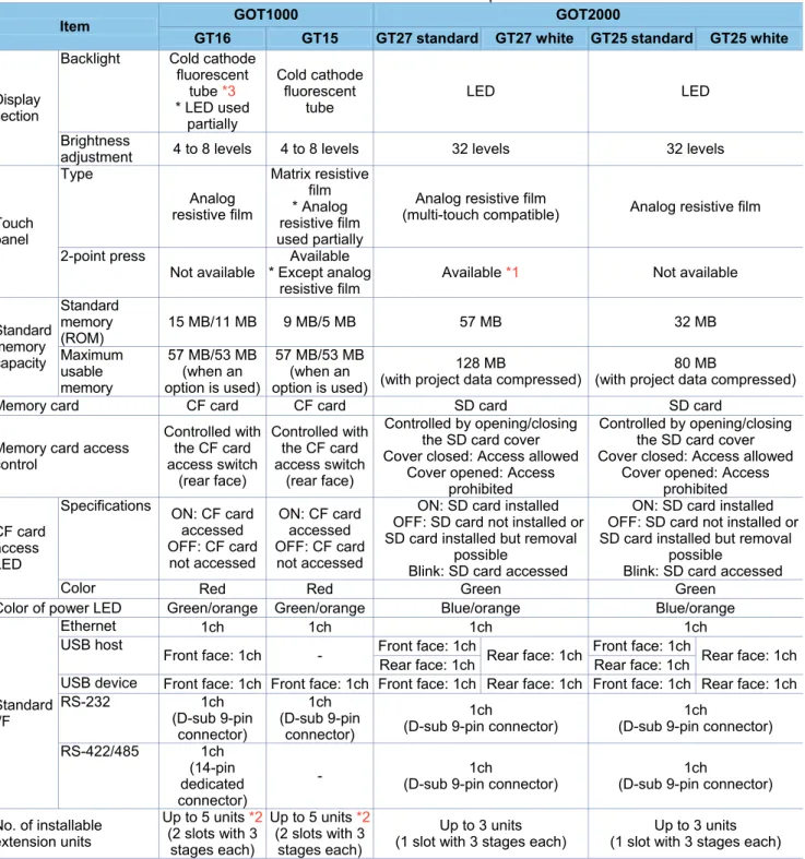
(3) Performance specifications
The following describes the comparison in the performance specifications between the GOT1000 series and
GOT2000 series.
Table 3-2 Performance comparison
Item GOT1000 GOT2000
GT16 GT15 GT27 standard GT27 white GT25 standard GT25 white
Display section
Backlight Cold cathode fluorescent
tube *3 * LED used
partially Cold cathode fluorescent tube LED LED Brightness
adjustment 4 to 8 levels 4 to 8 levels 32 levels 32 levels
Touch panel Type Analog resistive film Matrix resistive film * Analog resistive film used partially
Analog resistive film
(multi-touch compatible) Analog resistive film
2-point press
Not available
Available * Except analog
resistive film
Available *1 Not available
Standard memory capacity Standard memory (ROM)
15 MB/11 MB 9 MB/5 MB 57 MB 32 MB
Maximum usable memory
57 MB/53 MB (when an option is used)
57 MB/53 MB (when an option is used)
128 MB
(with project data compressed)
80 MB
(with project data compressed)
Memory card CF card CF card SD card SD card
Memory card access control
Controlled with the CF card access switch
(rear face)
Controlled with the CF card access switch
(rear face)
Controlled by opening/closing the SD card cover Cover closed: Access allowed
Cover opened: Access prohibited
Controlled by opening/closing the SD card cover Cover closed: Access allowed
Cover opened: Access prohibited
CF card access LED
Specifications
ON: CF card accessed OFF: CF card
not accessed
ON: CF card accessed OFF: CF card not accessed
ON: SD card installed OFF: SD card not installed or SD card installed but removal
possible
Blink: SD card accessed
ON: SD card installed OFF: SD card not installed or SD card installed but removal
possible
Blink: SD card accessed
Color Red Red Green Green
Color of power LED Green/orange Green/orange Blue/orange Blue/orange
Standard I/F
Ethernet 1ch 1ch 1ch 1ch
USB host
Front face: 1ch - Front face: 1ch Rear face: 1ch Front face: 1ch Rear face: 1ch Rear face: 1ch Rear face: 1ch
USB device Front face: 1ch Front face: 1ch Front face: 1ch Rear face: 1ch Front face: 1ch Rear face: 1ch RS-232 1ch (D-sub 9-pin connector) 1ch (D-sub 9-pin connector) 1ch
(D-sub 9-pin connector)
1ch
(D-sub 9-pin connector)
RS-422/485 1ch (14-pin dedicated connector)
- (D-sub 9-pin connector)1ch (D-sub 9-pin connector)1ch
No. of installable extension units
Up to 5 units *2 (2 slots with 3 stages each)
Up to 5 units*2 (2 slots with 3 stages each)
Up to 3 units (1 slot with 3 stages each)
Up to 3 units (1 slot with 3 stages each)
*1 Note the there are precautions on the arrangement of 2-point press switches. For the details, refer to Section 3.1.7.
*2 Up to three units can be mounted on GT1655 or GT155□.
3.1.2
Installing the GOT
(1) Panel cutting dimensions
The panel cutting dimensions for GOT installation are as follows. Cut an attachment hole on the panel in the
following dimensions.
As the extra spaces, GT2715 requires 10 mm all around the installation fitting, and other models require 10 mm
on the top and the bottom of the installation fitting respectively.
Table 3-3 Panel cutting dimension comparison
Unit (mm)
Screen size
Type
Panel cutting dimensions
GOT1000
GOT2000
A
B
GT16
GT15
GT27
GT25
15"
GT1695
GT1595
GT2715
-
383.5
282.5
12.1"
GT1685
GT1585
GT2712
GT2512
302
228
10.4"
GT167
□
GT157
□
GT2710
GT2510
289
200
8.4"
GT166
□
GT156
□
GT2708
GT2508
227
176
5.7"
GT1655
GT155
□
GT2705
-
153
121
* The panel cutting dimensions are the same when a GOT is replaced with a model having the same screen size. When replacing a GOT with a model having a different screen size, change the panel cutting dimensions according to the table above.
(2) Panel thickness
The thickness of the panel to which a GOT can be mounted is as follows.
Table 3-4 Panel thickness
Unit (mm)
Item
Type
GOT1000
GOT2000
GT16
GT15
GT27
GT25
Panel thickness to
which a GOT can
be mounted
2 to 4
2 to 4
1.6 to 4
1.6 to 4
Panel opening
(3) Mounting intervals
When installing a GOT, intervals are required from other devices, as shown below.
When replacing the GOT1000 series with the GOT2000 series, mounting intervals may differ. Check the intervals
thoroughly when mounting the GOT.
When installing a communication unit or option unit on the GOT after replacement of the GOT1000 series to use
the multi-channel function, refer to user's manual of each communication unit and/or option for the dimension E.
Depending on the units or cables used for the GOT, extra intervals larger than the described dimensions may be
required. Mount the GOT with careful consideration on the connector dimensions and cable bending radius.
The following describes the difference in mounting intervals between the GOT1000 series and GOT2000 series.
When mounting the GOT, follow the dimensions on the table and keep it properly away from other devices.
The values enclosed in brackets apply when no other devices generating radiated noise, such as a contactor, or
heat is installed near the GOT. Even in that case, however, keep the ambient temperature of the GOT to 55°C or
lower.
Besides, mounting intervals A and B differ by 2 mm between the GOT1000 series and GOT2000 series. This is
because the external dimensions for GT27 and GT25 models are larger by 2 mm in the vertical (A
and B)
direction. However, the mounting intervals between mounted GOTs and other devices are the same.
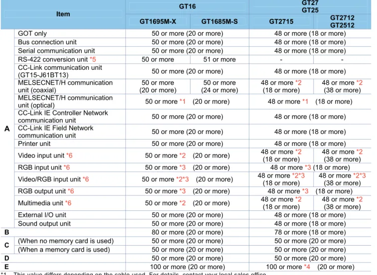
1) Comparison in mounting dimensions between GT16 and GT27/GT25 models (15" and 12.1")
Table 3-5 Comparison of mounting dimensions between GT16 and GT27/GT25 models (15" and 12.1")
Unit (mm)
Item
GT16 GT27
GT25
GT1695M-X GT1685M-S GT2715 GT2712GT2512
A
GOT only 50 or more (20 or more) 48 or more (18 or more) Bus connection unit 50 or more (20 or more) 48 or more (18 or more) Serial communication unit 50 or more (20 or more) 48 or more (18 or more) RS-422 conversion unit *5 50 or more 51 or more - -CC-Link communication unit
(GT15-J61BT13) 50 or more (20 or more) 48 or more (18 or more) MELSECNET/H communication
unit (coaxial)
50 or more (20 or more)
50 or more (24 or more)
48 or more *2 (18 or more)
48 or more *2 (38 or more) MELSECNET/H communication
unit (optical) 50 or more *1 (20 or more) 48 or more *1 (18 or more) CC-Link IE Controller Network
communication unit 50 or more (20 or more) 48 or more (18 or more) CC-Link IE Field Network
communication unit 50 or more (20 or more) 48 or more (18 or more) Printer unit 50 or more (20 or more) 48 or more (18 or more)
Video input unit *6 50 or more *2 (20 or more) 48 or more *2(18 or more) 48 or more *2(38 or more)
RGB input unit *6 50 or more *3 (20 or more) 48 or more *3 (18 or more)
Video/RGB input unit *6 50 or more *2*3 (20 or more) 48 or more *2*3(18 or more) 48 or more *2*3(38 or more)
RGB output unit *6 50 or more *3 (20 or more) 48 or more *3 (18 or more)
Multimedia unit *6 50 or more *2 (20 or more) 48 or more *2(18 or more) 48 or more *2(38 or more)
External I/O unit 50 or more (20 or more) 48 or more (18 or more) Sound output unit 50 or more (20 or more) 48 or more (18 or more) B 80 or more (20 or more) 78 or more (18 or more)
C (When no memory card is used) 50 or more (20 or more) 50 or more (20 or more) (When a memory card is used) 50 or more (20 or more) 50 or more (20 or more) D 50 or more (20 or more) 50 or more (20 or more) E 100 or more (20 or more) 100 or more *4 (20 or more) *1 This value differs depending on the cable used. For details, contact your local sales office.
The value indicated in the table is a reference value.
*2 This value is for when a coaxial cable 3C-2V (JIS C 3501) is used. Refer to the GOT2000 series connection manual for the device to be connected.
*3 This value differs depending on the cable used. If the bending radius of the cable used is greater than the value specified above, the dimension must follow the radius.
*4 When opening or closing the battery cover: 72 or more *5 Cannot be used with the GOT2000 series.
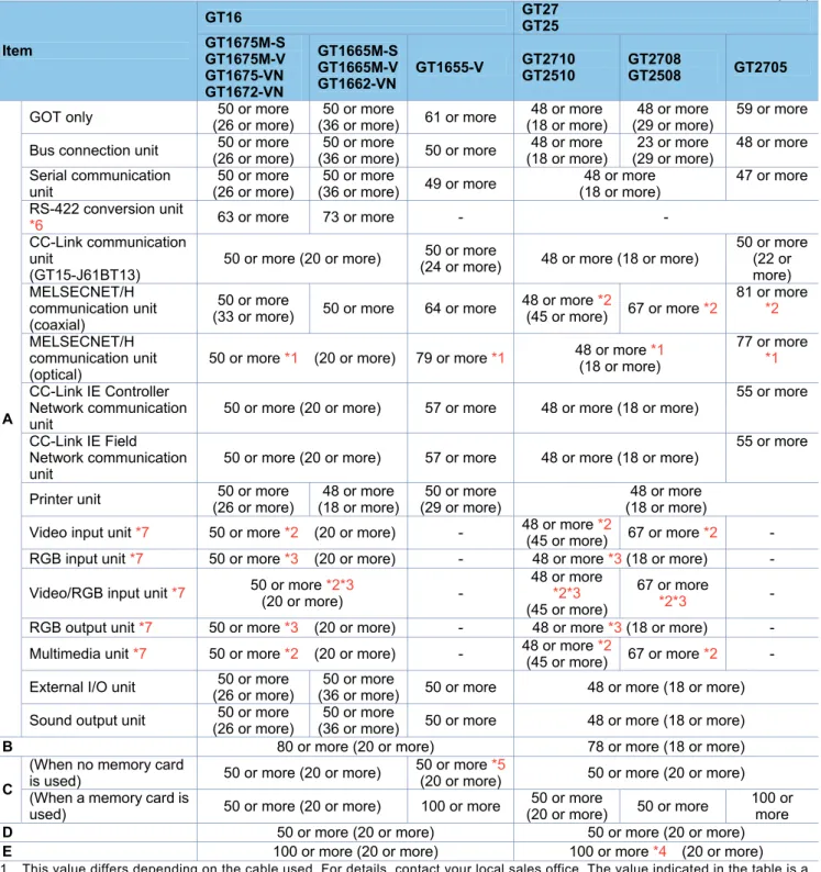
2) Comparison in mounting dimensions between GT16 and GT27/GT25 models (10.4", 8.4", and 5.7")
Table 3-6 Comparison of mounting dimensions between GT16 and GT27/GT25 models (10.4", 8.4", and 5.7")
Unit (mm) Item GT16 GT27 GT25 GT1675M-S GT1675M-V GT1675-VN GT1672-VN GT1665M-S GT1665M-V GT1662-VN
GT1655-V GT2710 GT2510 GT2708 GT2508 GT2705
A
GOT only (26 or more)50 or more (36 or more)50 or more 61 or more (18 or more)48 or more (29 or more)48 or more 59 or more
Bus connection unit 50 or more (26 or more)
50 or more
(36 or more) 50 or more
48 or more (18 or more)
23 or more (29 or more)
48 or more
Serial communication unit
50 or more (26 or more)
50 or more
(36 or more) 49 or more
48 or more (18 or more)
47 or more
RS-422 conversion unit
*6 63 or more 73 or more - -
CC-Link communication unit
(GT15-J61BT13)
50 or more (20 or more) (24 or more)50 or more 48 or more (18 or more)
50 or more (22 or more) MELSECNET/H
communication unit (coaxial)
50 or more
(33 or more) 50 or more 64 or more
48 or more *2
(45 or more) 67 or more *2
81 or more *2
MELSECNET/H communication unit (optical)
50 or more *1 (20 or more) 79 or more *1 48 or more *1 (18 or more)
77 or more *1
CC-Link IE Controller Network communication unit
50 or more (20 or more) 57 or more 48 or more (18 or more)
55 or more
CC-Link IE Field Network communication unit
50 or more (20 or more) 57 or more 48 or more (18 or more)
55 or more
Printer unit 50 or more (26 or more)
48 or more (18 or more)
50 or more (29 or more)
48 or more (18 or more)
Video input unit *7 50 or more *2 (20 or more) - 48 or more *2(45 or more) 67 or more *2 -
RGB input unit *7 50 or more *3 (20 or more) - 48 or more *3 (18 or more) -
Video/RGB input unit *7 50 or more *2*3 (20 or more)
-48 or more *2*3 (45 or more)
67 or more
*2*3 -
RGB output unit *7 50 or more *3 (20 or more) - 48 or more *3 (18 or more) -
Multimedia unit *7 50 or more *2 (20 or more) - 48 or more *2
(45 or more) 67 or more *2 -
External I/O unit (26 or more)50 or more (36 or more)50 or more 50 or more 48 or more (18 or more)
Sound output unit (26 or more)50 or more (36 or more)50 or more 50 or more 48 or more (18 or more)
B 80 or more (20 or more) 78 or more (18 or more)
C
(When no memory card
is used) 50 or more (20 or more)
50 or more *5
(20 or more) 50 or more (20 or more) (When a memory card is
used) 50 or more (20 or more) 100 or more
50 or more
(20 or more) 50 or more
100 or more D 50 or more (20 or more) 50 or more (20 or more) E 100 or more (20 or more) 100 or more *4 (20 or more) *1 This value differs depending on the cable used. For details, contact your local sales office. The value indicated in the table is a
reference value.
*2 This value is for when a coaxial cable 3C-2V (JIS C 3501) is used. Refer to the GOT2000 series connection manual for the device to be connected.
*3 This value differs depending on the cable used. If the bending radius of the cable used is greater than the value specified above, the dimension must follow the radius.
*4 When opening or closing the battery cover: 72 or more
*5 This value is for when no battery is used. If a battery is used, the dimension when a CF card is used is required. *6 Cannot be used with the GOT2000 series.
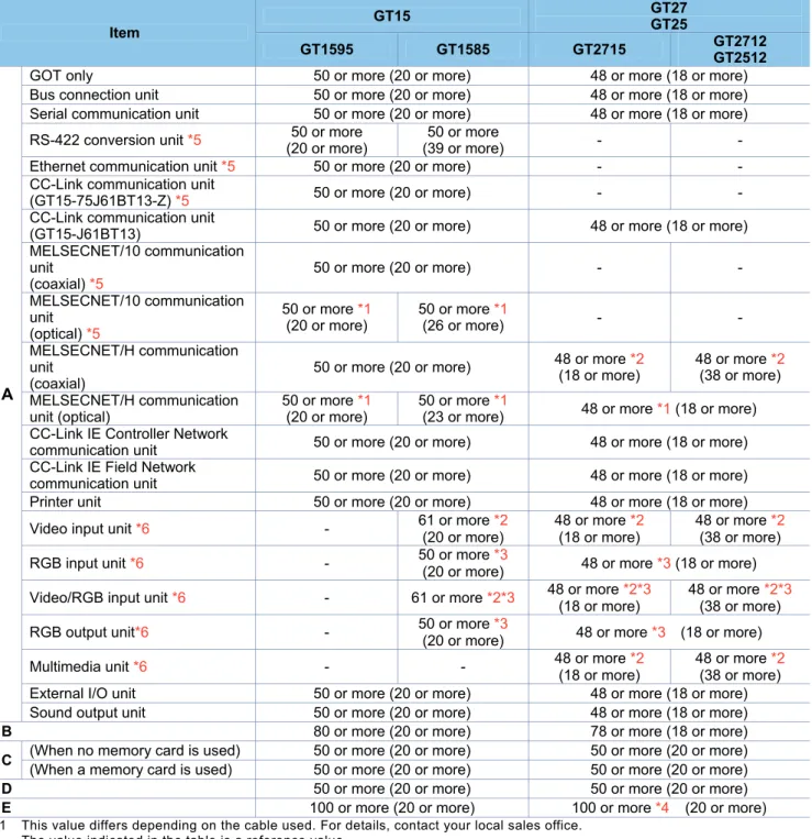
3) Comparison in mounting dimensions between GT15 and GT27/GT25 models (15" and 12.1")
Table 3-7 Comparison of mounting dimensions between GT15 and GT27/GT25 models (15" and 12.1")
Unit (mm)
Item
GT15 GT27 GT25
GT1595 GT1585 GT2715 GT2712
GT2512
A
GOT only 50 or more (20 or more) 48 or more (18 or more) Bus connection unit 50 or more (20 or more) 48 or more (18 or more) Serial communication unit 50 or more (20 or more) 48 or more (18 or more)
RS-422 conversion unit *5 (20 or more)50 or more (39 or more)50 or more -
-Ethernet communication unit *5 50 or more (20 or more) - -CC-Link communication unit
(GT15-75J61BT13-Z) *5 50 or more (20 or more) - -CC-Link communication unit
(GT15-J61BT13) 50 or more (20 or more) 48 or more (18 or more) MELSECNET/10 communication
unit (coaxial) *5
50 or more (20 or more) -
-MELSECNET/10 communication unit
(optical) *5
50 or more *1 (20 or more)
50 or more *1
(26 or more) -
-MELSECNET/H communication unit
(coaxial)
50 or more (20 or more) 48 or more *2 (18 or more) 48 or more *2 (38 or more)
MELSECNET/H communication unit (optical)
50 or more *1 (20 or more)
50 or more *1
(23 or more) 48 or more *1 (18 or more) CC-Link IE Controller Network
communication unit 50 or more (20 or more) 48 or more (18 or more) CC-Link IE Field Network
communication unit 50 or more (20 or more) 48 or more (18 or more) Printer unit 50 or more (20 or more) 48 or more (18 or more)
Video input unit *6 - 61 or more *2 (20 or more)
48 or more *2 (18 or more)
48 or more *2 (38 or more)
RGB input unit *6 - 50 or more *3
(20 or more) 48 or more *3 (18 or more)
Video/RGB input unit *6 - 61 or more *2*3 48 or more *2*3(18 or more) 48 or more *2*3(38 or more)
RGB output unit*6 - 50 or more *3
(20 or more) 48 or more *3 (18 or more)
Multimedia unit *6 - - 48 or more *2 (18 or more)
48 or more *2 (38 or more) External I/O unit 50 or more (20 or more) 48 or more (18 or more) Sound output unit 50 or more (20 or more) 48 or more (18 or more) B 80 or more (20 or more) 78 or more (18 or more)
C (When no memory card is used) 50 or more (20 or more) 50 or more (20 or more) (When a memory card is used) 50 or more (20 or more) 50 or more (20 or more) D 50 or more (20 or more) 50 or more (20 or more) E 100 or more (20 or more) 100 or more *4 (20 or more) *1 This value differs depending on the cable used. For details, contact your local sales office.
The value indicated in the table is a reference value.
*2 This value is for when a coaxial cable 3C-2V (JIS C 3501) is used. Refer to the GOT2000 series connection manual for the device to be connected.
*3 This value differs depending on the cable used. If the bending radius of the cable used is greater than the value specified above, the dimension must follow the radius.
*4 When opening or closing the battery cover: 72 or more *5 Cannot be used with the GOT2000 series.
4) Comparison in mounting dimensions between GT15 and GT27/GT25 models (10.4", 8.4", and 5.7")
Table 3-8 Comparison of mounting dimensions between GT15 and GT27/GT25 models (10.4", 8.4", and 5.7")
Unit (mm)
Item
GT16 GT27
GT25
GT157□ GT156□ GT155□ GT2710 GT2510 GT2708 GT2508 GT2705
A
GOT only (20 or more)50 or more (21 or more)50 or more 49 or more (18 or more)48 or more (29 or more)48 or more 59 or more
Bus connection unit 50 or more (35 or more)
50 or more
(40 or more) 50 or more
48 or more (18 or more)
23 or more (29 or more)
48 or more
Serial communication unit (20 or more)50 or more (21 or more)50 or more 49 or more 48 or more (18 or more) 47 or more
RS-422 conversion unit *5 53 or more 58 or more - - Ethernet communication unit
*5 50 or more (20 or more) -
CC-Link communication unit
(GT15-75J61BT13-Z) *5 50 or more (20 or more) - - CC-Link communication unit
(GT15-J61BT13) 50 or more (20 or more)
50 or more
(24 or more) 48 or more (18 or more)
50 or more
MELSECNET/10
communication unit (coaxial) *5
50 or more (20 or more) - -
MELSECNET/10
communication unit (optical) *5
50 or more *1 (43 or more)
50 or more *1 (48 or more)
- -
MELSECNET/H
communication unit (coaxial)
50 or more (30 or more)
50 or more
(35 or more) 64 or more
48 or more *2 (45 or more)
67 or more *2
81 or more *2
MELSECNET/H
communication unit (optical)
50 or more *1 (37 or more)
50 or more *1 (42 or more)
79 or more
*1 48 or more *1 (18 or more)
77 or more *1
CC-Link IE Controller Network communication unit
50 or more (23 or more)
50 or more
(28 or more) 57 or more 48 or more (18 or more)
55 or more
CC-Link IE Field Network communication unit
50 or more (23 or more)
50 or more
(28 or more) 57 or more 48 or more (18 or more)
55 or more
Printer unit 50 or more (20 or more) (29 or more)50 or more 48 or more (18 or more)
Video input unit *6 75 or more
*2 -
-48 or more *2 (45 or more)
67 or more
*2 -
RGB input unit *6 50 or more *3(20 or more) - 48 or more *3(18 or more) -
Video/RGB input unit *6 75 or more
*2 *3 -
-48 or more *2*3 (45 or more)
67 or more
*2*3 -
RGB output unit *6 50 or more *3 (20 or more) - 48 or more *3 (18 or more) -
Multimedia unit *6 - - - 48 or more *2 (45 or more) 67 or more *2 -
External I/O unit 50 or more (24 or more)
50 or more
(29 or more) 58 or more 48 or more (18 or more) Sound output unit 50 or more (20 or more) 48 or more (18 or more) B 80 or more (20 or more) 78 or more (18 or more)
C
(When no memory card is
used) 50 or more (20 or more) 50 or more (20 or more) (When a memory card is
used) 50 or more (20 or more) 100 or more
50 or more
(20 or more) 50 or more
100 or more D 50 or more (20 or more) 50 or more (20 or more) E 100 or more (20 or more) 100 or more *4 (20 or more) *1 This value differs depending on the cable used. For details, contact your local sales office.
The value indicated in the table is a reference value.
*2 This value is for when a coaxial cable 3C-2V (JIS C 3501) is used. Refer to the GOT2000 series connection manual for the device to be connected.
*3 This value differs depending on the cable used. If the bending radius of the cable used is greater than the value specified above, the dimension must follow the radius.
3.1.3
Memory card insertion direction
The applicable memory cards for the GOT1000 series (GT16 and GT15 models) are CF cards, and those for the
GOT2000 series (GT27 and GT25 models) are SD cards. The insertion direction of the memory card differs
between the GOT1000 series (from the rear) and GOT2000 series (from the side). Consider the dimensions and
others at mounting.
For the details, refer to Section 3.1.2 or the GOT2000 Series User's Manual (Hardware) (SH-081194ENG).
(1) GOT1000 series (CF card)
■
GT1000 series (8.4" or larger model)
■
GT1655, GT155
□
(2) GOT2000 series (SD card)
<Insertion position: GOT rear face>
<Insertion position: GOT rear face>
<Insertion position: GOT rear face>
CF Card top face
<Inserting direction>
CF Card top face
<Inserting direction>
<Inserting direction>
Open the cover of the SD card
3.1.4
Attachment direction of the battery
The type and shape of the battery differ between the GOT1000 series (GT15-BAT for GT15 and GT16 models)
and the GOT2000 series (GT11-50BAT for GT27 and GT25 models). The attachment position and direction are
also changed. Consider the dimensions and others at attachment.
* The battery for GT1655 is GT11-50BAT; the same battery as for the GOT2000 series.
For the details, refer to the GOT2000 Series User's Manual (Hardware) (SH-081194ENG).
(1) GOT1000 series
■
For GT1695, GT1685, GT1675, and GT1672
■
For GT1665, GT1662
■
For GT1655
<Attachment position: GOT rear face>
<Removal of the battery>
<Attachment position: GOT rear face>
<Removal of the battery>
<
Attachment position: Inside the CF
(2) GOT2000 series
■
For GT2715, GT2712, GT2710, GT2512, and GT2510
■
For GT2708, GT2705, and GT2508
<Attachment position: GOT rear face>
<Attachment position: Inside the SD
card cover at the GOT rear face
<Removal of the battery>
Battery cover
<Removal of the battery>
3.1.5
Comparison in utility specifications
(1) Change in the utility call key setting
While a user-created screen is displayed, touching the utility call key displays the main menu.
Note that the default position of the utility call key and default setting of the long press time differ depending on
GOT models.
The following shows the utility call key position and the long press time setting at factory default for the GOT1000
series (GT15 and GT16 models) and the GOT2000 series (GT27 and GT25 models).
The position of the utility call key and setting of the long press time can be changed with the GOT utility or the
screen design software GT Designer3.
■
Default position of the utility call key for GT16 models
Model Utility call key (factory setting)
GT16 1-point press on GOT screen upper-left corner (Press time: 0 sec.)
■
Default position of the utility call key for GT15 models
Model Utility call key (factory setting)
GT1585 GT157□ GT156□ GT155□
Simultaneous 2-point press on GOT screen upper-right and upper-left corners
■
Default position of the utility call key for GT27 and GT25 models
Model Utility call key (factory setting)
GT27 GT25
1-point press on GOT screen upper-left corner (Press time: 2 sec.) Utility call key
1-point touch at the
upper-left corner Main menu
Utility call key
Simultaneous 2-point touch Main menu
Utilitycallkey 1-point touchatthe
(2) Change in the utility main menu
The screen image and layout on the utility main menu have been changed as follows.
GOT1000 GOT2000
[GOT setup] [GOT basic set]
[Comm. setting] [Ext. func. set]
GOT1000 GOT2000
[Debug] [Monitor]
[Self check] [Maintenance]
3.1.6
Precautions for hardware replacement
The following table lists precautions for replacement of hardware of the GOT1000 series with that of the
GOT2000 series.
Table 3-9 List of precautions for hardware replacement
Item Replacing GT16 with GT27
Replacing GT15 with GT27
Replacing GT16 with GT25
Replacing GT15 with GT25
External dimensions
The vertical external dimensions of GT27 are larger by 2 mm.
(GT27 can be installed as-is after the replacement because the panel cutting dimensions are the same. The mounting intervals are also the same.)
Memory card
■For data storage
The CF card must be changed to an SD card.
■For multimedia unit Can be used as-is.
Touch panel
The touch panel mechanism is the same. However, the operational feeling (touch pressure) differs because the type is different.
The operational feeling (touch pressure) differs because the touch panel mechanism is different. *1
The touch panel mechanism is the same. However, the operational feeling (touch pressure) differs because the type is different.
The operational feeling (touch pressure) differs because the touch panel mechanism is different. *1
Touch panel
"2-point press"
-The 2-point press is available to GT27 as well as GT15 models. However, there are precautions on the arrangement of switches for 2-point press.
(For the details, refer to Section 3.1.7.)
-The 2-point press is unavailable to GT25 models.
Touch panel "2-point press prevention function"
Since GT27 models have an analog touch panel with the 2-point press function, the "2-point press prevention function" is unavailable.
- -
-RS-422/485 connector
Different from the GT16 dedicated connectors, GT27 models adopt the D-sub 9-pin
connectors. Replacing cable connectors is necessary.
The connectors of the cable are needed to be changed.
-Different from the GT16 dedicated connectors, GT25 models adopt the D-sub 9-pin
connectors. Replacing cable connectors is necessary.
-Communication unit/option unit
Although the communication units and option units for the GOT1000 series can be used together with the GOT2000 series as-is, the video/multimedia options for the GOT1000 series must be replaced with those for the GOT2000 series.
When an extension interface relay board is secured to a communication unit, remove the board from the unit.
* Some communication units and option units for the GOT1000 series cannot be used together with the GOT2000 series. (For the details, refer to Section 2.3.)
Maximum number of installable option units
For GT16 and GT15 models, up to five option units (three stages, each with two slots) can be mounted. For GT27 and GT25 models, up to three option units (three stages, each with one slot) can be mounted. *2
*1 For GT1595, the touch panel mechanism is the same. However, the operational feeling (touch pressure) differs because the type is different.
*2 Up to three units can be mounted on GT1655 or GT155□.
3.1.7
Precautions for arrangement of a 2-point press switch
When arranging 2-point press switches for GT27 models, note the following.
(1) Arrangement of 2-point press switches
The following shows both arrangement patterns where 2-point press switches can be placed and cannot be
placed.
○
: 2-point press accepted ×: 2-point press not accepted
Arrangement pattern of
2-point press
Detectability
Detection of 2-point press
1) Within a cell
×
No 2-point press can be accepted.
(Correct coordinates may not be detected.)
2) On the same border
×
No 2-point press can be accepted.
(Regarded as not touched.)
3) On a border and within an
adjacent cell of the border
×
No 2-point press can be accepted.
(Regarded as not touched.)
4) On the different borders
○
2-point press can be accepted.
5) In different cells, not on
borders
○
2-point press can be accepted.
Divided by 10
1) 3)
2)
4)
5)
D
iv
id
e
d
b
y
(2) Precautions for arrangement of the switch
With GT27 models, the following 2-point press patterns are not accepted.
The "2-point press inactive area" can be displayed on the editor of the screen design software.
(a) Cells defined by dividing the resolution of the display area by 7 vertically and 10 horizontally are called the
"2-point press inactive area". Touching two points inside this area cannot be accepted.
Resolution
Cell size
(W × H) [dot]
XGA (1024 × 768)
102 × 109
SVGA (800 × 600)
80 × 85
VGA (640 × 480)
64 × 68
(b) If two points on a border between "2-point press inactive areas" are touched simultaneously, the touch is
not detected.
(c) If one point on a border between "2-point press inactive areas" and one point inside an adjacent cell of the
border are touched simultaneously, the touch is not detected.
Cell (2-point press inactive area)
D
ivi
d
e
d
b
y
7
Borders Divided by 10
(3) Measures for the precautions of 2-point press
As measures for the precautions described in section (2), consider the following when placing 2-point press
switches.
■
Do not place two or more switches inside one "2-point press inactive area".
■
Place 2-point press switches inside cells so that the borders will not be touched. Or, place the largest switches
possible so that each center is not on any borders.
Do not place switches inside one cell.
3.2 Function
specifications
3.2.1 Comparison
in
functions
Most of the functions of the GOT1000 series can be used in the GOT2000 series; however, some functions are
not supported or are integrated, or their names have been changed. For the details, refer to "Table 3-10
GOT2000 function comparison table".
For each function of the GOT2000 series, refer to the manual.
(1) Functions not supported by the GOT2000 series
- Data list display
- A list editor
- A ladder monitor
- Q/L/QnA ladder monitor
- Maintenance report
- Fingerprint authentication
(2) Integrated functions and functions with changed names
Table 3-10 List of Integrated functions and functions with changed names
Function name in GOT1000
Function name in GOT2000
Basic comment
Comment group Comment group
Alarm history, alarm history display
User alarm observation, alarm display (user) Advanced user alarm observation, advanced user alarm
display Recipe
Recipe Advanced recipe
Status observation function
Trigger action Trigger action
Q/L/QnA ladder monitor
Sequence program monitor (ladder) * QnACPU is not supported. Ladder editorASCII display, ASCII input Text Display/Input User alarm display Simple Alarm display Advanced system alarm observation, advanced system
alarm display System alarm observation, alarm display (system) Advanced alarm popup display Alarm Popup Display
System monitor Device monitor
SFC monitor
Sequence program monitor (SFC)3.2.2
Detailed comparison in functions
(1) Detailed comparison in functions
The following tables shows the differences in the functions between the GOT1000 series and GOT2000 series.
Table 3-11 GOT2000 function comparison table
Item Function name in GOT1000 GT16 GT15 GT27 GT25 Precautions for replacing GOT1000 series with GOT2000 series F ig u re /o b je ct fu n ct io n Sh a p e s
Shapes ● ● ● ●
-Logo Text ● ● ● ● -
F o n t t yp e
Standard Font ● ● ● ● [Precautions]
- Refer to Section 3.3.4(2).
HQ font ● ● ● ● -
TrueType font ● ● ● ●
-Stroke font ● ● ● ● [Precautions]
- Converted into Outline font (Outline Gothic).
Windows font ● ● ● ● -
C
o
mmo
n
Text ● ● ● ●
-Trigger type ● ● ● ●
-Offset device ● ● ● ● [Precautions]- Refer to Section 3.3.4 (8).
Number of colors ● ● ● ●
-Buffer memory unit No.
switching ● ●
● Ver1.122C or later ● Ver1.122C or later -O b je ct
Touch switch ● ● ● ●
[Precautions]
- The special function switches that GOT2000 does not support are replaced with [Utility].
- When multiple actions have been set on a switch and no device has been set to one of the actions in the [Action] tab, touching the switch may not perform actions after the action to which no device has been set.
Lamp ● ● ● ●
[Precautions]
- The [Use Image Transparent] setting for when objects registered in the library are used will be deleted. Transparent color is effective in
GOT2000 regardless of the settings in GOT1000.
Numerical Display/Input ● ● ● ●
[Precautions]
- The rounding setting of real numbers is replaced as follows.
When using GT Designer3 Version1.105K or earlier:
“Round down”
When using GT Designer3 Version1.106L or later: “Round off” (compatible with GOT1000)
ASCII display/input ● ● ● ●
[Precautions]
- Replaced with [Text Display] or [Text Input]. - The [Character Code]] setting of key code
switches is replaced as follows.
When using GT Designer3 Version1.106L or earlier:
“ASCII”
When using GT Designer3 Version1.108N or later:
“Not specify” (compatible with GOT1000) Date/Time Display ● ● ● ●
-●(Without version) : Supported by GT Works3 Ver1.100E or later for GT27 models Supported by GT Works3 Ver1.112S or later for GT25 models
Item Function name in GOT1000 GT16 GT15 GT27 GT25 Precautions for replacing GOT1000 series with GOT2000 series F ig u re /o b je ct fu n ct io n O b je ct
Comment Display ● ● ● ●
[Precautions]
- When [16dot HQ Mincho] or [16dot HQ Gothic] is specified for comment display (bit), the setting is replaced as follows.
When the text size (width × height) is any of 0.5, 1, 3, 5, or 7:
The font selected in [16dot Standard Font] in the type setting of GOT1000.
2, 4, 6, or 8: [16dot HQ Mincho] Basic comment ● ●
● ●
[Precautions]
- Replaced with [Comment Group].
- [Basic Comment] is replaced with the comment group No. 256.
Comment group ● ●
Parts Display ● ● ● ●
[Precautions]
- When [Fixed Parts Display] is used, [Rise] and [Fall] are replaced with [ON] and [OFF].
Parts movement ● ● ● ● -
Data list display ● ● × × [Precautions]
- Not supported by GOT2000.
User alarm display ● ● ● ●
[Precautions]
- Replaced with [Simple Alarm Display]. - [Rise], [Fall], and [Sampling] of the trigger type
setting are replaced with [Ordinary].
- Text alignment of the comment setting (multiple rows) will be deleted. Text are aligned left in GOT2000 regardless of the setting of GOT1000. - [Store Memory] is not supported. When [Store
Memory] is used, replace it with [User Alarm Observation] or [Alarm Display(User)]. System Alarm Display ● ● ● ●
-Historical Data List Display ● ● ● ● -Alarm history, alarm history
display ● ●
● ●
[Precautions]
- Replaced with [User Alarm Observation] or [Alarm Display(User)].
- Replaced with [Time (hh:mm)] when [Text] is set as the date/time format for [Occurred], [Restored], and [Checks] of the displayed items in [Alarm History Display].
- When [CREATE A CSV FILE
SIMULTANEOUSLY] is selected in [Alarm History], set the setting again in [Alarm Common Setting] of [User Alarm Observation] with GOT2000.
Advanced user alarm observation, advanced user alarm display
● ●
Advanced system alarm observation, advanced system alarm display
● ● ● ●
[Precautions]
- Replaced with [System Alarm Observation] or [Alarm Display(System)].
- The alarm display can be scrolled with gesture operation. (Object gesture function)
Advanced alarm popup
display ● ● ● ●
[Precautions]
- Replaced with [Alarm Popup Display].
Level object ● ● ● ● -
Panel Meter ● ● ● ●
[Precautions]
- [Top 1/4], [Bottom 1/4], [Left 1/4], and [Right 1/4] are replaced with [Top 1/6], [Bottom 1/6], [Left 1/6], and [Right 1/6] respectively. The display size is not changed.
Line Graph ● ● ● ● [Precautions]- [Locus] is not supported.
●(Without version) : Supported by GT Works3 Ver1.100E or later for GT27 models Supported by GT Works3 Ver1.112S or later for GT25 models