One More Class of Sequential Circuits having Combinational Test
Generation Complexity
Debesh Kumar Das1&Hideo Fujiwara2
Received: 22 September 2014 / Accepted: 20 May 2015
# Springer Science+Business Media New York 2015
Abstract The paper uses the concept of time expansion mod- el to find the test generation for acyclic sequential circuits. Any acyclic sequential circuit without hold registers can be tested with combinational test generation complexity using this model. We show that for acyclic sequential circuits having hold registers, a subset of such circuits can also be tested with this complexity. We define the max-testable class of sequential circuits that includes both these groups. The paper also sug- gests an algorithm to find such class of circuits.
Keywords Acyclic sequential circuits . Hold registers . Combinational test generation . Time expansion model
1 Introduction
Generally, it is believed that the cyclic structures of sequential circuits are mainly responsible for making the test generation of sequential circuits more complex. But even acyclic sequen- tial circuits do not allow test generation with combinational test generation complexity. Several attempts [1,3–5,7–9] were reported earlier to find the classes of acyclic sequential circuits that can provide combinational test generation com- plexity. If the acyclic sequential circuit contains hold registers, the situation becomes worse. Hold registers are sometimes used in sequential circuits to hold values for later use to
implement the desired functioning and they are using the same clock. In [7], the problem of hold registers was solved by scanning these registers.
In this paper we explore the properties of TEG [2,6,7], which lead us to identify a class of acyclic sequential circuits called as max-testable class for which test generation can be obtained by running a combinational test generator with capa- bility of detecting multiple faults on a combinational kernel. This class includes (i) all acyclic sequential circuits without hold registers including strongly balanced [1], balanced [5], internally balanced [9] circuits and (ii) a subset of sequential circuits containing hold registers. We also present an algo- rithm to search for such class of circuits.
2 Preliminaries
2.1 Time Expansion Graph (TEG)
Definition 1 [2] A topology graph (TG) is a directed graph G = (V,A,r), where a vertex v ∈ V denotes a logic block and an arc (u, v) ∈A denotes a connection from u to v and each arc has a label r: A → Z+(non-negative integers) ∪ {h}. When two logic blocks u and v are connected through one or more L-registers, the label r(u,v) denotes the number of L-registers (i.e., r(u,v) → Z+). When two logic blocks u,v are connected through one hold register, the label r(u,v)=h.
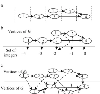
Example 1 Consider a sequential circuit S shown in Fig.1a, in which 1,2,3 and 4 are logic blocks, b,c,d, and e are L- registers, and a which is highlighted, is a Hold register. The topology graph G1of S is shown in Fig.1b.
Definition 2 A vertex in a directed graph is called as a sink vertex, if there is no outgoing edge from the vertex.
Responsible Editor: S. T. Chakradhar
* Debesh Kumar Das debeshd@hotmail.com
1 Computer Science and Engineering Department, Jadavpur University, Calcutta 700032, India
2 Faculty of Informatics, Osaka Gakuin University, Osaka, Japan J Electron Test
DOI 10.1007/s10836-015-5527-3
Journal of Electronic Testing: Theory and Applications, Vol.31, Issue 3, pp.321-327, June 2015.
Definition 3 The set of direct predecessors [successors] of any vertex u in a directed graph is denoted as pre(u) [suc(u)].
Definition 4 (Time-expansion graph (TEG)): Let S be an acyclic sequential circuit and let G = (V,A,r) be the topology graph of S. Let E = (VE, AE, t, l) be a directed graph, where VE is a set of vertices, AE is a set of arcs, t is a mapping from VE to a set of integers, and l is a mapping from VE to the set of vertices in G. If graph E satisfies the following five conditions, graph E is said to be a time-expansion graph (TEG) of G.
C1(Logic Preservation): The mapping l is a surjective, i.e., ∀v ∈V, ∃u ∈VEsuch that v=l(u)
C2(Input preservation): Let u be a vertex in E. For any direct predecessor v (∈ pre(l(u)) of l(u) in G, there exists a vertex u’ in E such that l(u’) = v and u’ ∈ pre(u). C3(Time consistency): For any arc (u,v) (∈ AE), there exists a corresponding arc (l(u),l(v)), and if r(l(u),l(v))
∈Z+, then r(l(u),l(v)) = t(v)-t(u), or else (r(l(u),l(v)) = h, t(u) < t(v).
C4(time uniqueness): For any pair of vertices u,v (∈VE), if t(u) = t(v) and l(u) = l(v), then the vertices u and v are identical, i.e., u = v.
C5(Hold consistency): For any pair of arcs (u1,v1), (u2,v2) (∈AE) such that (l(u1), l(v1)) = (l(u2), l(v2)) and r(l(u1), l(v1)) = r(l(u2), l(v2)) = h, if t(v1) > t(v2), then either t(u1) = t(u2) or t(u1) ≥ t(v2).
Example 2 Figure2ais a TEGs E1of the TG G (Fig.1b). The mappings t and l are shown in Fig.2bandcrespectively. Definition 5 A path from a vertex u1to ukin a TG G(V, A, r) [TEG E(VE, AE, t, l)] is obtained by concatenation of several arcs (u1,u2), (u2,u3),(u3,u4), (u4,u5),…….,(uk-1,uk) i, 1<i<(k- 1), where (ui, ui+1) ∈A [AE].
Definition 6 The length of an arc (vi, v2)∈ AEin a TEG E(VE, AE, t, l), denoted as len(v1,v2) is given by t(v2) –t(v1). Definition 7 The length of a path in a TEG is the summation of the lengths of the different arcs in it.
Definition 8 Given a TG G(V,A,r) let E(VE,AE,t,l) be any TEG of it, let p be a path from a vertex u1to ukin E obtained by concatenation of the arcs (u1,u2), (u2,u3), (u3,u4), (u4,u5),……., (uk-1,uk) i,1<i<(k-1), where (ui, ui+1) ∈A [AE]. The path p’ in TG from the vertex v1to vkin TG G passing through vertices (v1,v2, v3, …….,vk), where each vi= l(ui) is called as the corresponding path of p.
2.2 Time Expansion Model (TEM)
Definition 9 [6] Let S be an acyclic sequential circuit, let G = (V,A,r) be the topology graph of S, and let E = (VE, AE,t, l) be a TEG of G. The combinational circuit CE(S) obtained by the following procedure is said to be the time expansion model (TEM) of S based on E.
(1) For each vertex u ∈VE, let logic block l(u) (∈V) be the logic block corresponding to u.
(2) For each arc (u,v)∈AE, connect the output of u to the input of v with a bus in the same way as (l(u),l(v)) (∈A). Note that the connection corresponding to (u,v) has no register even if the connection corresponding to (l(u),l(v)) has a register (i.e., r(l(u),l(v))≠0).
(3) In each logic block, lines and logics that are reachable to neither other logic blocks nor primary outputs are removed.
Example 3 Figure3is a TEM of the sequential circuit S (Fig. 1a) based on TEG E1(Fig. 2a). The integer mapping t of E1is also shown.
a
b
1 2
3
4 a
b c d
e
2 4
1 3
h
1 1
2
Fig. 1 a The sequential circuit S b: The topology graph G1 of S
b
c
1 2 3 4
1 2
Vertices of E1
a
Set of integers
1 2 3 4
1 2
1 2 3 4
1 2
2 4
1 h 1 3
1 2 Vertices of E1
Vertices of G1
-4 -3 -2 -1 0
Fig. 2 a TEG of G1: E1 b: Mapping t from the vertices of TEG E1 of Fig.2atoaset of integers c: Mapping l from the vertices of TEG E1 of a to the vertices of TEG G of Fig.1b
Theorem 1 [6] Let S be an acylic sequential circuit, and let F be the set of faults in S. Let G = (V,A,r) be the TG of S. 1) A fault f ∈ F is testable (or irredundant) in S if and only if
there exists a TEG E of G such that the fault fe∈Fe, corresponding to f is testable in the TEM CE(S) based on E. 2) A test pattern for a fault fe(∈Fe) obtained using a TEM CE(S) can be transformed into a test sequence for the fault f (∈F) corresponding to fault fe.
From this theorem, we can see that test generation for an acyclic sequential circuit can be performed by using several different TEMs. Furthermore, since TEMs are fully combina- tional, a combinational test generator can be used for the test generation provided the test generator can deal with the mul- tiple faults. Given an acyclic sequential circuit S, if we can derive all TEMs obtained from it and find the tests for these TEMs using combinational test generator for multiple faults, then it is sufficient to obtain the set of test sequences to detect the faults in S. However, this test generator has not to generate the tests for all possible multiple faults in each TEM as it has to find out tests for only those multiple faults which are oc- curring in several identical blocks of the TEM.
3 Cover Relation
Definition 10 Let u is a vertex in TG G and let E(VE, AE, t, l) be any TEG of G. The cone subgraph E’ (E, u) of E with respect to u is defined as the maximal sub-graph of E in which uE[l(uE) = u] is the only sink vertex, i.e., there is no other vertex vEin E’, for which l(vE) = u.
Definition 11 [2] Let G = (V, A, r) be the TG of an acyclic sequential circuit S, and let E1(V1,A1,t1,l1) and E2(V2,A2,t2,l2) be arbitrary TEGs of G. Let s be any sink vertex in G. Let E’1(E1,s) = (V’1,A’1) [E’2(E2,s) = (V’2, A’2)] be the cone sub- graph of E1[E2] with respect to s, where V’1and A’1[V’2and
A’2] are respectively the set of vertices and arcs in E’1[E’2].
TEG E1is said to cover TEG E2if there exists a mapping m from V’1to V’2, such that for every s, (i) m(s1)=s2, where l1(s1)=l2(s2)=s (ii) if v2=m(v1), for v1∈V’1and v2∈V’2, then for any pair of vertices u1∈pre(v1) and u2∈pre(v2) if l1(u1)= l2(u2), then u2=m(u1).
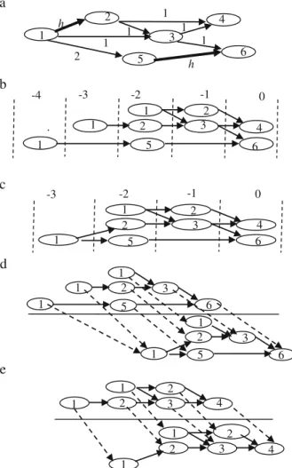
Example 4 Consider the TG G2of Fig.4a. Its two TEGs E2
and E3are shown in Fig.4bandcrespectively. E2covers E3 with the mapping shown in Fig.4dande.
Definition 12 Given a TG, if there exist two TEGs E1and E2
for it such that E1covers E2and E2covers E1, then E1and E2 are said to be equivalent.
Lemma 1 If E1 and E2be two TEGs of a TG G where E1 covers E2, then the test set generated for the TEM of E1 is sufficient to detect any fault in TEM of E2.
The above Lemma establishes the importance of finding the cover relations between the different TEGs of a given TG. Because, if we can find the set of minimum number of TEGs of a TG, that cover all possible TEGs of TG, then the test set generated from the TEMs corresponding to this set of TEGs is sufficient to detect the faults of all possible TEMs. From
1 2 3 4
1 2
-4 -3 -2 -1 0
Fig. 3 TEM of S based on E1 of Figs.2aandb
.
a
d
-2 -1 0
c -3
-3 -2 -1 0
b -4
e
2
1 3
h 1
1
6 1 5
1
2 h
4
1 2
5
2
3 4
6 1
1
1 2 5
2
3 4
1 6
1 2 5
3 6 1
1
1 2 5
3 1 6
1 2
2
3 4
1
1 2
2
3 4
1
1
Fig. 4 a TG G2 b: TEG E2 of G2 c: TEG E3 of G2 d: The mapping m with respect to sink node 6 e: The mapping m with respect to sink node 4
Theorem 1, this test set can be transformed to a set of test sequence to detect all faults in the sequential circuit.
Given two TEGs E1and E2for a TG G, to determine that whether E1covers E2, we have to find the mapping m, if exists as defined in Definition 11. The algorithm to find this cover relation is given in [2].
3.1 Maximum TEG
Definition 13 [2] Given a TG G, a TEG E which cannot be covered by any other TEG of G except by its equivalent TEG, is called a maximal TEG of G. If number of maximal TEGs is one, then that maximal TEG is called as the maximum. Definition 14 If a sequential circuit has a maximum TEG, then that circuit is max-testable.
If a sequential circuit S is max-testable, then by finding the test set of the TEM of its maximum TEG, we can generate the test sequence to detect all faults in S (Lemma 1 and Theorem 1). If a sequential circuit has a maximum TEG, how can we find out that? One method may be to draw all TEGs, and then find the maximum TEG among them that covers any other TEG and cannot be covered by anyone else. Obviously, this process is time consuming and impractical. The best way to achieve this is to draw it in such a manner such that it follows the properties of the maximum TEGs. The question is- while we achieve a TEG, is it easy to confirm whether this TEG is maximum or not? In some special cases, the features in a TEG clearly indi- cate whether it is maximum or not.
Lemma 2 [2] Given a TEG, if it has no re-convergent fanout, then it is maximum TEG.
Lemma 3 [2] Consider a hold arc h (h1, h2) in a TG G(V,A,r). Let E = (VE, AE, t, l) is a TEG of G. Consider two different vertices v1and v2∈VE, such that l(v1)=l(v2)=h2. If there exists a vertex u ∈VEsuch that l(u)=h1and u ∈pre(v1) and u
∈pre(v2), then E cannot be a maximum TEG.
Lemma 4 [2] Let a TEG E has re-convergent fan-outs. If for every such re-convergent fan-out, no path in the re-convergent loop contains an arc that corresponds to a hold arc in TG, then E is maximum.
Definition 15 Two paths p1and p2in a TG G(V,A,r) [TEG E(VE,AE,t,l)] are parallel to each other with respect to an arc (v1,v2) ∈A [AE] if both head and tail vertices of the two paths are same and the arc (v1, v2) is not common to both p1and p2. Theorem 2 Consider a TEG E(VE, AE, t, l) of a TG G(V, A, r). The necessary condition for E not to be maximum TEG, is that if there exists a pair of vertices u,v ∈VE, such that there are at
least two parallel paths p1 and p2between u and v, with respect to an arc (v1, v2), such that r(l(v1),l(v2)) = h.
After obtaing a TEG from a TG, we can easily confirm whether that TEG is maximum or not. If it is found to be maximum, we need not draw the other TEGs to compare them with it. But suppose we fail, i.e., given a TG we get a TEG E but find that it is not maximum. We then try to obtain another TEG. For a simple structured TG, it may not be a hard task to try for all other alternatives. But, for a complex structure with several hold registers and paths this may not be so easy. More- over, a TG may not have any maximum TEG. Thus, our ef- forts may be futile after searching of the different possibilities. The question is, by observing the TG can we confirm that whether this TG has a maximum TEG or not and if it has maximum TEG, how to obtain that in one chance.
4 The Properties of a Circuit to Have Maximum TEG If any arc (v1, v2) ∈ AEin a TEG E(VE, AE, t, l) of a TG G(V,A,r) is a non-hold arc, len(v1, v2) is always fixed and given by r(u1, u2), where u1=l(v1) and u2=l(v2). But if (v1, v2) corresponds to a hold arc what can be the value for len(v1,v2)? As a hold register can hold a value for arbitrary amount of time, this len(v1,v2) can be any value between 1 and infinity. But there are some restrictions as this length depends on the length of other paths, as evident from the following Lemma.
Lemma 5 Consider a TEG E(VE, AE, t, l) of TG G(V,A,r). Let there be two arcs (v1, v2) and (v’1, v’2) ∈ AEin the TEG, such that r(l(v1),l(v2))=r((l(v’1),l(v’2))=h, where h is a hold arc in G. For t(v2)<t (v’2), with d=t(v’2) - t(v2),
(i) If len(v’1, v’2) is chosen as any value k such that k > d, then len(v1, v2)=k-d,
(ii) If len (v1, v2) is chosen as any value k>0, then len(v’1, v’2) is either (a) between 1 and d or (b) k + d.
Given a TG, to have its maximal or maximum (if it exists) TEG, we have to draw the TEG in such a manner such that no hold-start vertex can lie in the predecessor of two hold-end vertices. If the TEG is maximal or maximum then the length of hold-arc cannot be always any arbitrary value.
Definition 16 Let u and v are two vertices in a TG, and there is a path p between them which does not contain any hold arc, then there exists a fixed length between u and v along the path p, which is given by the summation of the lengths of the different arcs along the path.
Definition 17 Consider a TG G(V,A,r) where (h1,h2) ∈A is a hold arc and u ∈V is a vertex reachable from h2. Let there be at least two paths from h2to u. Let in each TEG E(VE,AE, t,l) of G,
v1, v2and w ∈VE, are three vertices such that (i) l(v1)=l(v2)=h2
(ii) l(w)=u and (iii) t(v1)<t(v2). Let p1* [p2*] is the path from v1 [v2] to w in E and p1[p2] is the corresponding path in G. Let the path p3[p4] in TG is obtained by concatenation of hold arc (h1, h2) with p1[p2], then p3is unbounded with respect to the path p4. Example 5 Consider the TG of Fig.4a. The arc (1,2) is a hold arc. There are two paths from 2 to 4. In each TEG E(VE,AE, t,l) we may get three vertices v1, v2and w ∈ VE, such that (i) l(v1)= l(v2)=2 (ii) l(w)=4 and (iii) t(v1)<t(v2). Thus in the TG, the path 1-2-3-4 is unbounded with respect to path 1-2-4. Definition 18 In a TG, if an unbounded path exists with re- spect to a path p, then the path p is a bounded path in TG. Lemma 6 Consider a TG G(V,A,r) where (h1,h2) ∈A is a hold arc and w ∈V is a vertex reachable from h2. Let there be at least two non-hold paths from h2 to u having two different lengths. Then there exist
(i) one TEGs E1(VE1,AE1, t1,l1) having three different verti- ces u1, u2and u3in E1 with l1(u1)=h1, l1(u2)=l1(u3)=h2, and pre(u1)=pre(u2)=u1,
(ii) one TEGs E2(VE2,AE2, t2,l2) having four different verti- ces v1, v’1, v2, v3in E2 with l2(v1)=l2(v’1)=h1, l2(v2)= l2(v3)=h2, and pre(v1)≠pre(v2).
Definition 19 Suppose in a TG, p1is unbounded path with respect to bounded path p2. Then p2 has a bounded range given by a pair of positive integers (n1,n2) where n1≤n2. The values of n1and n2are obtained in such a manner such that in any TEG E(VE,AE, t,l) of TG G, for the pair of paths p1* and p2* in E with p1and p2respectively be the corresponding paths in G, if the length of the path p2* in E is any value between n1 and n2(both inclusive) with the condition that p1* and p2* has no common vertex v for which l(v)=h1. Example 6 Consider the TG of Fig.4a. The arc (1,2) is a hold arc. The path 1-2-3-4 is unbounded with respect to path 1-2-4. The path 1-2-4 is bounded by a range {2,2}.
Example 7 The topology graph G3is shown in Fig.5. The arc (1,2) is a hold arc. The path 1-2-3-4 is unbounded with respect to path 1-2-4. The path 1-2-4 is bounded by a range {2,4}. Lemma 7 Consider a hold arc (v1, v2) in a TG G(V,A,r), where r(v1, v2)=h. Let v is a vertex reachable from v2by two non-hold paths p1and p2with fixed lengths d1and d2respectively where
d1<d2, (let there is no other path from v2to v). Let is p’1[p’2] is the path from v1to v that includes p1[p2]. Then the following holds (i) the path p’1is a bounded path in G with a bounded range
{(d1+1), d2}
(ii) the path p’2is unbounded with respect to p’1.
Definition 20 If between two vertices u and v in a TG, there exists a bounded path p, bounded by a range {l,l’}, then there exists a bounded length lboundof p which equals to any integer value in the bounded range {l,l’} i.e., l≤lbound≤l’.
Example 8 The lboundof bounded path 1-2-4 of Fig.5is any value in the range {2,4}, i.e., 2≤lbound≤4.
If there are several bounded paths between u and v, there exist several bounded lengths between u and v, whose values d e p e n d o n h o w w e a s s i g n t h e m i n a p p r o p r i a t e bounded ranges.
Theorem 3 A TG G, has no maximum TEG iff u being the hold-start vertex, and between two vertices u and v in G, there exists one or more bounded paths, and whatever be the as- signment, the bounded length of a bounded path p becomes always equal to bounded or fixed distance of any other path p’ between u and v, where p and p’ are parallel to each other with respect to an arc (h1,h2) where r(h1,h2)=h.
Lemma 8 If a TG has no maximum TEG, then there exist two vertices u and v in TG, such that there are two paths between u and v, where one of them is bounded and the other is either bounded or fixed.
Lemma 9 If a TG has no maximum TEG, then there exist two vertices u and v in TG, such that there are at least three paths between u and v.
Example 9 The circuit of Fig.1ais max-testable as there are only two paths (Lemma 9).
Theorem 4 A TG G(V,A,r) is having a maximum TEG, iff (i) it has no bounded path, or
(ii) if for each bounded path p between two vertices, there exists a bounded length which is not equal to bounded or fixed length of any other path p’ between u and v, where
2 2 4
1 3 3
1
h 1 1
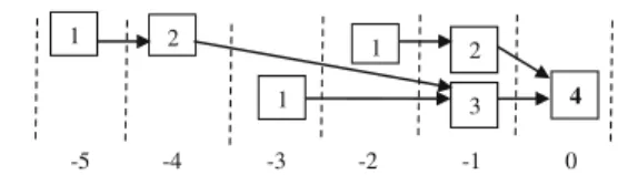
Fig. 5 TG G3
1 2
3 4
1 2
1
-5 -4 -3 -2 -1 0
Fig. 6 TEM of the max-testable circuit of Fig.5on which combinational test generation algorithm is to be run
p and p’ are parallel to each other with respect to an arc (v1,v2) where r(v1,v2)=h.
Example 10 The circuit corresponding to TG of Fig.4ais not max-testable, because the bounded length of the path 1-2-4 is equal to the fixed length of the path 1-3-4.
Example 11Consider the TG of Fig.5. Its path 1-2-4 has the bounded range {2,4}. There is another path 1-3-4 parallel to
1-2-4 with respect to hold arc (1,2). This path has a fixed length 3. Thus, we may assign the bounded length of 1-2-4 as 2 or 4 to satisfy the condition (ii) of Theorem 4. Hence the circuit corresponding to TG of Fig.5 is max-testable. The corresponding TEM is shown in Fig.6with integer mapping t of the maximum TEG.
The question is, even if a TG has a maximum TEG, how we can find out that. The following algorithm is given for that.
Algorithm to find maxtestability
for each sink vertex s in a TG G(V,A,r)
(i) Find the set H of hold-start vertices, s.t. for all uZH, there exists at least 3 paths to s and only two of which contain a common hold arc,
(ii) for each uZH
(a) find all the bounded ranges and fixed distances from u to s
(b) assign the bounded distances
(c) if bounded distance of a path p becomes equal to bounded or fixed distance of another path p’, where p and p’ has at least one uncommon hold arc, then try for another assignment in (b), if no other assignment exists, then report ‘not maximum’ and return
(d) Draw TEG with the assignment, it is maximum. Return.
5 Conclusion
We used time expansion model (TEM) to have the test sequences for acyclic sequential circuits. To obtain the TEMs of a sequential circuit, we used time expansion graphs (TEG). We identify a class of acyclic sequential circuits, called as max-testable class for which the test sequences can be easily achieved by running a combi- national test generation tool on a TEM of the circuit, obtained by finding a particular TEG called as maxi- mum TEG. The combinational test generator should have the capability of detecting multiple faults. We pre- sented an algorithm to find max-testable class of cir- cuits. Any acyclic sequential circuit with no hold regis- ter belongs to the max-testable class. A subset of the acyclic sequential circuits which have hold registers be- long to max-testable class. Given an acyclic sequential circuit, we presented an algorithm to determine whether it belongs to max-testable class or not and if it belongs to max-testable class we also find the TEM on which the test generator tool is to be run.
References
1. Balakrishnan A, Chakradhar ST (1996) BSequential circuits with combinational test generation complexity,^ Proc. of IEEE Int. Conf. on VLSI Design, 111–117
2. Das DK, Innoue T, Chakraborty S, Fujiwara H (2004) BMax-testable class of sequential circuits having combinational test generation complexity.^ Proc.of IEEE Asian Test Symposium, Taiwan, 342– 347
3. Fujiwara H (2000) A new class of sequential circuits with combina- tional test generational complexity. IEEE Transon Comput 49(9): 895–905
4. Fujiwara H, Iwata H, Yoneda T, Ooi CY (2008) A Non-scan design- for-testability for register-transfer level circuits to guarantee linear- depth time expansion models. IEEE Trans Comput Aided Des Integr Circ Syst 27(9):1535–1544
5. Gupta R, Gupta R, Breuer MA (1990) The BALLAST methodology for structured partial scan design. IEEE Transon Comput 39(4):538– 544
6. Innoue T, Das DK, Sano C, Mihara T, Fujiwara H (2000) BTest generation of acyclic sequential circuits with hold registers.^ Proceedings of the IEEE/ACM International Conference on Computer-Aided Design, 550–556
7. Inoue T, Hosokawa T, Mihara T, Fujiwara H (1998) "An optimal time expansion model based on combinational test generation for
RT level circuits." Proceedings of IEEE Asian Test Symposium, 190–197
8. Kim YC, Agrawal VD, Saluja KK (2005) Combinational automatic test pattern generation for acyclic sequential circuits. IEEE Trans Comput Aided Des Integr Circ Syst 24(6):948–956
9. Takasaki T, Innoue T, Fujiwara H (1998) BPartial scan design methods on internally balanced structure,^ Proceedings of the IEEE Asia and South Pacific Design Automation Conference, 211–216
Debesh Kumar Das received the B.E. and M.E. degrees in Electronics and Tele-communication Engineering from Jadavpur University, India, in 1982 and 1984 respectively. He did his PhD in Engineering from same University in 1997. He is presently Professor in Computer Science and Engineering Department of Jadavpur University. Previously, he also taught in Birla Institute of Technology, Mesra and University of Calcutta. His research interests include VLSI testing, logic synthesis, design for testability, built-in self-test and quantum computing. He is a member of the IEEE. He published more than 80 papers in International Journals and reputed conferences.
Hideo Fujiwara received the B.E., M.E., and Ph.D. degrees in electronic engineering from Osaka University, Osaka, Japan, in 1969, 1971, and 1974, respectively. He was with Osaka University from 1974 to 1985 and Meiji University from 1985 to 1993, Nara Institute of Science and Technology (NAIST) from 1993 to 2011, and retired from NAIST in 2011. Presently he is Professor Emeritus of NAIST and Professor at Faculty of Informatics, Osaka Gakuin University, Japan. His research interests are logic design, digital systems design and test, VLSI CAD and fault tolerant computing, including high-level/logic synthesis for test- ability, test synthesis, design for testability, built-in self-test, test pattern generation, parallel processing, and computational complexity. He has published over 390 papers in refereed journals and conferences, and nine books including the book from the MIT Press (1985) entitled BLogic Testing and Design for Testability.^ He received many awards including IEEE Computer Society Meritorious Service Awards in 1996 and 2005, IEEE Computer Society Continuing Service Award in 2005, and IEEE Computer Society Outstanding Contribution Awards in 2001 and 2009. Prof. Fujiwara is a life fellow of the IEEE, a Golden Core member of the IEEE Computer Society, a fellow of the IEICE (the Institute of Electron- ics, Information and Communication Engineers of Japan) and a fellow of the IPSJ (the Information Processing Society of Japan).