T his doc ument is downloaded at: 2018-03-23T 18:07:41Z
T itle
二重翼列波力タービンの性能特性
A uthor(s )
吉田, 光弘; 黒川, 由美; 奥村, 哲也; 林, 秀千人; 瀬戸口, 俊明; 濱川, 洋
充
C itation
長崎大学大学院工学研究科研究報告, 48(90), pp.15-22; 2018
Is s ue D ate
2018-01
UR L
http://hdl.handle.net/10069/37933
R ig ht
NA O S IT E : Nag as aki Univers ity's A c ademic O utput S IT E
二 重 翼 列 波 力 タ
ン
性 能 特 性
光 弘
*黒
美
**奥 村 哲 也
*林 秀 千 人
*瀬 戸 口 俊 明
***濱
洋 充
****Performance of Double Rotor Turbine for wave power generator
by
Mitsuhiro YOSHIDA*, Yumi KUROKAWA**, Tetsuya OKUMURA*, Hidechito HAYASHI*
Toshiaki SETOGUCHI***, Hiromitsu HAMAKAWA****
It is proposed the new type turbine for OWC that consists of Wells and Impulse rotors. Wells and impulse rotors are set concentrically for both high efficiency and starting characteristics. This paper presents the concept of the turbine and some geometrical variation with the numerical simulations in steady flow condition; hub ratio, split duct length and sweep blade. The maximum efficiency is obtained at the low flow coefficient that is fitted to the high -speed operation. The variation of efficiency with flow coefficient is small for large flow coefficient that advantages to the starting characteristics. The maximum efficiency is large at small hub ratio for the flow rate of wells turbine part decreased. The swept blade is not fit for the impulse rotor. The split duct is designed to fit the flow coefficient at the maximum efficiencies of Wells and Impulse turbines. It is pointed out that the geometry of the split duct is important to improve the turbine performance.
Key words : Wells Turbine, Impulse Turbine, Wa ve P ower Genera tion, Wa ve Energy, OWC
1 . 諸 言
近 わ 国 や 欧 中 心 ,海 洋 ネ 利 用
進 い . 一 種 あ 振 動 水 柱 型
OWC:Oscillating Water Column 波 力 発 電 動
部 直 接 海 水 触 い , ン ン 優 ,
風 突 発 的 現 象 対 応 能 あ
利 点 , 多 く 研 究 い .
発 電 方 法 波 浪 ネ 往 復 空 気 流 変
換 , 往 復 空 気 流 中 常 一 方 向 回 転 特 殊
タ ン 用 い 電 気 ネ 変 換 .タ ン
, 多 く 用 い タ ン
, 近 注 目 い 衝 動 タ ン 中 心 あ ,
い く 試 い .
タ ン 原 理 ,低 流 量 係 数 時 高 い 動
力 得 高 速 型 特 性 あ . , 強 度 ,
保 , 音 問 題 視 い . 起 動 や 高
流 量 係 数 時 ,タ ン 失 速 ネ 効 率
極 端 低 状 態 至 . ,流 量 変
動 対 定 い 問 題 点
(1)~(12)
. 一 方 ,
衝 動 タ ン タ ン 比 高 い
高 流 量 係 数 時 広 範 比 較 的 高 い 効 率 得 ,
起 動 特 性 優 い . ,低 流 量 係 数 時 効
率 急 激 低 く ,最 大 効 率 タ ン
劣 い
(13)~(22)
.
特 性 踏 え , タ ン 高 流
量 係 数 時 性 能 改 善 , 衝 動 タ ン タ
タ ン 利 用 試 い
(23)
.
う ,二 タ ン 設 置 接 続 形 状 ,
複 雑 化 伴 い 設 備 費 用 や 維 持 管 理 費 用 増 加 恐
あ . ,再 生 能 ネ 用 い 発 電
成29年12 25日 受 理
長 崎 大 学 工 学 研 究 科 Dept. engineering, Nagasakiuniversity
西 日 本 流 体 技 研 株 式 会 社 WEST JAPAN FLUID ENGINEERING LABORATORY Co.,Ltd.
*** 佐 賀 大 学 Saga university
二重翼列波力タ ン 性能特性
Split duct
Impulse turbine
Wells turbine Casing
d0 dw dh di
方 法 好 く い .
著 者 両 タ ン タ ン
組 入 一 体 化 ,起 動 性 効 率 向 考 慮
ン 構 造 新 い 波 力 タ ン 、 わ 二 重
翼 列 波 力 タ ン 提 案 .本 研 究 ,数 値
ュ ョ ン 定 常 流 特 性 ,
タ ン 単 体 , 衝 動 タ ン 単 体 比 較 評 価 .
, タ ン 部 衝 動 タ ン 部
チ ン 観 点 , 形 状 影 響 調 .
記 号 表
AR : 翼 面 積 (AR
spanChord
Number
) [m2]CT : ト ル ク 係 数 (
a
R a v TR A U V
T C
2 2
2
)
d0 : タ ー ビ ン 外 径 [m]
dh : ハ ブ 直 径 [m]
di : 衝 動 タ ー ビ ン 部 直 径 [m]
dw : 仕 切 り 板 入 口 直 径 [m]
P : 圧 力 [Pa]
Ra v : 平 均 半 径 [m]
T : ト ル ク [N・m]
U : 周 速 度 ( •
2 0 d
U ) [m/s]
V : 流 速 [m/s] : 流 量 係 数 (
U Va
)
: 効 率 ( )
: 角 速 度 [rad/s]
添 え 字
a : 回 転 軸 方 向
max: 最 大 効 率 点
r : 半 径 方 向
t : 周 方 向
∞ : 上 流 遠 方
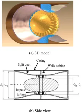
. 二 重 翼 列 波 力 タ ン 概 略
1 本 研 究 提 案 二 重 翼 列 波 力 タ ン 概
略 示 . 羽 根 車 , タ ン 衝 動
タ ン タ ン 羽 根 車
あ . 1(a) タ ン D ,
1(b) 側 面 見 断 面 示 . タ ン
衝 動 タ ン ,単 体 形 状 参 考
羽 根 形 状 設 計
(1),(2)(9),(14),(15),(20),(23)
.
(a) 3D model
(b) Side view
Fig. 1 Schematics of double impeller
タ ン 部 衝 動 タ ン 部 区
仕 洞 設 い .仕 洞 , 後 述 う
両 羽 根 車 最 適 流 量 係 数 わ 決 定 .
. 仕 洞 形 状
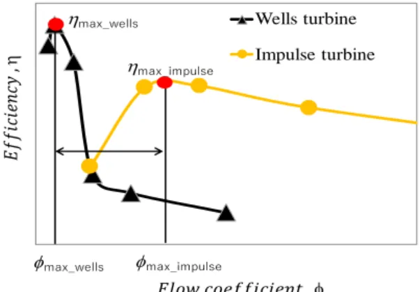
2 タ ン 衝 動 タ ン 効 率 曲 線
例 示 . タ ン 高 速 型 あ ,
最 高 効 率 流 量 係 数 小 い .一 方 ,衝 動 タ
ン 低 速 性 能 良 い ,最 高 効 率 示 流 量
係 数 大 い . う ,最 高 効 率 流 量 係 数 大
く 異 羽 根 車 納 ,次
2 工 夫 施 .
. タ ン ,最 高 効 率 衝 動 タ ン
低 流 量 あ , 周 方 向 速 度 大 く 半
径 大 い 側 設 置 ,衝 動 タ ン 周 方 向
速 度 小 い 内 側 設 置 .
. タ ン 最 高 効 率 流 量 係 数 う
軸 流 速 度 , 衝 動 タ ン 側 軸 流 速
度 大 く , タ ン 側 軸 流 速 度
小 く . わ ,衝 動 タ ン 側 縮 流 ,
タ ン 側 拡 大 流 , 羽 根 車 入
流 制 御 .
二 点 実 現 ,以 処 置 施 .
タ ン 直 径 d0,衝 動 タ ン di
, 流 量 係 数max_wells,max_impulse 比
次 う .
•
a V d P
T
2 0 4
0 _ _ _ 0 _ max_ max_ d d V V d V d V i impulse a wells a i impulse a wells a impulse wells • (1)
, 周 方 向 速 度 Vt_wells=d0/2×,
Vt_impulse=di/2× あ . タ ン 部 衝 動
タ ン 部 直 径 比 d0/di = 1:0.7 ,
タ ン 入 軸 流 速 度 , 表1
2 . 0 7 . 0 0 . 1 75 . 0 10 . 0 0 max_ max_ _ _ • • i impulse wells impulse a wells a d d V V (2)
, 最 高 効 率 流 量 係 数 対 応
タ ン 軸 流 速 度 異 わ . ,
仕 洞 設 流 量 制 限 , 減 速 増 速
行 い タ ン 入 軸 流 速 度 式(2) わ .
2 , 流 部 軸 流 速 度 一 定Va
∞ ,
タ ン 部 衝 動 タ ン 部 , 連 続
関 係 次 式 成 立 .
2 2
0 _ 2 2 0 4
4 w a wells i
a d d V d d
V (3)
2 2
_ 2
4
4 w a impulse i h
a d V d d
V (4)
タ ン ハ 比dh/d0=0.5 , 式(2),(3),(4)
, 次 式 得 , 仕 洞 直 径dw 定 .
1 . 1 1 2 . 0 1 2 0 2 0 2 0 2 0 d d d d d d d d i h i w (4)
以 ,二 重 翼 列 タ ン 径 d0=300mm
.仕 洞 直 径 式(4) ,縮 流 等 影 響
考 慮 dw=280 mm,衝 動 タ ン 部 直 径di=200mm, ハ 直 径 dh=140mm . ,仕 洞 厚
5 mm あ .
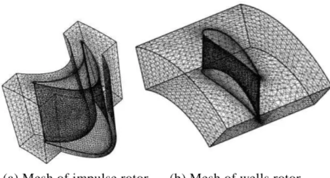
. ュ ョ ン 条 件
タ ン 定 常 状 態 特 性 ュ ョ
ン 解 析 . 3 ュ ョ ン 領 域 示
. 3(a) 全 体 概 要 あ .計 算 1 チ
行 . タ ン 直 径 300mm 対 , 全 長
4000mm あ . タ ン 衝 動 タ
ン タ 部 回 転 領 域 設 定 . 回 転
領 域 静 止 領 域 間 イ ン タ Stage 設
定 . 入 口 境 界 流 速15m/s 一 様 流 側 設 定 ,
流 境 界 い ,大 気 圧 設 定 . 3(b) 衝 動
タ ン タ イ ベ ン 示
い . イ ベ ン 羽 根 二 次 元 板26枚 成
立 い . タ 反 角 流 入 流 出 角 60
度 ,30枚 構 成 い (14),(15),(20),(21). 3(c)
タ ン 1 チ 回 転 領 域 示 い
Fig. 2 Efficiency curves of wells turbine and impulse turbine.
Table 1 Maximum efficiency points of two turbines
max at max max
Wells turbine 0.10 0.64 Impulse turbine 0.75 0.48
(a) Overall regions
(b) Impulse rotor (c) Wells rotor Fig. 3 Schematics of one pitch simulation regions
二重翼列波力タ ン 性能特性
(a) Mesh of impulse rotor (b) Mesh of wells rotor Fig.4 Mesh of rotor regions of double rotor
Table 2 Mesh number for each part 1 pitch parts No. of Elements
Wells turbine part 121988 Impulse turbine part 102430 Total parts 394721
.羽 根 NACA0021翼 型 対 称 翼 ,翼 弦 長90 mm,
ハ 比0.7 あ . 羽 根 枚 数 6枚 あ
(1),(2),(9)
.
4 タ 部 ュ 状 況 示 . ,
表2 要 素 数 示 い . 4(a) 衝 動 タ ン
タ 部 あ 翼 表 面 イ ン ョ ン
設 定 い .第1層 厚 0.1 mm ,5層 設 定
い . 衝 動 タ ン 部 要 素 数 約10万 全 体 あ .
4(b) タ ン タ 部 あ .
場 ,翼 表 面 第1層 厚 0.2 mm ,7層 イ ン
ョ ン 設 定 い . タ ン 部
要 素 数 12万 ,全 体 四 面 体 要 素 ,
39万 要 素 ,両 タ ン 以 衝 動 タ
ン イ ベ ン 仕 洞 部 要 素 数
多 く い .
. 結 果 考 察
5.1従 来 タ ン 比 較
5 , 二 重 翼 列 タ ン , , 衝 動 タ
ン 単 性 能 比 較 い . 5(a)
特 性 あ . 流 量 係 数 増 加 , い
タ ン 係 数 増 加 い .特 ,衝 動 タ
ン 増 加 著 く , タ 回 転 遅 く 流 量 多
く 流 大 流 量 係 数 特 性 良 示 い .
比 , タ ン 流 量 係 数 増 加
あ 大 く い . , 両 タ ン 起 動 特 性
違 い あ .一 方 ,二 重 翼 列 タ ン ,衝 動 タ
ン 多 少 低 い , 係 数 増 加 大
く , 起 動 特 性 良 好 あ わ . , 低 流
量 係 数 , 高 速 回 転 無 次 元 化 係 数
小 い , タ ン 場 , 最 高
効 率 点 付 近 5(b)参 照 若 大 く
い . あ 明 確 い , 衝 動 タ ン
係 数 小 く . 比 二 重
翼 列 タ ン , タ ン 若 低 い
, 衝 動 タ ン う 極 端 低 い 値
, 十 発 揮 い . 5(b)
効 率 流 量 係 数 変 化 示 い . 衝 動 タ
ン 流 量 係 数 0.75付 近 最 高 効 率 0.48程 度 示
い . 一 方 , タ ン ,0.63く い
大 値 い . , 流 量 係 数 増 加
流 量 係 数 0.2 付 近 急 効 率 低 , 運
転 範 非 常 く い わ .
比 ,二 重 翼 列 タ ン 最 高 効 率 0.36程 度 ,
両 羽 根 車 比 低 い 値 あ . , 最 高 効 率
タ ン 同 様 低 流 量 あ , 高 速 回 転 適
い わ . , 流 量 係 数 変 化
緩 や ,流 量 係 数 作 動 変 化 ,最 高
効 率 低 除 く ,良 い 特 性 示 い い え .
(a) Torque curves
(b) Efficiency curves
Fig, 5 Comparison of performance curves of double rotor turbine with wells and impulse turbines
0.0 0.2 0.4 0.6 0.8
0.0 0.2 0.4 0.6 0.8 1.0 1.2 1.4
E
ffi
ci
en
cy
Flow coefficient
with each turbine
Wells turbine
Impulse turbine
double rotor turbine hub ratio 0.7
0.0 1.0 2.0 3.0 4.0 5.0
0.0 0.2 0.4 0.6 0.8 1.0 1.2 1.4
T
o
rrq
u
e
co
effi
ci
en
t
CT
Flow coefficient
with impulse rotor hub ratio
Double rotor turbine Impulse turbine Wells turbine
hub ratio 0.7
0.0 2.0 4.0
0.0 0.2 0.4 0.6 0.8 1.0 1.2 1.4
T
o
rq
u
e
co
eff
ic
ie
n
t
CT
Flow coefficient hub ratio 0.7 hubratio 0.5
Wells rotor : : hub ratio 0.7 Impulse rotor:
0.0 0.1 0.2 0.3 0.4 0.5
0.0 0.2 0.4 0.6 0.8 1.0 1.2 1.4
E
ffi
ci
en
cy
Flow coefficient with impulse rotor hub ratio
hub ratio 0.7 hub ratio 0.5
Wells rotor : : hub ratio 0.7 Impulse rotor:
0.0 0.5 1.0 1.5 2.0
0.0 0.2 0.4 0.6 0.8 1.0 1.2 1.4
F
lo
w
ra
ti
o
qw /qi
Flow coefficient with impulse rotor hub ratio
hub ratio 0.5 hub ratio 0.7
Wells rotor :
: hub ratio 0.7 Impulse rotor:
design condition
5.2 面 積 比 の 影 響
6 衝 動 タ ン 側 ハ 比 変 更
模 式 あ . 6(a) 衝 動 タ ン 側 ハ 比
タ ン 同 0.7 設 定 場 あ . 一
方 , 6(b) 衝 動 タ ン ハ 比 0.5 , 衝
動 タ ン パ ン 大 く あ .
, 衝 動 タ ン 側 縮 流 押 え
予 想 .
7 性 能 比 較 あ . 中 赤 記 号 ハ 比
0.5 パ ン 長 く あ . 7(a)
係 数 ,流 量 係 数0.5付 近 低 流 量 係 数 ,
ハ 比 影 響 あ 見 い , 大
流 量 係 数 , パ ン 長 い ハ 比 0.5 場 若
低 く い . , 7(b) 効 率 い , 最
高 効 率 高 く , 大 幅 改 善 見 . ,
最 高 効 率 流 量 係 数 0.35付 近 大 く , ハ 比0.7
い く ぶ 低 速 型 い . 最 高 効 率 大
流 量 係 数 , 効 率 ゆ や 減 少 示 , 高 い
状 況 保 い .
8 タ ン 流 入 流 量 衝 動 タ
ン 流 入 流 量 比 示 い . 章 示
う , タ ン 入 流 量 割
最 高 効 率 流 量 う う 設 定 .
, 中 破 線 示 あ , ハ 比0.7 場
比 1.0以 , 設 計 大 く 離
い . タ ン 流 流 量 設 計 大
く 異 , 低 い 効 率 作 動 特 性 . 一 方 , ハ
比 0.5 パ ン 大 く , 羽 根 入
流 速 小 く , 衝 動 タ ン 側 負 荷 減 .
結 果 , タ ン 側 流 込 減 少 ,
(a) hub ratio 0.7
(b) hub ratio 0.5
Fig.6 Geometries of hub ratios of impulse rotor
流 量 比 約 半 程 度 減 少 設 計 近 い
あ . , 設 計 離 い .
5.3 衝 動 タ ン 形 状 影 響
9 衝 動 タ ン 傾 変 更 示
い . 9(a) 30度 sweep角 度 付 ,
9(b) 0度 場 あ . 両 ,Sweep
角 度 以 同 形 状 い .
10 性 能 比 較 示 い . 10(a)
係 数 流 量 係 数 変 化 示 い .Sweep30
model 比 ,sweep0 model 係 数 若 大
く い , 両 者 違 い あ 見 い .
(a) Torque curves
(b) Efficiency curves
Fig, 7 Comparison of performance curves of double rotor turbine with hub ratio
二重翼列波力タ ン 性能特性
0.0 1.0 2.0 3.0 4.0 5.0
0.0 0.2 0.4 0.6 0.8 1.0 1.2 1.4
T
o
rrq
u
e
co
effi
ci
en
t
CT
Flow coefficient
with impulse rotor hub ratio
Sweep30 model Sweep0 model
hub ratio 0.7 in both rotors Impulse rotor:
geometry changed
0.0 0.1 0.2 0.3 0.4 0.5
0.0 0.2 0.4 0.6 0.8 1.0 1.2 1.4
E
ffi
ci
en
cy
Flow coefficient
with impulse rotor geometry
Sweep30 model Sweep0 model
hub ratio 0.7 in both rotor Impulse rotor:
geometry changed
0.0 0.5 1.0 1.5 2.0
0.0 0.2 0.4 0.6 0.8 1.0 1.2 1.4
F
lo
w
ra
ti
o
qw /qi
Flow coefficient
with impulse rotor hub ratio
Sweep0 model Sweep30 model
Wells rotor :
: hub ratio 0.7 Impulse rotor:
design condition
起 動 時 低 回 転 時 大 得
. 10(b) 効 率 示 い .Sweep30 model 比 ,sweep0 model 最 高 効 率 大 く 増 加
い . , 流 量 係 数 0.3程 度 い .
, 流 量 増 加 , 効 率 緩 や 減 少
, い 流 量 係 数 効 率 高 く い .
う ,sweep0 model 効 率 良 好
状 況 あ , 羽 根 車 次 元 化 , 必 性 能 向
当 い .
11 タ ン 衝 動 タ ン 流 量 比
(a) Sweep30 model (b) Sweep0 model Fig.9 Impulse rotor geometries
(a) Torque curves
(b) Efficiency curves
Fig.10 Comparison of performance curves of double rotor turbine with impulse rotor sweep angle
示 い .Sweep0 model ,Sweep30 model
異 布 示 い . 流 量 係 数 減 少
流 量 比 小 く い . , 低 流 量 係 数
い タ ン 流 , 設 計 近 く
示 , 最 高 効 率 増 加 招 い い .
, 設 計 流 量 比 大 く , 依 然
タ ン 流 込 大 く , 良 好 運 転
状 態 至 い い 示 い .
タ ン 較 , 衝 動 タ ン タ ン 負 荷 大
く , 前 後 圧 力 差 増 加 , 負 荷 小 い
タ ン 流 込 傾 向 あ . 点 踏
え タ ン 開 発 行 う 必 要 あ .
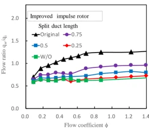
5.4 仕 洞 長 影 響
12 仕 洞 長 変 化 場 様 子 模
式 的 示 い . 長 0.75 倍 ,0.5
倍 ,0.25倍 ,0 倍 . 形 状 , 同
途 中 形 状 あ , 長 変 化
タ ン 側 流 入 面 積 変 化 い .
13 タ ン 衝 動 タ ン 区 別
仕 洞 長 , 性 能 特 性 影 響 示
い . 13(a) 係 数 変 化 表 い .流 量
係 数 大 い , 仕 洞 長 い
係 数 多 少 大 く 傾 向 あ . 13(b) 効 率 変
化 示 い .仕 洞 長 短 く ,
最 高 効 率 変 化 , 長 0.5倍
Fig. 11 Variation of flow ratio distributions for two impulse rotor geometries
Fig. 12 Variation of split duct length
0 Radial
direction 30
degree
0.0 1.0 2.0 3.0 4.0 5.0
0.0 0.2 0.4 0.6 0.8 1.0 1.2 1.4
T
o
rrq
u
e
co
effi
ci
en
t
CT
Flow coefficient
with Split duct legth
Original 0.75
0.5 0.25
W/O
Split duct length Improved impulse rotor
0.0 0.1 0.2 0.3 0.4 0.5 0.6
0.0 0.2 0.4 0.6 0.8 1.0 1.2 1.4
E
ffi
ci
en
cy
Flow coefficient
with Split duct legth
Original 0.75
0.5 0.25
W/O
Split duct length
0.25倍 い , 効 率 最 高 く0.5程 度 あ
. 一 方 , 流 量 係 数 0.5付 近 落 込 発 生
い . , 仕 洞 違 い ,
タ ン 部 流 込 流 状 況 変 化 ,
流 込 流 タ ン 流 及
影 響 変 化 ,0.5倍 0 倍
最 高 効 率 得 流 量 係 数 タ ン 部 衝 動
タ ン 部 離 い , 結 果 的 両 効 率 低 い
表 い あ .
14 流 量 比 示 い . 較 ,
長 短 く ,流 量 比 小 く い .
, 流 量 係 数 小 い ,0.5倍 短 い
仕 洞 流 量 比 あ 変 わ い . 最 高 効 率 示
低 流 量 部 , 仕 洞 長 い 場 , 流 量 係
数 流 量 比 減 少 傾 向 あ , 流 量 比
違 い , 若 小 く い . 傾 向 効 率
密 接 関 係 あ 明 確 い , 流 重 要
(a) Torque curves
(b) Efficiency curves
Fig.13 Comparison of performance curves of split duct length
Fig. 14 Variation of flow ratio for split duct length
役 割 果 い . 点 , 仕 板 短
, 流 改 善 重 要 あ .
6 . 結 論
波 力 発 電 用 タ ン , 起 動 性 効 率 向
, 二 重 翼 列 タ ン 提 案 , 特 性
ュ ョ ン 調 , 以 結 果 得 .
1. 起 動 対 応 高 流 量 係 数 大 比 較
的 良 好 効 率 特 性 得 .
2. 最 高 効 率 あ 大 く い , 低 流 量 係 数 最
高 効 率 得 , 高 速 型 タ ン
.
3. ハ 比 変 化 , タ ン 流 量
割 抑 え , タ ン 効 率
.
4. 仕 洞 長 短 く , タ ン
流 量 割 抑 え , タ ン 効 率
.
参 考 文 献
(1) 高 尾 ,”波 力 発 電 用 タ ン 性 能 及
次 元 形 状 翼 影 響)”,日 本 機 械 学 会 流 体 工 部
門 講 演 論 文 集(2014.10)
(2) 高 尾 , 瀬 戸 , 奥 原, 次 元 形 状 翼
タ ン , 日 本 機 械 学 会 流 体 工 部 門 講 演 論 文
集,0915(2012.11),pp 361-362
(3) 鈴 木,荒 , タ ン 翼 形 状 流 場
影 響 タ ボ 機 械, 35(2)(2007), pp24-29.
(4) R.Starzmann,T.Carolus,,Model-based selection of full- scale Wells turbines for ocean wave energy conversion and prediction of their aerodynamic and acoustic
0.0 0.5 1.0 1.5 2.0
0.0 0.2 0.4 0.6 0.8 1.0 1.2 1.4
F
lo
w
ra
ti
o
qw /qi
Flow coefficient
with Split duct legth
Original 0.75
0.5 0.25
W/O
二重翼列波力タ ン 性能特性
performances, J. Power and Energy 2014, Vol 228(1), 2
–16
(5) S.Shaaban,A.A.Hafiz,Effect of duct geometry on Wells turbine performance, Energy Conversion and Manage- ment 61 (2012) 51–58
(6) M.H.Mohamed,G.Janiga,E.Pap,D.Thévenin, Multi- objective optimization of the airfoil shape of Wells turbine used for wave energy conversion,Energy 36 (2011)438-446
(7) M.Torresi,S.M.Camporeale,G.Pascazio,Detailed CFD Analysis of the Steady Flow in a Wells Turbine Under Incipient and Deep Stall Conditions,Journal of Fluids Engineering,2009.7,Vol.131/071103,1-17
(8) P.Halder,A.Samad,D.Thevenin,Improved design of a Wells turbine for higher operating range,Renewable Energy 106 (2017) 122-134
(9) M.Takao,T.Tsunematsu, H.Katsube, S.Okuhara, M.M.A.Alam, T.Setoguchi,Numerical Simulation of Wells Turbine with 3D Blades, Proc. 6th Asian Joint Workshop on Thermophysics and Fluid Science, 2016.9,1-5
(10) A.Thakker,R.Abdulhadi,Effect of Blade Profile on the Performance of Wells Turbine under Unidirectional Sinusoidal and Real Sea Flow Conditions, International Journal of Rotating Machinery, Volume 2007,1-8 (11) Z.Taha, Sugiyono,T.Sawada,A comparison of
computational and experimental results of Wells turbine performance for wave energy conversion, Applied Ocean Research 32 (2010) 83-90
(12) K.Takasaki,T.Tsunematsu,M.Takao,M.M.A.Alam, T. Setoguchi, Wells Turbine for Wave Energy Conversion -Effect of Trailing Edge Shape-,The 13th Asian International Conference on Fluid Machinery, AICFM13-218(2015.9),1-6
(13) 高 尾 , 鈴 木 , 佐 藤 , 永 , 豊 , 瀬 戸 口 , 波 力
発 電 用 衝 動 タ ン 実 海 域 試 , タ ボ 機 械 ,
Vol.36, No.12 (2008) ,pp766-772
(14) 瀬 戸 口 , 高 尾 , 木 , 金 子 , 井 , 波 力 発 電 用
衝 動 一 ン 関 研 究 , 日 本 機 械 学 会 論 文 集
(B),65巻629 号(1991),pp255-261
(15) 高 尾 , ン 波 力 発 電 用 衝
動 タ ン,[No06-1]日 本 機 械 学 会2006 度 次 大 会 講 演 論 文 集,231-232
(16) A.Thakker,Z.Usmani,T.S.Dhanasekaran,Effects of turbine damping on performance of an impulse turbine for wave energy conversion under different sea
conditions using numerical simulation techniques, Re newable Energy 29 (2004) 2133–2151
(17) A.Thakker,T.S.Dhanasekaran,Computed effects of tip clearance on performance of impulse turbine for wave energy conversion, Renewable Energy 29 (2003) 529–547
(18) R.Badhurshah,A.Samad,Multiple surrogate based optimization of a bidirectional impulse turbine for wave energy conversion,Renewable Energy 74 (2015) 749-760
(19) B.Pereiras,F.Castro,A.Marjani,M.A.Rodríguez, An improved radial impulse turbine for OWC, Renewable Energy 36 (2011) 1477-1484
(20) 高 尾 ,波 力 発 電 用 イ ン 衝 動 型 タ ン 性 能
及 タ 形 状 影 響 ,日 本 機 械 学 会 流 体 工
部 門 講 演 論 文 集,2014.10.25 -26, 富 山
(21) Takao,H.Sato,M.M.A.Alam,S.Okuhara,G.Masaki, T. Setoguchi, A TWIN UNIDIRECTIONAL IMPULSE TURBINE FOR WAVE ENERGY CONVERSION- EFFECT OF ROTOR BLADE PROFILE ON THE PERFORMANCE -,AJK2015-1573,968-971
(22) K.Ezhilsabareesh,S.H.Rhee,A.Samad,Shape optimiza- tion of a bidirectional impulse turbine via surrogate models, Engineering Applications of Computational Fluid Mechanics, 2018,VOL.12,NO.1,1–12
(23) 高 尾 ,高 崎 ,奥 原 ,高 見 ,瀬 戸 口, 波 力 発 電 用
タ ン(性 能 及 タ 直 径) ,日
本 機 械 学 会 流 体 工 学 部 門 講 演 会 論 文 集(2014.10)