On the Acceleration of Test Generation
Algorithms
HIDEO FUJIWARA, SENIOR MEMBER, IEEE, AND TAKESHI SHIMONO, STUDENT MEMBER, IEEE
Abstract-In order to accelerate an algorithm for test generation, it is necessary to reduce the number of backtracks in the algorithm and toshorten the process time between backtracks. In this paper, we consider several techniques to accelerate test generation and present a newtest generation algorithm called FAN (fan-out-oriented test generationalgorithm). It is shown that the FAN algorithm is faster andmoreefficient than the PODEM algorithm reported by Goel. We also presentanautomatic testgeneration system composed of the FAN algorithm and the concurrent fault simulation. Experimental results onlarge combinational circuits of up to 3000 gates demonstrate that the systemperforms test generation very fast and effectively.
Index Terms-Combinational logic circuits, D-algorithm, decision tree, multiple backtrace, PODEM algorithm, sensitization, stuck faults,testgeneration.
I. INTRODUCTION
W5|
ITH the progressof LSI/VLSI technology, the prob- lem of fault detection for logic circuits is becoming more and more difficult. Asthe logic circuits under test get larger, generating tests is becoming harder. Recent work has established that the problem of test generation, even for monotonecircuits, is NP-complete [ 1].Hence, it appears that thecomputation is,for the worst case, exponential with the size of the circuit. One approach to overcome this is to take several techniques known as design for testability. The techniques usingshift registerssuch as LSSD [2], Scan Path [3], etc., allow the testgeneration problemtobecompletelyreduced to oneofgeneratingtestsfor combinational circuits. Hence, for theseLSSD-type circuits,it issufficienttodevelopafast and efficient test generation algorithm only for combinational circuits.Many testgeneration algorithms have been proposed over the years [4]-[8], [11].The most widely used is the D-algo- rithmreported by Roth [5]. However,it has been pointed out thattheD-algorithmisextremelyinefficient in generating tests for combinational circuits that implement error corr&ction and translation functions. Toimprove this point, a new test gen- erationalgorithmcalled PODEM was recently developed by Goel [8].Goelshowed that the PODEM algorithm is signifi- cantly faster than the D-algorithm by presenting experimental results. Indeed,the PODEMalgorithmhassucceeded in re-
Manuscript received September27, 1982; revised June 1, 1983. H. Fujiwara is withthe DepartmentofElectronic Engineering, Osaka University,Osaka 565, Japan.
T.ShimonowaswiththeDepartment of Electronic Engineering,Osaka University,Osaka,Japan.Heisnowwith the NEC Corporation,Tokyo 108, Japan.
ducing the numberofoccurrencesof backtracks incomparison totheD-algorithm.However, there still remain manypossi- bilities of reducing the number of backtracks in the algo- rithm.
Inordertoaccelerate analgorithmfor testgeneration,it is necessary to reduce the number ofoccurrencesofbacktracks in thealgorithmand to shorten theprocessingtime between backtracks. In thispaper. weconsider severaltechniques to accelerate testgeneration,andwepresenta newalgorithmfor generatingtestscalledFAN (fan-out-orientedtestgeneration algorithm). FAN is acomplete algorithminthat it will gen- erate a test ifoneexists. Experimental resultsonlargecom- binational circuits of upto3000 gates demonstrate that the FANalgorithmisfasterandmoreefficient than the PODEM algorithmoverthese circuits. We also presentan automatic testgenerationsystem
composed
of the FANalgorithmand the concurrent fault simulation [9]whichperformstestgen- eration veryfast andeffectivelyoverthe abovelargecombi- national circuits.II. ACCELERATIONOF ALGORITHM
Now we assumethat thereadersarefamiliar with theD- algorithm and the PODEM algorithm, and so weshall use someterminologies suchasD-frontier, D-drive, implication, linejustification, backtrace,etc., withoutdefinitions(see [5] and [8] for definitions). Inthis paper,weshallconsidermul- tiinput and multioutputcombinational circuits
composed
of AND, OR, NAND, NOR, and NOT gates. The type of fault model assumedhere is thestandardstuckfault, i.e.,allfaults canbemodeled bylines whicharestuck atlogical0(s-a-0)
or stuck atlogical 1 (s-a-I).Afaultconsistingofasinglestuck lineiscalleda single fault. Weshall focusourattentiononly ondetecting singlestuckfaults.Inthissection, aimingatthe accelerationoftest
generation,
we shallpointout somedefectsof the PODEMalgorithm
and consider several effectivetechniques toeliminate these dis- advantages.In generatinga test, thealgorithmcreates adecision tree inwhich there ismorethanonechoice availableateachdeci- sion node. The initial choice is
arbitrary,
but it may beneces- saryduringtheexecution of the algorithmtoreturnand try anotherpossible
choice. This iscalleda backtrack. In order toaccelerate thealgorithm,
it is necessaryto1) reduce the number ofbacktracks, and 2) shorten the process time between backtracks.
0018-9340/83/120-0-1137$01.00
© 1983 IEEEIEEE TRANSACTIONS ON COMPUTERS, VOL. C-32, NO. 12, DECEMBER 1983
Thereduction of the number of backtracks isparticularly important.
Heuristics should be used to achieve an efficient search. The PODEM algorithm adopted heuristics in the backtrace op- eration as follows.
* If the current objective level is such that it can be obtained by setting any oneinput of the current gate to acontrolling state, e.g., 0 for an AND/NAND gate or 1 for an OR/NOR gate, then choose that input which can be most easily set.
* If the current objective level can only be obtained by settingallinputsof the current gatetoanoncontrolling state, e.g., 1 foran AND/NAND gate or 0 for an OR/NOR gate, then choose that input which is hardest to set, since an early de- termination oftheinabilityto setthe choseninputwill prevent fruitlesstime spent inattemptingto settheremaining inputs ofthe gate.
Inthisheuristic,we canusecontrollabilitymeasures. Inthe PODEM algorithm as well as the D-algorithm, the D-frontier usuallyconsistsofmany gates, and a choiceofwhich gate to D-drive through next must bemade. To decide this choice, PODEM adoptedheuristicsusingaverysimple observability measure as follows.
* As a D-frontier to D-drive, choose a gate closest to a primary output.
Inthis heuristic,wecan useotherobservabilitymeasures. Methods fordeterminingcontrollability/observability mea- sures are available in thepublished literature, suchas [10].
Inorder to reduce the number ofbacktracks,it isimportant tofindthe nonexistence of the solutionas soon as
possible.
In the"branch and bound"algorithm,whenwefind that there existsnosolution below thecurrentnode in the decision tree, we should backtrack immediately to avoid the subsequent unnecessarysearch.The PODEMalgorithmseems tolack the careful considerationinthispoint.* Ineachstepofthealgorithm,determineasmanysignal
values as possiblewhich can beuniquely implied.
Todothis, wetake theimplication operationwhich com- pletely traces such signal determination-both forwards and backwardsthroughthe circuit. The idea of thisco"mpleteim- plicationisinherent in theD-algorithm,and hence represents an improvement onlywith respecttoPODEM.Moreover, we cantake othertechniquesasfollows.
. Assign a faulty signalvalue Dor D which isuniquely determined or implied bythefault under consideration(see Fig. 1).
Note thatwe
specify
onlythe values thatareuniquely
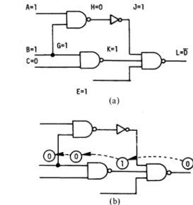
de- termined. Asanexample, forathree-inputANDgate inFig. 1(a) and the fault E s-a-0,weassignthe valueDtothe output E and l'stoallinputsof theANDgate since these valuesare uniquely implied bythe fault E s-a-0. However, for the fault E s-a-1,weassign onlythe valueDtothe output E. All the inputvalues of the AND gate areleftunspecified, i.e.,X, since those values arenotdetermined uniquelyfrom Es-a-I [see Fig.1(c)].
As anexample,consider the circuit ofFig.2.Forthefault Ls-a-1,weassignthe valueD tothe lineLand I'stotheinputs J, K, and E. Then after theimplication operation,wehavea testpattern for the fault withoutbacktracks, asshown in
Fig.
B=l E=D
(a)
A=X
C -X E=D
(c)
A=lB=1 E=D
C=D
(b)
A=1 - B=lC=1 E=D
(d)
Fig. 1. Assignment of fault signals. (a) Es-a-0.(b) Cs-a-0.(c) E s-a-1. (d)Es-a-1.
A=1 H=O J=1
E=1 (a)
Fig.2. Effect of fault signal assignment. (a) Fault signal assignment and implication.(b)PODEM.
2(a).Onthe otherhand,inPODEM, the initial objective (L, 0)isdeterminedtosetup thefaulty signalDtothe line L, and thenthe backtraceprocedurestarts. As shown in Fig. 2(b), the backtraceprocedurecausesapath to be traced from the initial objectivelineLbackwardstoaprimary input B. The assign- ment B = 0 implies that L = 1. This contradicts the initial objective,andsettingLtoD fails and a backtrack occurs. As seeninthisexample,theassignmentof Fig. 2(a) is a condition necessary for a testofthefaultLs-a- 1. By assigning the values which areuniquelydetermined,we canavoid the unnecessary choice.
Consider the circuit of Fig.3(a).Suppose that the D-frontier is
IG2j.
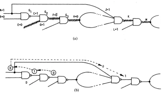
When theD-frontier consists of a single gate, we often havespecific paths suchthat every path from the site of the D-frontier to a primary output always goes through those paths. Inthisexample, every path from the gate G2 to a pri- maryoutput passes through the paths F-H and K-M. In order topropagate the value D or D to a primary output, we have to propagate the fault signal along both F-H and K-M. There- fore,if there exists a test in this point, paths F-Hand K-M should be sensitized. Then we have the assignment C = 1, G= 1, J = 1, and L = 1 to sensitize them. Thispartial sensiti- zationwhich isuniquelydeterminediscalledaunique sensi- tization. InFig.3(a),after the implicationofthisassignment, wehaveA = 1,B= 0, F=
D,
and H=Dwithout backtracks. On the otherhand,PODEMsetstheinitialobjective (F, 0)to propagate the fault signal to the line F and performs the138
(a)
(b)
Fig.3. Effect ofunique sensitization. (a) Unique sensitization and implication.(b)PODEM.
backtraceprocedure.Ifthebacktraceperforms along the path
asshown inFig. 7(b),wehavetoassign 0toA, andwehave J=0 andK= 1by the implication. Althoughnoinconsistency
appearsat thispoint, an inconsistencyorthedisappearance of the D-frontier willoccurin thefuture when thefaulty signal propagates fromHtoK. To findsuchan inconsistency, the PODEM algorithm uses a lookahead technique called the X-path check, i.e., it checks whether thereisanypath froma gateintheD-frontiertoaprimaryoutputsuch thatall the lines alongthepath areatX.However,in ourexample, the back- tracking fromA =0toA = 1 isunavoidable in PODEM.
* When the D-frontier consists ofa single gate, apply a uniquesensitization.
Asseenintheaboveexamples, inordertoreducethenum-
ber ofbacktracks, it isveryeffectivetofindas manyvaluesas
possiblewhich are uniquely determined in each step ofthe algorithm. This is because the assignment of the uniquely determined values could decrease the number of possiblese-
lection.
The executionofthetechniques mentioned abovemayresult
inspecifying theoutputofagateG, but leaving the inputs of Gunspecified. Thistypeofoutputline is calledanunjustified line. It isnecessarytospecify input valuesso astoproducethe specifiedoutputvalues. InPODEM, since all thevaluesare firstassigned onlytotheprimary inputs and only the forward implication is performed, unjustified lines never appear. However,ifwetake thetechniquesmentionedabove,theun- justifiedlinesmayappear,andthus in thiscase,someinitial
objectives will be produced simultaneously so as tojustify them. This will bemanaged by introducingamultipleback- traceprocedurewhich isanextention of the backtraceproce-
dure of Goel [8].
Early detectionofaninconsistencyisveryeffectivetode-
creasethenumber of backtracks. We shall continuetoconsider
sometechniquestofindaninconsistencyatanearlystage.
Whenasignalline L isreachablefromsomefan-outpoint, thatis,thereexistsapathfromsomefan-outpointtoL,wesay that L is bound. Asignallinewhich isnotboundis saidtobe
free. When a
free
line L is adjacent to some bound line, we say thatL is ahead line. As an example, consider the circuit of Fig. 4(a).Inthe circuit, A, B,C,E, F, G, H, and J areallfree lines, and K, L,andM arebound lines.Amongthefreelines, J and Hareheadlinesofthe
circuit since JandH areadjacent
to thebound
linesLand M, respectively.The backtraceprocedureinPODEMtraces asingle path backwardsto aprimary input. However, itsufficestostop the backtraceat,a head linefor the followingreasons. The sub- circuit
composed
of only freelines and thecorresponding
gates isafan-out-free circuit sinceit containsnofan-outpoint.
For fan-out-free circuits, line justification can be performed withoutbacktracks. Hence, we canfindthe values onthepri- mary inputs whichjustify
all the values on the head lines withoutbacktracks. It issufficient,orevenefficient,tolet the linejustification for head lines wait to the last stage of test generation.Stopthe backtraceat ahead line, andpostpone the line
justification
for the head linetothe last.Toillustrate this, consider the circuit shown in Fig. 4(a). Suppose that we want to setJ = 0 and
do
not know at the currentstagethatthereexistsno testunderthecondition J = 0. In PODEM, the initialobjective
is set to (J,0),
and the backtracemay result in theassignmentA = 1.Sincethe value ofJisstillnotdetermined, PODEM againstarts the backtrace procedure,and we gettheassignmentB = 0.A = 1 and B = 0implythat J = 0. Here, by hypothesis, thereexists notest underJ=0, andthusaninconsistencyoccursfQr
thecurrent assignment, andPODIVM
must backtracktochange
theas- signmentonB,asshown in Fig.4(b).
In thiscase, ifwestop the backtracetotheheadlineJ.
we candecreasethe number ofbacktracks,
asshown inFig. 4(c).Performinga unique sensitization,weneedtoidentify paths whichwouldbeuniquely
sensitized.
Also,weneedtoidentify all theheadlines inthe circuit. Thesemustbeidentified,
and thattopological
informationshouldbestoredinsomemanner before the test generation starts. According to our experi- mental results,thecomputing time of the preprocesscan beIEEE TRANSACTIONS ON COMPUTERS, VOL. C-32, NO. 12, DECEMBER 1983
A
(a)
(b) (c)
Fig.4. Effectof head lines. (a) Illustrative circuit. (b) PODEM. (c)
Backtrackingatheadlines.
assmall asnegligible comparedtothe total computing time fortestgeneration.
*
Multiple
backtrace,thatis,concurrenttracing more than onepath, is more efficient than thebacktracealong a single path.Considerthecircuit ofFig. 5. Fortheobjectiveofsetting C = 0, PODEM repeats the backtrace three times along the samepathC-B-A, andalso
along
the same path C-F-Ebefore thevalue 0 isspecifiedon Cbytheimplication. Thus,we can seethat the backtracealonga single path isinefficient and wastestime, whichmay beavoided. From thispointof view, wecouldguessthat the multiple backtrace along plural paths is more efficient than the single backtrace. The modes of procedure which implement multiple backtrace are various. In thefollowing,weshall introduce a procedure formultiple backtrace.InthebacktraceofPODEM,anobjective isdefined by an
objective
logic level0 or 1 andanobjectiveline which is the line at which theobjective logiclevel isdesired.Anobjectivewhich willbe used in the multiple backtrace isdefinedby a triple:(s, no(s), ni(s))
where s is anobjectiveline,no(s) is thenumberof times the
objective
logiclevel 0 isrequiredats, and n,(s)is the numberof
times theobjective logiclevel 1 isrequiredats.Thecomputation of no(s)andn1(s) willbe described later. Themultiplebacktrace starts with more than one initial ob- jective,thatis,asetofinitialobjectives. Beginningwith the setofinitial objectives,asetofobjectiveswhich appear in the midstoftheprocedureiscalled a setofcurrent objectives. A setofobjectiveswhichwillbeobtained at head lines is called a set
ofhead
objectives. Aset ofobjectivesonfan-outpoints iscalleda setoffan-out-point
objectives.Aninitial
objective
requiredtoset 0 toaline s is-~~~~~~~~~~~
Fig. 5. Backtrace.
and an initialobjectiverequired to set 1 to s is
(s, no(s), n1(s))
=(s, 0, 1).
Working breadth-first fromthese initial objectives back- wards to head lines,we determine next
objectives
from the currentobjectivessuccessively
asfollows.1) AND gate [seeFig. 6(a)].
Let Xbe aninput whichistheeasiesttocontrol
setting
0. Thenno(X)
=no(Y), n1(X)
=n(Y)
andfor otherinputsXi,
no(Xi)
= 0,ni(Xi)
=nI(Y)
whereYis the output of theANDgate. 2) ORgate [see Fig.6(b)].
Let X be an input which is the easiesttocontrol
setting
1. Thenno(X) =
no(Y),, n1(X)
=n1(Y)
andfor otherinputsXi,
no(X1)
=no(Y),nI(X
) = 0. 3) NANDgate.Let X
be
aninputwhich is theeasiesttocontrolsetting
0. Thenno(X) = n (Y),
n1
(X) =no(Y)
andfor otherinputsXi,
no(Xi)
= 0,n1(Xi)
=no(Y).
4) NORgate.LetXbeaninputwhichis theeasiest tocontrol
setting
1. Thenno(X) =
n1
(Y),n1
(X) = no(Y) and for otherinputsXi,
no(X,)
=n1(Y),n1(XI)
=0. 5) NOTgate [see Fig.6(c)].
no(X) =
n1(Y),
n1(X) = no(Y). 6) Fan-outpoint[see Fig.6(d)].
1140
(s, no(s),
n I(s))
=(s, 1, 0)
Easiest to control 0 Easiest to control 1
y
X
(a) (b)
x-
x y x ,, X2
(c) (d) Xk
Fig. 6. Gates and fan-out point. (a) AND. (b) OR. (C) NOT. (d) Fan-out
point.
k k
no(X) = j
no(Xi),
n (X) = n 1(Xi).
i=l i=l
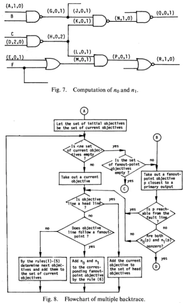
Fig. 7 shows an example to illustrate the computation of no(s) and
nI(s).
Theinitial objectives are(Q,O,1)
and (R,1,O), i.e.,Qand R arefirst required to set 1 and 0, respectively. At thefan-out pointH,nI
(H) is obtained by summingnI
(K)and n1(L), and thecorresponding fan-out point objective becomes(H,0,2).
The flowchart ofFig. 8 describes the multiple backtrace procedure. Each objective arriving at a fan-out point stops its backtracing whilethere exist other currentobjectives. After thesetof current objectives becomes empty, a fan-outpoint objective closestto aprimaryoutput istaken out, if one exists. If the fan-out point objective satisfies thefollowingcondition, the objective becomes the final objective in the backtrace process,and theprocedureendsatthe exit (D) in Fig. 8. The conditionisthatthefan-out pointp is notreachablefromthe faultlineandbothno(p)and nI(p)arenonzero. In this case, weassignavalue
[0
ifno(P) >n1
(p)or1 ifno(p) <n1 (p)]
to thefan-out point andperformtheimplications. The first part of the condition is necessary to guarantee that the value as- signedisbinary, thatis,neither D nor D.In
PODEM,
theassignment
ofabinary
valueis allowedonly
tothe primary inputs. In our algorithm, FAN, we allow to assign a value to fan-outpointsaswell asheadlines, andhence the backtrackingcould occur only atfan-outpointsandhead lines,and
not atprimary inputs.
Thereasonwhy
weassigna value to a fan-outpoint
p is that there might exist a great possibilityof
an inconsistency when the objective in back- tracinghasaninconsistentrequirement
such that bothno(p)
andn1
(p)arenonzero.Soas toavoid thefruitless computation, we assign a binary value tothefan-out point assoon as the objectiveinvolvesacontradictory requirement.
This leadsto theearly detection ofinconsistencywhichwoulddecrease thenumber
of backtracks.Inthemultiple backtrace,ifanobjectiveatafan-outpoint p has a contradictory
requirement,
that is , bothno(p)
and nI(p)arenonzero, stop thebacktraceso astoassign
abinary value to thefan-out point.Whenan
objective
at afan-outpoint
p hasnocontradiction,
thatis, eitherno(p)
or nI(p)
is zero, the backtrace would be continued fromthe fan-outpoint.If all theobjectivesarriveFig. 7. Computation ofnoand n X.
no Does objective
yes
By the rules(l)-(5) Addn0 andnI Addthecur determinenextobjec- O objectivet
tives and add them to to t e corres- objset of the set ofcurrent pond fanout- thobjectives objectives -J pointbythe ruleobjective(6)
Fig.8. Flowchart of multiple backtrace.
atheadlines,thatis, bothsets of currentobjectivesandfan-out pointobjectives areempty, thenthe multiple backtracepro- cedureterminates at theexit(C) in Fig.8.After this, taking out aheadline onebyone fromthesetof head objectives,we assignthecorrespondingvaluetothehead lineandperform theimplication.Fordetails,seethe flowchartof the FAN al- gorithminFig. 9.
III. DESCRIPTION OF THE FAN ALGORITHM The FAN (fan-out-oriented) testgeneration algorithm is similar toPODEM basedontheimplicitenumeration process. However, the FAN algorithm is characterized by putting emphasisonthefollowing points.
1) FAN pays special attention to fan-out points in cir- cuits.
2) FAN is a branch-and-bound algorithm whichadopts manytechniques
presented
inthepreceding
sectionsoas to detect aninconsistencyasearlyaspossible.As mentioned in the preceding section, those techniques would be veryusefulto decreasethenumber ofbacktracks,and thus FAN could befasterandmoreefficientthanPODEM.
IEEE TRANSACTIONS ON COMPUTERS, VOL. C-32, NO. 12, DECEMBER 1983
Fig.9. Flowchart of FANalgorithm.
The flowchart of theFANalgorithmisgiven in Fig. 9. Each boxintheflowchartwill beexplained inthefollowing.
1) AssignmentofFault Signal: In box 1,afault signal D
orDisassignedin themannershown inFig. 1.
2) Backtrace Flag: Themultiplebacktraceprocedureof Fig. 8 has twoentries: one entry is (A) where the multiple backtracestartsfromasetof initialobjectives,andtheother entry is (B) where themultiple backtracestartswitha fan- out-point objective to continue the last multiple backtrace which terminatedatafan-outpoint. The backtrace flag is used todistinguish the abovetwomodes.
3) Implication: We determine as many signal values as possiblewhichcanbeuniquely implied. Todothis,wetake the implication operation which completely traces such signal determinationbothforwardsandbackwardsthroughthecir-
cuit.InPODEM, since allthevaluesareassigned onlytothe primary inputs and only the forward implication is performed, unjustified linesneverappear.However, in FAN, since both forward andbackward implications are performed, the un- justified linesmightappear.Therefore,soastojustify those lines,themultiplebacktraceisnecessary,notonlytopropagate thefault signal (D orD), but alsotojustify the unjustified lines.
4) Continuation CheckforMultiple Backtrace: Inbox4,
we check whether or not it is meaningful to continue the backtrace.We consider that it isnotmeaningfultocontinue thebacktraceifthe lastobjectivewastopropagate DorDand the D-frontier haschangedorifthe last objectivewastojustify unjustifiedlinesand all the unjustified lines have been justified. When it isnotmeaningful tocontinue, thebacktrace flag is
set so as to startthe multiple backtracewith newinitialob- jectives.
5)
Checking D-Frontier: PODEM uses a lookahead tech- nique called an X-path check, i.e., it checks whether there is any path from a gate in the D-frontier to a primary output such that all lines along the path are at X. In FAN, the same tech- nique is adopted to eliminate a meaninglessD-frontier.FAN counts only those gates intheD-frontier which have an X- path.6) Unique Sensitization: The unique sensitization is per- formedinthe manner mentioned
ip
theprevioussection (see Fig. 3). Although the unique sensitization might leave some linesunjustified', those lines will bejustified by the multiple backtrace.7) Determination of a Final Objective: The detailed flowchart of box6is describedinFig. 10. By using the multiple backtrace procedure, we determine a final objective, that is, we choose a value and a line such that the chosen value as- signed to the chosen line has a good likelihood of helping towardsmeeting the initial objectives.
8) Backtracking: Thedecision tree is identical tothatof PODEM, that is, an ordered list of nodes, with each- node
identifying
a currentassignment ofeither0 or 1 to onehead line or onefan-out point,and theordering reflects the relative sequenceinwhich the current assignmentsweremade.Anodeis flagged
iftheinitialassignment
hasbeenrejected
andthealternative
i$
beingtried. Whenbothassignment choicesat a node arerejected,then theassociatednode isremovedand the predecessor node's current assignment is also rejected. The backtracking done by PODEM does notrequiresaving and restoringof statusbecause,ateach point,thestatuscould be revived only by forward implications of allprimary inputs.The samebacktracking
canbedonein FAN, which doesnot re- quiresavingandrestoring ofstatus,by implications ofall as- sociated head lines and fan-out points. However,toavoid the unnecessaryrepetition ofimplications,FANallows theprocess ofsaving and restoring ofstatus to some extent.9) LineJustification ofFreeLines. We can find valueson theprimaryinputs whichjustifyall thevaluesonthe head lines without backtracks. Thiscan
be
done byanoperation identical totheconsistency operation of theD-algorithm.IV. EXPERIMENTAL RESULTS
Wehave
implemented
threeprograms, SPS(single path
sensitization), PODEM, and
FANtestgeneration algorithms,
inFortran onan NEAC System ACOS-1000. TheSPSis a testgenerationalgorithmwhich
isrestrictedtosensitize only
single paths,
and thus it issimpler
thantheD-algorithm,
These programs wereappliedto anumber ofcombinationalcircuits shown in Table 1.Thenumber ofgatesinthesecircuitsrange4
from718 to2982.The resultsareshown inTables IIandIII. Toobtainthedataof TablesIIand III,three programswere executedtogenerateatestforeachstuck
fault.Thenumber of timesabacktrackoccursduring thegener- ation of
each
testpattern wascalculatedby the
programs,and theaveragenumber of backtracksisshowninTableII.Since
PODEM and FAN arecompletealgorithms,
givenenough
time,both will generatetestsforeach
testablefault. However,1142
MULTIPLEBtETRACTE MULTIPLE BACKTRACE tEADOBJECTIVE FREMAFAO-INT FROMTHE SETOF LO8JECTIVE OBJECTIVE INITIAL OBJECTIVES
.CONTRADICTORY
>,N!O R EQOIREMENTAT A
C OIIVOT-POINTOtURRRE
D~~~~~~~~~~~YES
... MULTIPLE BACKTRACE OFFIG. 8 LET THE FANOUT-POINT OBJECTIVE BE FINAL OBJECTIVE TOASSIGN AVALUE
Fig. 10. Determinationoffinalobjective. TABLE I
CHARACTERISTICOF CIRCUITS
Number of Numberof Number of NSmberof Number of Number of
Circuit Gates Lines Inputs Outputs Fanout- Faults
Points
#1 Error 718 1925 33 25 381 1871
Correcting Circuit
#2 Arithmetic 1003 2782 233 140 454 2748
Logic Unit
#3 ALU 1456 3572 50 22 579 3428
#4 ALU and 2002 5429 178 123 806 5350
Selector
#5 ALU 2982 7618 207 108 1300 7550
being limited incomputingtime, wegave upcontinuingtest generation for the faults for which the number of backtracks exceeds 1000.Such faultsarecalledabortedfaults in Table
III.The resultsshown inTablesIIandIIIdemonstrate that, althoughPODEMis faster thanSPS, FAN ismoreeffcient
and faster than both PODEMand SPS.Theaveragenumber
of backtracks in FAN is extremely small compared to PODEMand SPS.
We have also implemented an automatic test generation systemcomposedofFANand theconcurrentfault simulator [9]in suchawaythat thefault simulator is used aftereachtest patternisgeneratedtofindwhat other faultsaredetectedby thetests.Notethat thetest patterniscompleted byreplacing theunspecified inputs by 0's and l's. These faultsaredeleted fromthe fault list. The results of thissystemareshown in Table
TABLE II
NORMALIZEDCOMPUTINGTIMEAND AVERAGENUMBEROF BACKTRACKS
Normalized Computing Time Average Number of Backtracks Circuit
SPS PODEM FAN SPS PODEM FAN
# 1 5.2 1.3 1 31.2 4.9 1.2
# 2 4.5 3.6 1 51.7 42.3 15.2
#3 14.5 5.6 1 189.7 61,9 0.6
# 4 3.1 1.9 1 1.5 5.0 0.2
# 5 3.4 4.8 1 38.1 53.0 23.2
TABLE III TESTCOVERAGE
% Tested Faults X Aborted Faults Z Untestable Faults Circuit
SPS PODEM FAN SPS PODEM FAN SPS PODEM FAN
# 1 99.04 99.20 99.52 0.48 0.48 0.11 - 0.32 0.37
# 2 91.15 94.25 95.49 4.70 3.49 1.38 - 2.26 3.13
# 3 66.25 92.53 96.00 16.25 5.05 0 - 2.42 4.00
# 4 98.77 98.75 98.90 0.07 0.26 0 - 0.99 1.10
# 5 94.73 94.38 96.81 3.54 4.79 2.17 - 0.82 1.02
TABLE IV
FAN COMBINEDWITHCONCURRENT SIMULATOR
Computing Time (seconds)
Circuit % Tested % Aborted # of Test
FAN Concurrent Total Faults Faults Patterns
Simulator
1 3.8 4.6 8,4 99.52 0.11 151
2 34.6 3.7 38.3 95.74 1.13 159
3 7.4 9.5 16.9 96.00 0 215
4 4.0 10.5 14.5 98.90 0 195
5 76.5 18.9 95.4 98.20 0.78 283
IV. Computing times on an ACOS- 1000 (15 millions of in- structions persecond)werereasonable, and a high-speed test generationsystem has beenimplemented,as seen from Table IV.
V. CONCLUSIONS
ThePODEM reported by Goel succeeded in improving the poorperformance of the D-algorithmfor error-correction and translation-typecircuits. However, we have shown that there still remain many possibilities of reducing the number of backtracks inthealgorithm. The FAN algorithm presented in this paperadoptsmanytechniques to reduce the number of backtracks. Experimentalresults onlargecombinational cir- cuits of upto3000 gates show that the FAN algorithm is faster and moreefficientthan the PODEM algorithm in computing time,the numberof backtracks,and test coverage. An auto- matic testgenerationsystemcompsoed of the FAN test gen- eratorand the concurrent faultsimulator has also been im- plemented. The results onlarge circuitsshowthat computing
IEEE TRANSACTIONS ON COMPUTERS, VOL. c-32, NO. 12, DECEMBER 1983
time on an ACOS-1000 were reasonable, and the system achieved ahigh-speedtestgeneration. Recently,anewmethod has beenpresented by Savir and Roth [11] which leadstothe elimination of fault simulation. Considering thatanontrivial amountof time isspentonthe fault simulation,their method could be incorporated in FANtoyielda morepowerfultest generator.
ACKNOWLEDGMENT
Wewould liketo express ourthankstoProf.H.Ozaki and Prof.K. Kinoshita fortheirsupportandencouragementof this work.
REFERENCES
[I] H. Fujiwara and S. Toida,"Thecomplexityof faultdetection:An ap- proachtodesign for testability,"in Proc. 12thInt.Symp.FaultTolerant Comput., June1982, pp. 101-108.
[2] E. B. Eichelberger and T. W. Williams, "A logic design structure for LSItesting,"in Proc. 14thDesignAutomation Conf.,June1977, pp. 462-468.
[3] S.Funatsu,N.Wakatsuki,and T.Arima,"Testgenerationsystems in Japan," in Proc. 12th Design Automation Conf., June 1975, pp.
114-122.
[4] F. F. Sellers, M.Y.Hsiao, andL.W. Bearnson, "Analyzing errors with the Booleandifference,"IEEE Trans.Comput.,vol. C-17,pp.676-683, July 1968.
[5] J. P. Roth, "Diagnosis ofautomatafailures:A calculus and a method," IBMJ. Res.Develop., vol. 10, pp. 278-291, July 1966.
[6] C. W.Cha, W. E. Donath, and F. Ozguner, "9-V algorithm for test pattern generation of combinational digital circuits," IEEE Trans. Comput., vol.C-27, pp.193-200,Mar. 1978.
[7] K, Kinoshita, Y. Takamatsu,and M. Shibata, "Test generation for combinational circuitsby structuredescriptionfunctions," in Proc. 10th Int.Symp.Fault TolerantComput.,Oct.1980, pp.152-154. [8] P. Goel, "An implicit enumeration algorithm to generate tests for
combinational logic circuits,"IEEETrans. Comput., vol. C-30, pp. 215-222, Mar. 1981.
[9] E. G. Ulrich and T.Baker,"Theconcurrentsimulation ofnearly iden- ticaldigital networks," inProc. 10thDesign AutomationWorkshop, June 1973,pp. 145-150.
[10] L. H. Goldstein, "Controllability/observability analysis of digital cir- cuits,"IEEETrans. CircuitsSyst., vol. CAS-26,pp. 685-693,Sept.
1979.
[II] J.Savir and J. P. Roth, "Testing for, anddistinguishingbetween fail- ures," in Proc. 12th Int.Symp.FaultTolerant Comput.,June 1982, pp. 165-172.
N Hideo Fujiwara (S'70-M'74-SM'83) was born in :
_ Nara, Japan, on February 9, 1946. He received X the B.S., M.S., and Ph.D. degrees in electronic en- gineering from Osaka University, Osaka, Japan, in1969, 1971,and 1974,respectively.
Since 1974 he has been with theDepartmentof Electronic Engineering, Faculty of Engineering, Osaka University. In 1981 hewasaVisitingRe- search Assistant Professor at the University of Waterloo, Waterloo, Ont., Canada. His research interests include switching theory, design for testability,testgeneration, faultdiagnosis,and fault-tolerantsystems.
Dr. Fujiwara isamember of the Institute of Electronics and Communi- cation Engineers of Japan and the Information Processing Society of Japan. Hewas amemberoftheTechnicalProgram Committee of the 1982 Inter- national Symposiumon Fault TolerantComputing, and received theIECE YoungEngineer Award in1977.
Takeshi Shimono (S'81) was born on November 25, 1958. Hereceived the B.S. and M.S. degreesin electronic engineering from Osaka University, Osaka, Japan, in 1981and 1983,respectively.
He isnow with the NEC Corporation, Tokyo, Japan. His research interests include design for testability,testgeneration,and fault simulation.
Mr. Shimono is a member of the Institute of Electronics and Communication Engineers of Japan.
1144