Multi Bunch Beam Generation using a Mode Separated Photocathode RF Gun
Abhay P. Deshpande
The Graduate University for Advanced Studies (Sokendai) School of High Energy Accelerator Science
2010
Acknowledgments
Any work that one performs needs a lot of support from many people in and around the individual. I am glad that I received great support from my family, friends and colleagues whenever I planned to do some thing. However, how many times does one get to appreciate and thank these supporters? Fortunately, I get this space for myself and I wish to thank many people for their help and encouragement over years. First I wish to thank Prof. Junji Urakawa, my thesis advisor, for his encouragement and vision. He makes it a point not to assign any work or not to push in researchers towards his own ideas. Instead he left me to choose my own area of work and insisted on finding a topic for myself and focused to teach me how to achieve good quality work. I thank you sincerely for the guidance.
I wish to thank Prof. M. Kawai who introduced me to KEK. I also wish to thank Prof. Shin-ichi Kurokawa who guided me from time to time and made my journey from India to KEK smooth and comfortable. At LUCX facility, I found many new friends with whom I shared most of the time in past 3 years. I wish to thank Dr. Masafumi Fukuda. Most of the work done at KEK was with Fukuda-san and I did enjoy working with him. I wish to thank Sakae Araki who taught me not only technical things but also Japanese language and many other things. I also wish to thank Dr. Kazuyuki Sakaue, Dr. H. Shimizu, Dr. Y. Honda, Dr. N. Terunuma, Dr. T. Omori, Dr. Alex Aryshev, Dr. M. Takano, Prof. N. Sasao (Okayama University), Prof. M. Washio (Waseda University), Dr. S. Liu (IHEP, China) and all other members of LUCX collaboration for discussions and guidance at various stages. I wish to acknowledge the active support from Dr. T. Higo in all aspects of structure design and Prof. K. Floetmann (Desy) for guidance for ASTRA code. I wish to thank Takatomi-san and Kudo-san for manufacturing support.
LUCX is a sub-group of ATF at KEK. Most of us share work on ATF and take shifts on ATF especially as support members. I wish to thank Dr. H. Hayano, Dr. Kuroda, Dr. Kubo, Dr. Okugi, Dr. T. Naito, Dr. S. Boogert (UK), Dr. Phillip Bambade (France), Dr. Deepa-Angal Kallinin (UK), Dr. M. Kuriki (Hiroshima University) and other members of ATF from whom I learnt a lot. I also wish to thank support staff at ATF for the kind support.
My life at KEK went very smooth mainly because of good attention of Ms. Kimiyo Ikeda. She sorted out not only official things but also apartment renting and other routine life issues for me. I have pestered her with large number of forms for my daughter who went to a Japanese play school. I admire Ikeda-san for her kindness and I thank her sincerely. I also thank Ms. H. Sasaki, Ms. H. Kusama and Ms. Y. Ono for the kind support. In Tsukuba I found many good friends and I wish to appreciate Hetti, Dushyant, Sho Yano, Mariajose, Maarja, Tanya and Dr. Simin for all the party time and emotional support. Indians at KEK Dr. Kailash Ruwali, Puneet Jain, Puneet Tyagi and Vijay Chouhan helped any time I asked for.
I did many other activities during my stay for Sokendai. I initiated first student magazine “FLAVOR” in English for Sokendai students. For all such activities, I got good support from Sokendai staff at KEK and
Hayama. I wish to thank Ms. Miyai, Ms. Omura and Mr. Y. Aizawa at KEK office for their support. I wish to thank Prof. Hirata and Dr. M. Iwase from Hayama for constant support in all activities I initiated. In India, I work for SAMEER, R&D Lab of Govt. of India. I wish to thank Director SAMEER and my boss R. Krishnan for permitting me to take Ph.D. work at KEK. I wish to thank Shri. S. S. Bhide, my ex-boss, who introduced me to accelerators and patiently taught me basics of electron linac. Even today, he is keen to listen to me and teach me. Thanks to all my colleagues and friends at SAMEER and to Vasim Khan (now at Manchester University) for rigorous discussions.
My astronomy group, Khagol Mandal, has been an integral part of my life for past 20 years. It was a tough decision to be less active at KM and I wish to thank all my friends and well wishers at KM for their support. I wish to thank Dilip Joshi who has been most instrumental in all things that I did or will do. He is the source of inspiration for me, and many of my friends, to think out-of-the-way and to work hard to achieve the goal. “Failure is not a crime, to not to try is!” That’s what he taught me and I am indebted to him for everything. I also wish to thank Varsha Shukla and Sujata Babar for their kindness and support.
It will be capital mistake if I don’t mention my best friend Dr. Tanuja Dixit. I wish to thank you for constant support (and tolerance!) that you showed for past 15 years.
My mother followed all my plans with great interest and always insisted that I should take up new work and challenges. I wish to express my gratitude to my mother, brothers, sister-in-law for their understanding. I express my gratitude and thanks to my mother-in-law and all extended family and special thanks to Bhashu. My sweet niece Aboli grew up so much in 3 years and I missed her all the time.
My wife, Sujata is my biggest supporter, admirer, critic and she checks all aspects of my personality. She took up post-doctoral work at Tsukuba University in parallel to my work and managed my odd working hours, her own research and our daughter; not to mention the social life that we built up here. She has a good understanding of physics and is keen to listen to new ideas and criticize shallow thoughts. There is no way that I can thank you. I promise you to perform much better in future and make you happier.
Most of the work I did is at the cost of the time that would have been for my daughter Chitra. She was 3 months when I left her in India and grew up with out me. She came to Japan and yet stayed almost without me due to odd working hours that I kept. I am very happy to finish my work at KEK and that I will be soon back to India with my kid.
I wish to dedicate my thesis work to my father-in-law Prakash Kardile who passed away last year. I would miss the party he would have thrown to mark return of us all to India.
Thank you every one. Abhay Deshpande [email protected] Sept. 2010, Tsukuba, Japan
Index
Acknowledgements 3
List of figures 8
List of tables 12
Abstract 14
1 Introduction 17
1.1 RF gun at LUCX 18
1.1.2 New RF gun design 18
1.2 What happens if mode separation increases? 19
1.3 Other features 22
1.4 Scope of current work 22
2 The LUCX setup 26
2.1 The LUCX injector and accelerator 27
2.1.1 RF gun 27
2.1.2 Photo cathode at LUCX 28
2.1.3 Laser system 30
2.2 Travelling wave accelerator 31
2.2.1 RF power system 32
2.3 Magnetic devices 34
2.4 Diagnostic and measurement setup 35
2.4.1 Current monitors 35
2.4.2 Beam position monitor (BPM) 36
2.4.3 Beam profile monitor 36
2.5 Beam energy spread measurements 37
2.6 Start up and beam based alignment 38
3 RF structure design 40
3.1 Comparison of old and new structure 41
3.1.1 Comparison of Q value 45
3.1.2 Increased stability due to large mode separation 46
3.2 Fabrication process and issues 47
3.3 Measurement and tuning 50
3.4 Tolerances and deviations 54
3.4.1 Variation due air-to-vacuum difference 55
4 Beam dynamics simulations 57
4.1 ASTRA code 58
4.2 Simulation parameters 58
4.3 Simulation 1: Energy as function of injection phase θ 60 4.4 Simulation 2: Emittance scans for solenoid variation 60
4.5 Simulation 3: Effect of varying spot size 61
4.6 Simulation 4: Emittance as a function of injection phase 62 4.7 Simulation 5: Energy spread as a function of injection phase 63
5 Measurements and results 65
5.1 Installation and conditioning of the gun 66
5.2 Solenoid field scans 67
5.3 Emittance versus phase 70
5.4 Energy spread measurements 71
5.5 Emittance versus laser spot size 72
5.6 Emittance versus charge 73
5.7 Energy measurement for various injection phase 74
5.8 Estimation of thermal emittance 75
5.8.1 The three step model 75
5.8.2 Relation for thermal emittance 76
5.8.3 Comparison for metal and semi-conductor 78
5.8.4 Measurement method 78
5.8.5 Possibility of direct measurement 82
6 Multi bunch beam loading compensation 84
6.1 Standing wave RF gun 85
6.1.1 Loading for standing wave structure 85
6.1.2 The beam loading term 88
6.2 New RF gun: Total charge: 160 nC, No power multiplication 89 6.3 Beam loading for travelling wave constant gradient (TWCG) linac 91 6.3.1 Calculation for E0L for above time regions 92
6.4 LUCX accelerator with 100 bunch at 45 MeV 94
6.5 Experiment No. 1: 100 bunches, 40 MeV 97
6.6 Experiment No. 2: 300 bunches, 5 MeV 99
7 Results 104
7.1 Results 105
Appendix 1 The 3.5 cell RF gun 107
Appendix 2 Future plans 110
A2.1 π/2 mode compact source at 3 GHz in India 111
A2.2 Linac design 112
A2.3 RF photo cathode gun 113
A2.4 Lasers and the collision chamber 114
A2.5 Ultra light radio therapy linac 115
Appendix 3 Modifications of LUCX 118
Bibliography 119
List of figures Chap 1
Fig. 1.1: The standing wave cavity model
Fig. 1.2: Zero mode cathode fields as a function of mode separation. The π mode field is 130 MV/m
Fig. 1.3: Fields inside a standing wave cavity Chap. 2
Fig. 2.1: The LUCX beam line
Fig. 2.2: Operation principle of RF gun
Fig. 2.3: Measured dependence of quantum efficiency on incident photon energy. The blue curve corresponds to the LUCX data. The brown points correspond to the data from Powell from Ref. 9 Fig. 2.4: LUCX laser system
Fig. 2.5: TWCG linac at LUCX
Fig. 2.6: Field pattern generated by ASTRA for TWCG structure
Fig. 2.7: RF pulse compression using RRCS. Input waveform comes from the Klystron and output is delivered to the linac port.
Fig. 2.8: LUCX RF Power distribution
Fig. 2.9: Details of the old LUCX beam line. The beam line was modified in Mar 2010 after the collision chamber.
Fig. 2.10: Beam profile images: (a) on DMQ screen at MS4G. The vertical beam size is 644 μm (rms) (b) at same location on OTR screen the vertical beam size is 425 μm (rms)
Chap. 3
Fig. 3.1: Old RF gun field pattern and the mounted structure on LUCX Fig. 3.2: Mode separation as a function of iris diameter
Fig. 3.3: Field balance as a function of mode separation for LUCX and new gun. Curve 1 is for old gun using Super Fish code and curve 2 is for old gun with circuit simulations. Curve 3 shows Super Fish simulations for new gun while curve 4 shows circuit simulations for new gun.
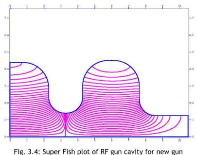
Fig. 3.4: Super Fish plot of RF gun cavity for new gun Fig. 3.5: Axial field plot for π-mode field pattern Fig. 3.6: Field pattern for zero mode fields
Fig 3.7: Field balance as function of half cell radius Fig. 3.8: Assembly drawing of RF Gun cavity Fig. 3.9: Cavity after initial brazing
Fig. 3.10: Cavity after initial brazing (side view)
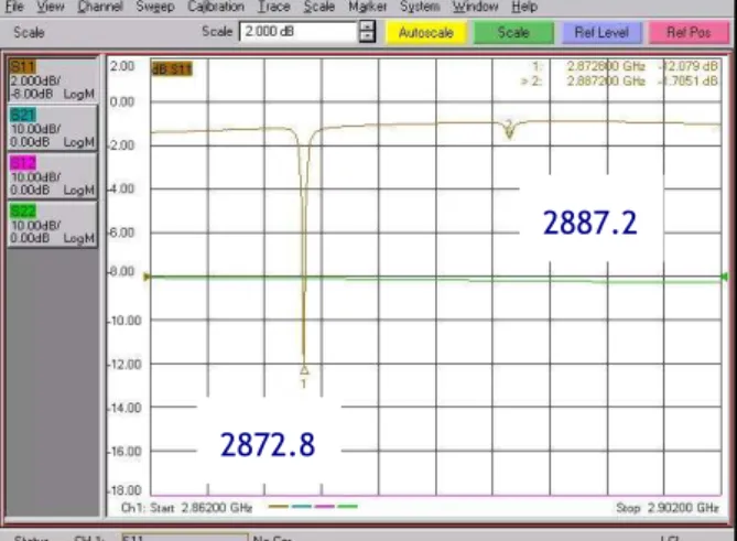
Fig. 3.11: VNA measurement after initial fabrication. The frequencies are very high than the target frequency.
Fig. 3.12: VNA plot before cell to cell brazing. The frequencies are near to desired value and the field balance was almost reached.
Fig. 3.13: Frequency as a function of cut number Fig. 3.14: Waveguide brazed to cells
Fig. 3.15: Final gun with welding operations completed Fig. 3.16: VNA measurement of the final tuning of the gun. Fig. 3.17: Bead pull setup for cavity field measurement
Fig. 3.18: Measured and simulated field distribution along the cavities Chap. 4
Fig. 4.1: Axial field pattern for LUCX solenoid
Fig. 4.2: Axial field strength as a function of current
Fig. 4.3: Energy gain for injection phase for various axial field strengths Fig. 4.4: Emittance versus magnetic field for various axial field strengths Fig. 4.5: Normalized transverse emittance as function of transverse spot radius Fig. 4.6: The dependence energy and emittance on injection phase.
Fig. 4.7: Energy spread as a function of injection phase
Chap. 5
Fig. 5.1: New RF gun mounted on the LUCX beam line Fig. 5.2: Dark current measurements for old and new gun Fig. 5.3: Emittance versus solenoid field
Fig. 5.4: Least measured emittance for the new RF gun. This emittance value is not very stable so we report 1.89 π-mm-mrad (vertical plane) as the stable, low emittance value.
Fig. 5.5: Emittance variations with injection phase
Fig. 5.6: Energy spread (rms) as function of injection phase Fig. 5.7: Emittance for various laser spot sizes.
Fig. 5.8: Emittance variation with bunch charge Fig. 5.9: Energy as a function of injection phase Fig. 5.10: Band structure of Cs2Te
Fig. 5.11: The bunch charge as a function of injection phase.
Fig. 5.12: Plot of square root of axial field as a function of logarithm of quantum efficiency. The fit of this plot determines the parameter B.
Fig. 5.13: Comparison of theory and measurement. The blue curve shows upper limit while the red curve shows the emittance inclusive of the cosine factor in Equation 5.2. The measured data is using method described earlier.
Chap. 6
Fig. 6.1: Standing wave cavity model
Fig. 6.2: New RF gun beam loading compensation
Fig. 6.3: Bunch-by-bunch energy for 300 Bunch with 0.55nC per bunch Fig. 6.4: Power distribution at LUCX
Fig. 6.5: Energy gain curve with power multiplier scheme in the travelling wave linac.
Fig. 6.6: Beam loading compensation in the region of interest for 2 nC per bunch, 100-bunches per train.
Fig. 6.7: Bunch by bunch energy variation for 100 bunches with 2nC per bunch charge
Fig. 6.8: Comparison of compensation scheme for different input power. Fig. 6.9: Proposed power distribution system
Fig. 6.10: Experimental setup for 40 MeV, 100 bunch beam Fig. 6.11: Beam loading for 40 MeV in 100 bunches
Fig. 6.12: Oscilloscope waveforms recorded during the measurement. The red plot is for ICT monitor and it indicates bunch intensity at the location near the screen.
Fig. 6.13: Modified Layout with the linac replaced by a drift tube
Fig. 6.14: Power waveform for low energy experiment. RRCS is turned off. Fig. 6.15: Snap shot of beam position for 5 MeV beam
Fig. 6.16: Curves 1, 2, and 3 plot 100-bunch mode at 40 nC, 230-bunch mode at 80 nC, and 300- bunch mode at 160 nC, respectively.
Fig. 6.17: Oscilloscope data for 300-bunch experiment. The upper two waveforms indicate position of bunches in the BPM while the last curve shows the current transformer waveform. Fig. 6.18: 300 bunch 160nC total charge generation
Appendix 1
Fig. A1.1: The 3.5 cell RF gun profile Fig. A1.2: 3.5 cell gun during measurement Fig. A1.3: Mode spectrum of 3.5 cell RF gun Appendix 2
Fig. A2.1: Proposed lay out of π/2 linac based beam line Fig. A2.2: Linac cavity at various stage of fabrication Fig. A2.3: Super Fish plot of a single cell
Fig. A2.4: SAMEER made side coupled linac tube. The diode gun is on the right end of the figure. RF Window is on top and the in-built target for bremsstrahlung X-rays is on left opposite end and not visible in this photograph. The gun will be replaced by RF photocathode gun.
Fig. A2.5: RF gun cavity profile using Super Fish code Fig. A2.6: SAMEER medical therapy linac
Fig. A2.7: Proposed layout of compact gantry system Appendix 3
Fig. A3.1: The new beam line. The position of bending magnet is shifter further ahead so that the cathode to the dump distance is increased. Two additional bends are introduced. The additional setup for coherent diffraction radiation (CDR) experiment is included after first bend.
List of tables Chap. 2
Table 2.1: Power of laser pulse at various stage Table 2.2: Linac parameters
Chap. 3
Table 3.1: Various parameters for proposed cavity Table 3.2: Comparison of measured Q
Table 3.3: Variation in field balance Table 3.4: Data of measurements
Table 3.5: Comparison of measured results for the old and the new gun. Chap. 5
Table 5.1: Comparison of emittance measurements Table 5.2: Summary of properties of cathodes from Ref. 6 Chap. 6
Table 6.1: RF gun cavity parameter
Table 6.2: Output bunch to bunch parameter Table 6.3: Comparison of beam loading
Table 6.4: Measurement results for multi-bunch beam Appendix 1
Table A1.1: Measured frequencies of various modes for 3.5 cell gun
Appendix 2
Table A2.1: Gun and linac parameters
Table A2.2: Measured linac parameters for existing 15 MeV linac tube Table A2.3: RF gun cavity parameters
Table A2.4: Parameters of X-ray source
Abstract
The Accelerator Test Facility (ATF) at KEK designed the RF gun with Cs2Te photo-cathode for the Laser Undulator Compact X-ray source (LUCX) and ATF linac. The first gun made at KEK was based on Brookhaven National Laboratory (BNL) gun design. Subsequently many improvements were made and an improved gun design was established. Based on the improved gun, eight guns were made by KEK and installed at various institutions in Japan. The expertise thus evolved at KEK for the RF guns from 2002 to 2008. The next request was now to further reduce the beam emittance and make beam energy spread stable over wider range in laser injection phase. It was also essential to increase the charge per bunch and number of bunches per train for increasing the x-ray flux from the LUCX. Around 2005, the Linac Coherent Light Source (LCLS) group at Stanford Linear Accelerator Center (SLAC) suggested that by increasing mode separation, more stability over injection phase variations could be achieved. LCLS group changed their own design to increase the mode separation up to 15 MHz. Following this approach, we decided to increase the mode separation. An advantage in our case is that we also made a new profile for the new gun to achieve high Q (unloaded quality factor) and high shunt impedance.
In this thesis we discuss the evolution of the design of the new gun structure and the procedure which we established to fabricate and process the RF gun. We show the experimental results of measurements and details of the tuning process to achieve the desired frequency at π mode of 2856 MHz with mode separation of 8.6 MHz maintaining the field balance at 1.0. The new gun has higher Q, higher shunt impedance and large mode separation than any gun made at KEK as well as the LCLS gun or the BNL gun. The observed dark currents are also less than earlier gun. Our experience with new large mode separation gun coupled with 130 MV/m fields and Cs2Te cathode is a very essential experience for making Cs2Te a well acceptable material for photo cathode guns.
Beam dynamics simulations were done to estimate the trends of parameter variations. At present, PARMELA, ASTRA, GPT are the three most widely used codes for beam dynamics simulations of the RF guns. We decided to use ASTRA for the beam dynamics simulations of new RF gun mainly because it is much simple to use, free-of-charge and has been bench marked using many new RF gun.
The main focus of beam quality measurement was to compare the parameters for new RF gun with those for the old RF gun, where ever possible. The dependence of emittance was measured as a function of solenoid field, laser injection phase, laser spot size and charge. These measurements played crucial role to fix the optimum operational parameters for the RF gun. We measured the emittance value of 1.89 π-mm-mrad at 1nC charge. Efforts are on-going to check system alignment to push this emittance down to 1.0 π-mm-mrad. Variation in energy spread over the injection phase was also a parameter that we focused upon. The larger mode separation helps to maintain low energy spread over wider phase range. This was observed after careful experimentation.
The thermal emittance issue is discussed in the thesis. We try to estimate the thermal emittance using an indirect method. Direct measurement was not possible due to various limitations of the present setup. We propose to measure the thermal emittance by direct method in near future and we are making changes in our setup accordingly. We conclude that the three step model as it exists today is not sufficient to explain the measured value of thermal emittance for semiconductor photocathode. Hence detailed study will be helpful to understand the complexities of factors involved, which affect the thermal emittance.
Another striking feature of the work done at LUCX is to establish the methods for generation of long multi bunch beam. We succeeded in generating 100-bunches with 0.5 nC per bunch at 40 MeV with peak to peak energy difference less than 0.7%. In other experiment we generate low energy beam of 5 MeV. In this case we succeed to generate 300-bunches with 0.55 nC per bunch with peak to peak energy difference less than 0.85%. These results are very important results for our efforts to make 8000-bunches per train as a first step. We hope to achieve this goal by the end of this year (2010).
At LUCX we are trying to establish the generation of very long pulse trains and we wish to achieve 8000 bunches per train. The future of compact x-ray sources will depend on how long trains with high charge and low energy difference. It will be possible in few years to get very high flux x-ray from such sources. The present thesis is focused on new design of large mode separation gun, fabrication and tuning of the gun. Then tuning this gun to get a low emittance beam and there after generate 300-bunches per train is described.
Chapter 1: Introduction
The Accelerator Test Facility (ATF) group at KEK designed the RF gun system with Cs2Te photo- cathode for the Laser Undulator Compact X-ray source (LUCX) and ATF main linac. The first gun made at KEK was based on Brookhaven National Laboratory (BNL) gun design. Subsequently many improvements were made and an improved gun design was established. Based on the improved gun, eight guns were made by KEK and installed at various institutions in Japan. The expertise thus evolved at KEK for RF guns from 2002 to 2008. The next request was now to further reduce the beam emittance and make beam energy spread stable over wider range in laser injection phase. It was also essential to increase the charge per bunch and number of bunches per train for increasing the x-ray flux from the LUCX. Around 2005, the Linac Coherent Light Source (LCLS) group at Stanford Linear Accelerator Center (SLAC) suggested that by increasing mode separation, more stability over phase variations could be achieved. LCLS changed their own design to increase the mode separation up to 15 MHz. Following this approach, we decided to increase the mode separation up to 9 MHz. An advantage in our case is that we also made a new profile for the new gun to achieve high Q (unloaded quality factor) and high shunt impedance.
Our experience with new large mode separation gun coupled with 130 MV/m fields and Cs2Te cathode is a very essential experience for making Cs2Te a well acceptable material for photo cathode guns. In addition, we also produced 300 bunches per train and established the multi bunch generation. Our plan to achieve 8000 bunches per train will clearly establish the technology and method for future applications.
1.1: RF gun at LUCX
The Accelerator Test Facility (ATF) was proposed at KEK and started operating around 1995 [1]. The original ATF linac had a thermionic gun as the source. With the popularity of RF gun on rise, RF gun activity was started at ATF and an RF gun was successfully installed thus replacing the thermionic gun from ATF linac. At present, we can generate 1 to 20 bunch beam at the ATF RF gun. A similar gun was made at the Laser Undulator Compact X-ray Source (LUCX) facility at KEK [2, 3]. The parameters were tested successfully and the gun was found working well. A 3 meter long travelling wave linac was later on added to generate 45 MeV electron beam with 100 bunches per train [4].
The main reason to construct LUCX was to initiate the study of Inverse Compton Scattering using multi bunch beam. Collaboration was formed and efforts were initiated to make a collision chamber. This chamber is a 2-mirror system to build up the laser peak power and then to collide the laser pulses with the electron beam. Due to this chamber; the peak power of laser becomes high and the flux of x-rays obtained after the collision increases. This novel idea was tested successfully in 2009 [5, 6].
The next stage is to initiate efforts which will help to increase the flux of the x-rays. The LUCX setup was not sufficient to obtain a high flux and so many up gradations were necessary.
1.1.2: New RF gun design:
RF photocathode gun work is on-going at LUCX for long time. The original gun design was based on the Brookhaven National Laboratory (BNL) RF gun [7]. After establishing the technology and operational experience, eight identical RF guns were made and at present are operational at many universities in Japan. Worldwide such efforts were made and the BNL gun was established as a standard model for the RF gun structures.
The BNL gun gives a low emittance beam and stable operation for low repetition rate. But as the demand to further reduce the emittance and increase the charge started increasing, it became essential to check new options and profiles which will help reduce emittance. In 2003, the Linac Coherent Light Source (LCLS) group at Stanford Linear Accelerator Center (SLAC) decided to change the gun profile to make the emittance further low. LCLS changed the gun cavity profile and they chose elliptical cavities with race track layout [8]. LCLS gun also has a dual feed to input RF power from two ports. It is proposed to operate at 120 Hz rep rate. The emittance value will go down due to profile changes. The most important feature for the LCLS gun is the
increased mode separation from 4 MHz to 15 MHz. LCLS suggested to increase the separation between the operational (π) mode and the lower (Zero) mode. They predicted that this will make emittance more stable over large laser injection phase variations. Following their approach, Lawrence Livermore National Laboratory (LLNL) also increased the mode separation of the gun from 4 MHz to 12 MHz [9]. The Swiss Light Source (SLS) also initiated design studies for similar concept [10]. Most recently, Pohang Light Source has proposed similar changes [11, 12]. Following the same approach, it was decided to make a new RF gun at LUCX with increased mode separation. We decided to increase the mode separation from 3 MHz to 9 MHz. We also decided to make high Q and high shunt impedance structure [13]. This will increase the energy of beam coming out of the gun. So we achieve high mode separation, high Q and high shunt impedance. This makes this design very useful for many applications.
1.2: What happens if the mode separation increases?
It has been shown that large mode separation in RF photo cathode gun can enhance the performance of the RF Gun [1]. Mode separation is the difference between π mode frequency and Zero mode frequency. In the standard BNL gun, the mode separation was 4 MHz. At LUCX old gun we achieved a separation of about 3.5 MHz.
To see the effect of increased mode separation we recall the standing wave cavity model and perform some basic analysis. When the RF gun is excited at π mode frequency, the zero mode fields can also get excited. The zero mode fields on cathode can degrade the emittance.
Fig. 1.1: The standing wave cavity model
In the figure, Pi is the incident power; Pr the reflected power, Pe is the emitted power and Pc is the power dissipated in the cavity. Let ωo be the resonant frequency and Q0 the unloaded quality factor. The fields inside the cavity E are related to the power P as:
Pi
Pr
Pe
Pc
P=kE2
where k is a constant of proportionality. We define Ei as the incident field; Er the reflected field and Ee as the emitted field. Using the standard wave cavity model we can state that, the fields in the cavity at time t,
where the filling time tf is given by as and β is the coupling constant Solving the above equation,
We define:
Now for a standard cavity, shunt impedance is defined as:
Q is defined as:
Therefore the energy gain can be,
Thus we can calculate the cathode fields for operation in π mode. Now we define that the zero mode as: f0= fπ -Δf where Δf is the mode separation. We then define the tuning angle as:
i e
F
e E
dt t dE
E (1 )
2 ββ
= + +
) 1 ) ( 1 (
2 ttF
i
e E e
E − −
= +ββ
i F
tt
P Q t
e R
V F
) 1 ( ) 2 ( ) 1
( 0
0 ω +ββ
−
= −
f QL Δf
= 2 ) tan(ψ
0
2 ωL
F
t = Q
e
c
C e
P P
P P
β
β
=
∴ =
2
2 2
2
4 (1 )
(1 )
f
C e
tt i
P kE
P e
β
β β
−
=
= −
+
2 2 0
c
R T V
= P
0 L 1 Q Q
=
β
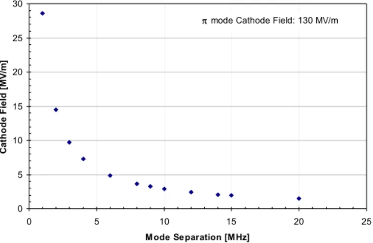
+The magnitude of zero mode fields will vary with the tuning angle ψ. Thus zero mode fields will be much less as compared to π mode for higher Δf [14]. In other words, the magnitude of zero mode cathode fields will be a function of Δf. This is shown in Fig. 1.2.
π mode Cathode Field: 130 MV/m
0 5 10 15 20 25 30
0 5 10 15 20 25
M ode Separation [MHz]
Cathode Field [MV/m]
Fig. 1.2: Zero mode cathode fields as a function of mode separation. The π mode field is 130 MV/m
Thus by increasing the mode separation, the zero mode fields on cathode can be reduced. This will help to reduce the effects of zero mode fields on the beam dynamics. In particular this will be more effective when the klystron pulse length is long. The simulated field pattern for the standing wave fields at π and 0 modes is shown in Fig. 1.3
0 0.2 0.4 0.6 0.8 1 1.2
0 1 2 3 4 5
time [μs]
Normalized Field
Input π Zero
Fig. 1.3: Fields inside a standing wave cavity
By two frequency model simulations, it has been shown that by increasing the separation, the minimum of emittance and energy spread is more stable over injection phase variations [10, 15]. With this motivation we designed the RF Gun at LUCX to achieve higher mode separation. We have designed the cavities to achieve a mode separation of 8.6 MHz as against 3.5 MHz of original cavity.
1.3: Other features
We experimentally found that the increased mode separation gun is more stable over the injection phase variations. The emittance and energy spread varies less with the phase. This was predicted by simulations by other groups. Our experimental results are described in chapter 5. We have achieved a low emittance beam and the energy spread is stable over the injection phase variation. We also changed the profile to achieve higher shunt impedance and higher quality factor. This has helped us to achieve high gradient at the cathode which helps to reduce the emittance.
One of the most important differences between our gun and LCLS gun is that we use Cesium- Telluride (Cs2Te) cathode while the LCLS uses copper as photo cathode. The quantum efficiency (QE) of Cs2Te is much higher than that of copper and so we get a very high charge beam. We have achieved a very low dark current and very high field gradient.
1.4: Scope of current work
The work done in past 2 years at LUCX is focused to design, fabricate and test the new RF gun. Once we achieve a stable value of low emittance, we plan to investigate the parameters that limits in achieving further low emittance at high charge. This will help us to further reduce the emittance value.
Generation of multi bunch beam is other important area on which we are focusing. Our aim is to achieve a long pulse trains with high charge. We propose to achieve a very low peak to peak energy difference in bunch train. At present we have achieved peak to peak difference less than 0.8% and we wish to push it further down. This will be a very good achievement and will boost our research to produce multi pulse x-rays using inverse Compton scattering.
Chapter 2 gives an outline of LUCX setup and the devices that we handle and tune. It also lists our measurement methods and the procedures we invented to make measurements straight forward and easy to initiate. The key of our stable operations lies in the fact that the machine
design is simple and the operation is with least possible troubles. We have done lots of efforts to maintain and up grade the system.
Chapter 3 provides the details of the changes made in the structure design to increase the mode separation. We have opted for curved geometry. One of the main issue was location of brazing joint in the full cell. The design was discussed and fabrication drawings were made. Eventually the RF gun was fabricated in KEK workshop. We faced no serious issues in the brazing joint which is not centered on full cavity. This joint, the tuning and other details are also described in chapter 3.
The beam dynamics simulations of new gun were done using a code ASTRA. Chapter 4 summarizes the beam dynamic simulation result of the new gun structure. After making the gun, it was installed in the existing LUCX facility. Detail measurements were done for the new gun and operation parameters were finalized. Measurement results are summarized in Chapter 5. In the same chapter we describe our procedure for conditioning the gun.
It has been proposed to generate a very long pulse train under the Quantum Beam Project at Japan [16]. In phase 1, using a super conducting linac 160,000 bunches per train will be accelerated. To get a first hand experience of generation and acceleration of long pulse trains, simulations were done to establish multi bunch generation mechanism. In particular, we proposed to generate 8000 bunch per train at 5 MeV and 100 bunches per train at 40 MeV. 40nC in 100 bunches at 40 MeV was successfully accelerated and the results are listed in Chapter 6. The most difficult part was the acceleration of 8000 bunches. The linac offers a high loading so we removed the linac and thus made system of low energy operation. After careful tuning, we succeeded in generating and accelerating 300 bunches per train with total charge of 160 nC. The limit of 300 came from the limitation of the Pockels cell. This result is one of the most striking results of the work done here. This result makes way for longer train acceleration and we have already made plans to accelerate up to 8000 bunches in one train by the end of year 2010.
The work done at LUCX is already opening up new work areas. The experience of multi bunch generation, in particular, is very valuable. This is mainly because the future linacs will demand long bunch-trains, with high charge and high rep rates to push the limits of the compact sources. The flux from such sources at present is just short of second generation sources. With maturity of laser technology and with long bunch-train expertise, the compact machines will reach a higher flux. Thus this field will compete with light sources. The other main aspect of the compact
sources is that such sources are relatively cheaper than the synchrotron sources. Hence, these sources are becoming popular.
When we look from application point of view; the small setups are more favorable in medical, industrial or any university setup. Simple system with good design will help reduce the down time of any accelerator and thus serve the user in a much better way.
References:
[1] F. Hinode et al. ATF Design and Study Report, KEK Report 1995-4
[2] K. Hirano, M Fukuda et al., Nuclear Instruments and Methods in Physics Research, A 560 (2006) 233-239
[3] J. Gao, KEK ATF Internal Report, ATF-04-01, 2004.
[4] Liu S. et al., Nuclear Instruments and Methods in Physics Research, A 584 (2008) 1-8 [5] K. Sakaue et al., Rev. Sci. Inst. 80 (2009) 123304.
[6] K. Sakaue, Ph D Thesis, Waseda University 2009 [7] D. T. Palmer, Ph D Thesis, Stanford University 1998 [8] L. Xiao, D H Dowell et al. SLAC Pub 11213 (2005) [9] S. G. Anderson et al, Proc. of PAC 2007, TUPMS028 [10] J.Y. Raguin, R.J. Bakker, Proceedings of FEL 2005, pp 324
[11] Y. Park, RF gun at PAL-Postech, AAWS-2010 http://kocbeam.kek.jp/ [12] J. H. Hong, I S Koo et al, Proceedings of IPAC 2010 TUPEC014
[13] Abhay Deshpande, J Urakawa et al Nuclear Instruments and Methods in Physics Research, A 600(2009) 361-366
[14] C. Limborg et al. LCLS Tech Note, LCLS-TN-05-3
[15] D. H. Dowell et al. Nuclear Instruments and Methods in Physics Research, A 528, 316-320 (2004)
[16] Quantum Beam Project, http://kocbeam.kek.jp
Chapter 2: The LUCX setup
LUCX is a research collaboration between KEK, Kyoto University and Waseda University. LUCX started as RF Gun Test Bench (RFGTB) when a RF gun was developed for experimental purpose. A 3 meter long travelling linac was then added and the generation of 100 multi bunch beam was achieved. The main focus of LUCX, of course, was to collide laser pulses with electron bunches from multi bunch beam for generation of multi pulse X-rays. This was achieved in 2009. The x-ray flux of LUCX was low, as expected, and hence an improvement effort is on-going. In the modified setup, a new RF gun, separate RF source for the gun and the linac and a four mirror cavity are planned. The ultimate aim of LUCX is to establish technologies to achieve the photon flux of order of 1010 or more photons/sec and thus become a comparable, compact and cheap light source.
In this chapter, we present the features of LUCX and explain the instrumentations that we design, tune and maintain to make precision measurements for various experiments.
The LUCX Logo (designed by K. Sakaue)
2.1: The LUCX Injector and accelerator
The Laser Undulator Compact X-ray Source facility, called LUCX, is the research facility at KEK for Inverse Compton Scattering experiment [1, 2, and 3]. LUCX is a 45 MeV linac test bench to think and try new ideas of acceleration, compensation and x-ray generation as shown in Fig. 2.1. The setup is shown in Fig. 2.9 later on in the chapter.
Fig. 2.1: The LUCX beam line
The LUCX accelerator has a RF photo cathode gun as the source followed by 3 meter long Travelling Wave Constant Gradient (TWCG) accelerator.
2.1.1: RF gun
The old RF gun at LUCX was a BNL Type IV gun with 3.5 MHz mode separation [4]. We changed this gun to new RF Gun with higher mode separation and curved internal surface. The details of new gun are listed in Chapter 3. The new gun is a two cell structure operating at π mode. Like most of accelerators the gun structure also is a cylindrical structure with TM010 as dominant mode. Such structures do have a dipole and quadrupole mode defects and hence the resultant emittance will be higher than similar frequency gun with corrections applied for these modes. To reduce the effect of dipole defects, dual feed configuration can be used. To reduce the effect of quadrupole modes, race track structures are proposed and used [5, 6 and 7]. Use of elliptical cells can reduce the surface fields. We have not, as yet, initiated elliptical and or race track structures to avoid fabrication difficulties. Our focus is to achieve ~ 1 π emittance with our gun design at 1 nC charge.
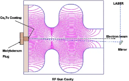
The operational principle of RF photo cathode gun is shown in Fig. 2.2. The incoming laser profile and power is a crucial parameter. We need to choose as high power with a choice of profile to suit our use. Once the laser power is fixed, the quantum efficiency of the photo cathode material will define the electron bunch charge and hence the second important choice to be done is the photo cathode material. The third key issue to decide is the cavity structure. We discuss the laser and photo cathode choice in this chapter while the structure details are listed in Chapter 3. The outgoing electron bunch parameters depend on the laser choice, the photo cathode material choice and the structure design. In addition to above, the surface conditions and the field at the cathode also affect the beam quality. To achieve a low emittance beam it is essential to monitor each of these parameters and hence the RF gun technology needs careful checking at each stage.
Fig. 2.2: Operation principle of RF gun 2.1.2: Photo cathode at LUCX
The photo cathode choice is one of the main decisions to be made when one chooses the RF gun technology. In RF gun the bunch charge depends on the laser power and the choice of photo cathode material. The user can choose a metallic photocathode or a semiconductor photocathode. The LCLS group uses Copper as photocathode material. The main disadvantage in this case is that the efficiency to conversion from photon to electron is very low for copper and hence to generate very high charge bunches, laser power goes high and so the cost of laser system rises. To achieve a high bunch charge, at LUCX we chose semiconductor material Cesium-Telluride (Cs2Te) as the photocathode.
The Cs2Te has comparatively low life time at peak quantum efficiency. The quantum efficiency (QE) of Cs2Te decreases rapidly over time [8]. In our case we found the QE dropped to about 3
0.5% in about a month after the coating. In our earlier gun, the cathode lasted for around 3 yrs with ~ 0.3% QE in high fields of about 130 MV/m despite of long operations. The successful operation with Cs2Te photo cathode in presence of fields over 130 MV/m at LUCX is a significant achievement to boost the user’s confidence of many labs in the world to switch to Cs2Te photocathode.
Our system uses a molybdenum plug inserted in the RF gun via load lock mechanism. As an initial conditioning before the Cs2Te coating, the plug is inserted at the cathode position and subjected to high fields of over 130 MV/m. The plug is cleaned through this conditioning, and at the completion of the process it is transferred to the coating unit in a vacuum chamber. Once the plug is inside the coating chamber, a 10 nm thick coating of Telluride is applied. Then the Cesium deposition is commenced, and the quantum efficiency (QE) is monitored over time. The photo current peaks at some point, and then starts to fall. In our process, the coating is discontinued when a stable QE of nearly 4% is reached. Next, the QE is measured as a function of photon energy. Figure 2.3 shows the LUCX coating data in blue dots and the data from Powell in brown dots [9]. When we use this photo cathode in our gun with our laser system, we easily achieve a charge of around 1 nC per bunch and stable operation with a gradient of 110 MV/m or higher.
Fig. 2.3: Measured dependence of quantum efficiency on incident photon energy. The blue curve corresponds to the LUCX data. The brown points correspond to the data from Powell from Ref. 9
In our setup, we achieve high charge per bunch with our laser system and we achieved stable, long operations and hence the choice of Cs2Te is well justified for us.
2.1.3: Laser system
Along with the gun structure and cathode, choice of laser system is a defining parameter. In RF gun, the laser strikes the photo cathode and an electron bunch is generated. The laser profile defines the bunch profile. The laser power defines the bunch charge. The phase at which laser is injected defines the bunch exit energy. The stability of laser defines the operational stability of the system. Hence, stable laser system with low jitter is needed.
Our laser system is a multi pulse laser system [10]. The seed laser is Time Bandwidth Neodymium Vanadate (Nd: YVO4) mode locked oscillator with a 357 MHz frequency. The average power is 7W at 1064 nm wavelength and pulse duration is 7ps (FWHM). The infrared (IR) pulses produced at 2.8ns (corresponding to 357MHz) pass through a Faraday isolator F1 into a Pockels Cell PC1. The Pockels cell chooses the number of pulses depending on the choice of user. In May 2010, we installed a new fast rise time Pockels cell and now it is possible to choose up to 8000 pulses for operation. The earlier Pockels cell had limitation of minimum 4 to maximum 300 pulses only. The selected pulses pass through double pass amplifier AMP1 and then through Pockels Cell PC2 to enhance the contrast ratio. Then it passes again through an Amplifier AMP2. The high-power pulses are then passed through non linear optics BBO crystals to produce the fourth harmonic. The final outcome is a 266 nm ultraviolet (UV) laser with a pulse length of 12.5 ps (FWHM). Figure 2.4 shows the schematic of laser system.
Table 2.1: Power of laser pulse at various stage
Oscillator output 7 W
Frequency 357 MHz
Power per pulse 19.6 nJ 2 Amplifier Double Pass 39 μJ
IR to UV conversion 3.9 μJ (Incident on photo cathode)
QE 0.3 %
No. of photons incident 5.25 x10¹²
Bunch Charge 2.5 nC (variable)
Fig 2.4: LUCX laser system (image courtesy K. Sakaue) 2.2: Travelling wave accelerator
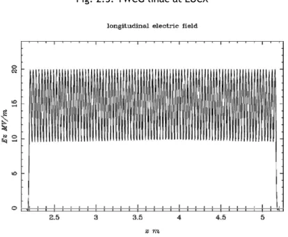
The LUCX main accelerator is a 3 m long Travelling Wave Constant Gradient linac made by Mitsubishi Heavy Industries. The TWCG structure is a disc loaded structure operating at 2π/3 mode. The end cells are matching cells in which power coupling slots are made. The power enters through a coupling slot in matching cell number 1 and exits through coupling slot at matching cell number 2 at exit. The bunch can be launched at any phase by varying the phase through phase shifter. To achieve a low energy spread we launch the bunch off-crest and hence have slightly low energy than we can achieve through this linac. Figure 2.5 shows the TWCG linac at LUCX while Fig. 2.6 shows the field pattern simulated using beam simulation code ASTRA for the linac. The parameters are listed in Table 2.2.
Table 2.2: Linac parameters
Frequency 2856 MHz
Mode of operation 2π/3
Shunt Impedance 60 MΩ/ m
Attenuation 0.57 np
Filling Time 0.830 ms
Peak Field 20 MV/m
Number of accelerating cells 84
Number of Coupler Cells 02
VSWR 1.01
Q 12000
Group velocity 0.0204c- 0.0065c
Fig. 2.5: TWCG linac at LUCX
Fig. 2.6: Field pattern generated by ASTRA for TWCG structure 2.2.1: RF power system
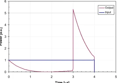
In our setup we use 80MW Toshiba E3712 Klystron as RF source. The klystron has 4 μs pulse width. To achieve high power needed to compensate high charge multi bunch beam, we use a Resonant Ring Power Compressor (RRCS) type pulse compressor scheme [11]. This scheme is like the SLAC Energy Doubler (SLED) [12, 13] scheme with the main difference that SLED is a standing wave type resonator while RRCS uses travelling wave resonator. Using a phase switcher,
the phase of first 3 μs of RF pulse power is switched-off by 180 deg. During this time, the RF power builds up into the resonant ring and is stored in the cavity. At end of 3 μs, the phase is switched back and the stored power from cavity adds up with the power coming from klystron, at the linac port. We usually operate the Klystron at 41.7 MW power. Hence after using the RRCS instead of 4 μs, 41.7 MW RF power, we achieve 1 μs, 135.5 MW peak power at the output of RRCS. The input and output power structure is shown in Fig. 2.7. The multiplication factor in this ideal case is around 5.25 where as we actually achieved a multiplication factor of around 3.25.
0 1 2 3 4 5 6
0 1 2 3 4 5
Time [μs]
Power [a.u.]
Output Input
Fig. 2.7: RF pulse compression using RRCS. Input waveform comes from the Klystron and output is delivered to the linac port.
The power thus obtained from Klystron is further divided and attenuated before it goes to gun or linac. Of the 135.5 MW power, 30% i.e. 40.6 MW goes to linac. Of the remaining 94.8 MW, 50% goes to load and about 47.4 MW goes to RF gun. The existing power scheme is shown in Fig. 2.8.
Fig. 2.8: LUCX RF Power distribution (image courtesy M. Fukuda)
2.3: Magnetic devices
The LUCX aims to focus beams to vertical size of less than 50 μm. To achieve this, high field quadrupole magnets are inserted in the beam line.
As shown in Fig. 2.9 on next page, at the RF gun exit, a solenoid is placed to help the emittance compensation. This solenoid focuses the electron beam to a minimum size, near the focal length, at which the linac should be placed. We have introduced a 4-magnet Chicane after the solenoid. This is needed to make space for a small mirror to incident laser on the photocathode nearly perpendicular to the surface. The chicane bends in horizontal plane and takes the beam off-axis and then brings it back on-axis. This bend, introduces a divergence to the beam, which may not be fully recovered if the chicane is not neatly aligned. Thus the x-y asymmetry is introduced which leads to different emittance values of x and y plane emittance in our case.
The chicane also serves as an energy slit in our case. If the energy spread is more than 1 MeV, some part of the beam is cut off. In multi-bunch case, the chicane ensures that peak energy difference is in acceptable range and this good quality beam is passed on to linac. If the energy difference is too high, chicane blocks some bunches and further tuning is expected to correct for the loss. Thus we ensure that a good quality beam appears at the entrance of the linac.
After the chicane, a quadrupole triplet (QA1G-3G) is inserted. This triplet can be used to ensure that the beam size at the entrance of the linac is small and that the beam has a round shape. After this triplet, the linac is placed to accelerate the beam to high energy. After the linac, two set of doublets are introduced. The first doublet, QD1G and QF1G, focuses the beam at the collision point (CP1G) to obtain 50 μm beam size in the vertical plane. Simulations show that this needs a large compression and hence a large field is needed at the quadrupole. As a consequence, the beam size increases rapidly after the minima at the collision point and the beam size will go on increasing continuously. Hence, the second set of doublet, QD2G and QF2G, is used to re-focus the beam to the dump.
The collision point is the location at which the electron beam collides with the laser. The outgoing electrons and the generated X-rays are in the same direction. Hence, X-ray detection will be impossible, unless we bend the beam. Therefore we use a bending magnet (BA1G) to bend the beam in vertically downward direction to the dump.
Fig. 2.9: Details of the old LUCX beam line. The beam line was modified in Mar 2010 after the collision chamber.
2.4: Diagnostic and measurement setup
The location of monitors, BPM and ICT are shown in Fig. 2.9. Various measurements are done using a combination of some diagnostic devices and magnets. We now list few essential things about some devices and the way they are used. This section follows closely earlier work at LUCX [10].
2.4.1: Current monitors
At LUCX we use Faraday Cup (FC) and Integrating Current Transformers (ICT) to monitor and measure the beam current. Faraday Cup is a destructive type measurement setup. It is essentially a high conducting, low Z metal cylinder with large thickness. Z is the atomic mass number. When the electron hits this metal cup a proportional current is produced. The FC is isolated and hence we get a direct measurement of electron beam charge.
In contrast, ICT is used to measure intensity of short bunches in a non-destructive way. The ICT is a circular hollow disc type structure through which the beam passes through all the time. When a bunch passes through the ICT, induced current flowing through ICT can be detected. The ICT integrates the signal with a time constant and hence losses are suppressed. With sufficient fast rise time ICT available commercially, ICT can be used to measure micro-bunch charge by proper choice of time constant. Thus ICT is very useful in accelerator applications.
2.4.2: Beam position monitor (BPM)
BPM, as the name suggests, is used to monitor the position of the beam to fix the beam orbit. At LUCX we use button type BPM’s having four electrodes. When a bunch passes in between these buttons, an image charge is induced on the diagonally opposite electrodes. The induced charge is seen as a bi-polar signal pulse with the amplitude proportional to beam charge and the distance from the beam. If the beam is passing off-axis, asymmetric charge is induced in a pair of buttons and thus the beam position can be traced proportional to this asymmetry. Thereby we can fix the position of beam in that particular BPM. Plotting the position of beam, in successive BPM’s, gives the entire beam orbit from the gun to the dump.
2.4.3: Beam profile monitor
We use two types of screen monitors to observe the beam. A highly sensitive alumina fluorescent plate (AF995R, Demarquest Co.) is selected for use as the screen material. The screen is made of 0.5% chromium oxide doped with alumina and reaches peak scintillation at a wavelength of 693 nm. A 100-μm thick screen is mounted on an inserting device at 45 deg relative to the beam. The main disadvantage of this type of screen is a slight enlargement of the scintillation indicating a larger beam size than that of the original beam. This disallows the use of the screen for precise beam size measurements. But with its high sensitivity to even pico-ampere charge, the screen is very useful for finding beams and monitoring dark currents. Thus, we use the screen mainly for tuning and use an optical transition radiation (OTR) screen for beam size measurements.
The Optical Transition Radiation (OTR) method is mainly used to image the transverse profile of beam. When the charged particle beam strikes a thin stainless steel plate, OTR radiation are seen both in forward and backward direction. By inserting the metal disc at 45 deg, the backward OTR can be diverted out of the beam plane, through a window onto a CCD camera. By observing these radiations, we can build the beam profile in transverse planes.
In both case, the screen is initially calibrated using a known distance pattern. It could be a marking on the screen or some small screw in the vicinity of the screen. The image of such known device is obtained with a known magnification and there by microns per pixel ratio is decided.
At LUCX we have 04 screens with OTR and DMQ setup. At all four locations, inserting device is common with DMQ and OTR screen mounted one below other. Selecting DMQ brings the screen
1 in front of the beam. Selecting OTR, the screen further moves down and stainless steel plate faces the beam.
Fig. 2.10 shows beam profile obtained at same location using a DMQ and OTR screen. The fit is obtained in each case and it shows the deviation in size obtained from both the methods.
a b
Fig. 2.10: Beam profile images: (a) on DMQ screen at MS4G. The vertical beam size is 644 μm (rms) (b) at same location on OTR screen the vertical beam size is 425 μm (rms)
2.5: Beam energy spread measurements
The beam energy spread measurements are done using screen MS4G OTR. Initially, the beam profile is observed on this screen. The phase of injection for RF Gun is adjusted to minimize the spread. The linac phase is also set so as to obtain minimum energy spread on the screen. The crucial part is to calibrate the screen pixel to the energy spread. This is done by using the analyzer magnet and time delay units. To begin with, the analyzer magnet is set to current so that the beam appears at center of the screen. The beam injection is then delayed in steps. This changes the beam energy and the beam moves on the screen. Average value of beam position and the error is noted. For each case, the current of analyzer magnet is then varied to bring the beam to center position and corresponding energy is recorded. Thus we get screen pixel as a function of beam energy. This calibration is used to measure the energy spread.
Using the same screen MS4G OTR, the magnet and the BPM near the screen it is possible to find out bunch-to-bunch energy difference. This is not directly measured value but estimated using the BPM-magnet-screen combination. As before, energy spread for less number of bunch is measured using screen as discussed above. There after a multi bunch beam with 100 bunches is launched. We know the mean energy from 4 bunch measurement at which the analyzer magnet current is
fixed. The 100 bunches pass through the magnet and through the BPM. Since the energy of bunches is different from the mean energy, they trace a different path through the BPM and the position can be recorded. The difference in position is correlated to difference in energy and thus we can know the bunch-to-bunch energy variation. For 4 bunch mode, we can thus measure energy spread of the bunch while for 100 bunch beam we can not measure individual bunch energy spread but bunch to bunch energy deviation can be found. Thus we measure the peak to peak energy difference for multi bunch beam which is very important parameter. If the beam loading is compensated properly, the peak to peak variation for 100 bunches is less than 1%.
2.6: Start up and beam based alignment
Like any other accelerator, starting up the LUCX and setting base parameters is the most critical part. LUCX is shut down each day and hence on each day at start up we have established a procedure to ensure that the beam quality is nearly same as on the day before. Initial quality assessment and tuning is done to stabilize the machine and there after experiments can be done as per the plan of the day.
After warming up of the system, laser profile is measured as a starting point. The laser intensity is measured each day. The system is then turned on and all the magnets are switched off except the bending magnet. The beam is turned ON and beam current is measured. The first step is to ensure the beam center alignment with the solenoid magnet. This is done using a beam based alignment (BBA). The solenoid current is varied from optimum solenoid current by plus and minus 5 A. At each setting of solenoid, the BPM reading for x and y plane is registered. Then the solenoid current is changed by 5A and the deviation is BPM reading is checked. If the deviation is large, the position of laser incidence on cathode is varied using mirror control. This process is repeated many times till we find that the deviation for BPM in each plane is less than 0.01 mm over 15A current range.
Once the beam is aligned with respect to solenoid axis, phase plot is recorded. The injection phase is varied and corresponding charge is recorded. From this setting, the phase of injection is set for minimum energy spread location. There after the screen after the bending magnet, MS4G is put on and profile of beam is observed on this screen. The linac phase is adjusted so that the energy spread is minimized.
After these initial tuning, the beam is observed at screen after the collision point. The beam size is then measured using the OTR screen at MS3G. Emittance is measured at this location by using
the quadrupole doublet. The solenoid current is then varied in small steps and the emittance measurement is repeated. Eventually, solenoid current versus emittance is plotted to find out the best compensation setting. This is the setting for minimum emittance and most experiments are done with this position as the reference position.
References:
[1] K. Hirano, M Fukuda et al., Nuclear Instruments and Methods in Physics Research, A 560 (2006) 233-239
[2] Liu S. et al., Nuclear Instruments and Methods in Physics Research, A 584 (2008) 1-8 [3] K. Sakaue et al., Rev. Sci. Inst. 80 (2009) 123304.
[4] X. J. Wang et al. Nuclear Instruments and Methods in Physics Research A 375 (1996) 82-86 [5] L. Xiao, D H Dowell et al. SLAC Pub 11213 (2005)
[6] Y. Park, RF gun at PAL-Postech, AAWS-2010 http://kocbeam.kek.jp/ [7] J. H. Hong, I S Koo et al, Proceedings of IPAC 2010 TUPEC014 [8] S. H. Kong et al. J. Appl. Phys., 77(11), (June 1995)
[9] R. A. Powell et al. Phys. Rev. B, Vol. 8, Number 8 (Oct 1973) [10] K. Sakaue, Ph D Thesis, Waseda University 2009
[11] S. Yamaguchi et al. KEK Pre-print 94-87 (1994) [12] Z. D. Farkas, SLAC-TN-73-08 (1973)
[13] P. B. Wilson, SLAC-TN-73-15 (1975)
Chapter 3: RF structure design
The LCLS gun design group has shown that by increasing the separation of mode frequencies, it is possible to have a large range of injection phase variations over which the emittance minimum can be maintained to a low value. Technical report from LCLS has motivated Lawrence Livermore National Laboratory (LLNL) to switch from small mode separation to large mode separation. The LCLS group went from 4 MHz separation to 15 MHZ while the LLNL group went up to 12 MHz separation. Following these two references, we decided to adopt the strategy of increasing the mode separation at LUCX setup. We chose new design to increase the mode separation up to 9 MHz from the existing 3.5 MHz separation. This needed some changes in the cavity profile. It was also decided to alter the profile so as to get high Q structure with higher shunt impedance.
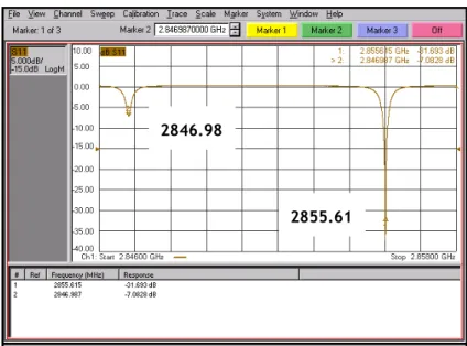
This chapter describes the evolution of the new gun structure and the procedure which we established to fabricate and process the RF gun. More importantly the chapter explains the experimental results of the measurements and details of the tuning process to achieve the desired π mode frequency of 2856 MHz with the mode separation of 8.6 MHz maintaining the field balance at 1.0. Though the current work is focused on comparison between old and new LUCX gun; yet a comparison with the modified gun at ATF, KEK is also considered at some point. The new design has higher Q than the original and the modified gun at KEK.
3.1: Comparison of old and new structure
LCLS gun design review group has shown that by increasing the separation of mode frequencies, it is possible to have a large range of phase variations over which the emittance minimum can be maintained to a low value [1]. Technical report from LCLS has motivated LLNL group to switch from low mode separation to high mode separation. The LCLS group went up to 15 MHZ from 4 MHz separation while the LLNL group went up to 12 MHz separation [2]. Following these two references, we decided to adopt the strategy of increasing the mode separation at LUCX setup. We chose to increase up to 9 MHz from the existing 3.5 MHz separation [3, 4]. This needed some changes in the cavity profile. It was also decided to alter the profile so as to get high Q structure with higher shunt impedance. We selected circular profile for the new structure.
The structure of the original LUCX RF gun (hereinafter, the “old gun”) was close to the BNL type IV gun structure as shown in Fig. 3.1. Our main modification at KEK, after years of experience, was to replace the Helicoflex seal joint with a brazing joint. Another major change was to introduce the new ‘deformation tuners’ in the tuner region [5]. These tuners do not penetrate the gun cavity, but maintain a wall thickness of about 2 mm. A screw-type mechanism is used to move the tuner, and with it the cavity wall, up or down, and thereby change the cavity frequency. Each cell has four diametrically opposed tuners, and the cavity frequency can be changed up to ±1 MHz. The original LUCX RF gun cavity had a mode separation of 3.52 MHz and a field balance (Ehalf / Efull) of 1.30. Our target was to increase the mode separation to 8.6 MHz while maintaining filed balance of 1.0.
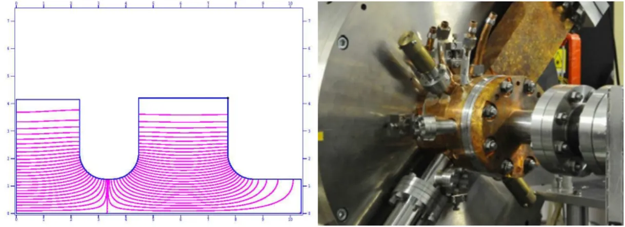
Fig. 3.1: Old RF gun field pattern and the mounted structure on LUCX
The mode separation was increased by increasing the coupling between the cells through two adjustments, namely, increasing the iris diameter and reducing the length of the drift tube