RT-Level Identification of Potentially Testable Initialization Faults
Jaan Raik1 Hideo Fujiwara2 Anna Krivenko1
1
Department of Computer Engineering,
Tallinn University of Technology,
Raja 15, 12618 Tallinn, Estonia
[email protected]
2
Graduate School of Information Science,
Nara Institute of Science and Technology,
Kansai Science City, Nara, Japan
[email protected]
Abstract
In sequential Automated Test Pattern Generation (ATPG) based on a three-valued algebra (0,1,X) a fault is said to be hard-detected if a fault effect (0/1 or 1/0) appears at a primary output. However, not all the faults can be tested by such hard-detection model. Many faults belonging to the class of initialization faults are known to be covered only by resorting to potential detection (effect 0/X or 1/X). Existing high-level fault models assume hard-detection and therefore are not capable of handling the initialization faults. The goal of current paper is to propose high-level identification of such potentially testable initialization faults. Experiments presented in the paper show that potentially detectable initialization faults form a large subset of all the faults not testable by hard-detection. As a result of the proposed approach, both, the speed as well as the confidence level of RTL ATPG can be increased.
Keywords:
Register-transfer level, ATPG, potential fault detection. 1. Introduction
While the problem of test pattern generation for combinational circuits is considered to be solved there still exists no satisfactory solution for sequential ATPG. It is by now commonly accepted that deterministic gate- level algorithms [1, 2] can not cope with the underlying complexity of sequential designs. Several high-level [3- 5] and simulation-based [6-9] methods have been developed but the achieved fault efficiency is still far from 100 per cent.
A common industry practice is therefore to resort to full- or partial-scan design, where scan paths are inserted into circuit flip-flops converting a sequential design into a pseudo-combinational one. Full-scan design is easy to accomplish and it allows application of the combinational ATPG resulting in a near-100-
percent fault efficiency. However, the scan path approach has a number of drawbacks including performance and routing overhead, difficulty to achieve at-speed testing, excessive amount of test data, and last but not least, yield loss because of over-testing.
Taking into account the limitations of the scan approach there is a need for efficient test generation methods targeting sequential circuits. On the other hand, as it was mentioned above, existing sequential ATPG methods do not reach satisfactory fault coverage. Furthermore, the high-level and simulation-based solutions are unable to identify untestable areas of the circuit. Thus, the achieved fault efficiency is usually low and this in turn decreases the test engineer’s confidence in the result. This is one of the main reasons why sequential ATPG has not met a wide acceptance among the industry.
In sequential Automated Test Pattern Generation (ATPG) based on a three-valued algebra (0, 1, X) a fault is said to be hard-detected if a fault effect (0/1 or 1/0) appears at a primary output. However, not all the faults can be tested by such hard-detection model. Many faults belonging to the class of initialization faults are known to be covered only by resorting to potential detection (effect 0/X or 1/X). It is obvious that any ATPG algorithm first attempts to generate hard- detection tests. This means wasting test generation time also for those faults that may only be detected potentially.
In their previous works, the authors of the paper developed a method [10, 11] for untestable fault identification starting from Register-Transfer Level (RTL) ATPG. As a result the fault efficiency was significantly increased but still remained well below 100 per cent. Experimental analysis presented in current paper points out that an important subclass of faults, the potentially detectable initialization faults, form a large subset of all the faults not testable by the hard-detection model. This is particularly true for control-dominated circuits.
9th IEEE Workshop on RTL and High Level Testing (WRTLT'08), pp.57-62, Nov. 2008.
Existing high-level fault models assume hard- detection and therefore are not capable of handling the initialization faults. This means that the high-level algorithms spend test generation time also for those faults that may only be detected potentially. Thus, it would be desirable that the high-level ATPG would have knowledge about the faults that cannot be tested by the hard-detection model.
The goal of current paper is to propose high-level identification of potentially testable initialization faults. As a result of the proposed approach the confidence level of sequential ATPG can be increased. As it will be pointed out in this paper, the proposed potentially testable fault identification is applicable, both, for stuck-at and high-level fault models.
The paper is organized as follows. Section 2 introduces the basic definitions and classification of fault types. Section 3 presents the experimental analysis which shows the ratio of potentially testable initialization faults in sequential designs. This is one of the main motivators for current work. In Section 4, a high-level method for hard-untestable initialization faults is introduced. The Section also discusses the relation of such untestability analysis for gate-level stuck-at faults. Finally, conclusions and future extensions to the method are given.
2. Basic definitions
Sequential ATPG and fault simulation typically relies on the 3-valued logic algebra 0, 1, and X, where X is an artificial logic value to represent the unknown or don’t-care state.
Definition 1: A fault f is said to be hard-testable iff for this fault a fault effect (0/1 or 1/0) can be propagated to a primary output.
Definition 2: A fault f is only potentially testable iff it is not hard-testable and for this fault either 1/X (i.e., the fault-free value is 1 and the faulty value is unknown X) or 0/X can be propagated to a primary output.
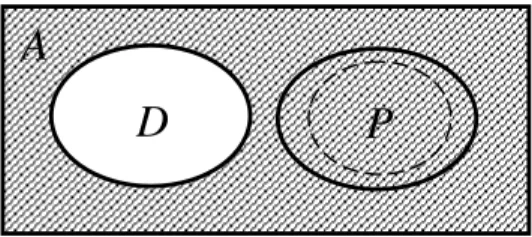
Let us denote the set of all stuck-at faults by A, the set of hard-testable faults by D and the set of potentially testable faults by P. Relations between these three sets is presented in Fig. 1. The goal of the method proposed in current paper is to increase the fault efficiency of high-level fault models by identifying potentially testable faults from RTL. The area of faults identified by current method is depicted by the dashed circle in the Figure.
Figure 1. Relations between fault classes
3. Experimental analysis of fault classes Table 1 presents the experimental analysis of four sequential designs. The benchmarks were chosen from the HLSynth92 and HLSynth95 families and they were synthesized to RT-level from behavioral VHDL descriptions using the high-level synthesis tool SYNT from Synthesia. Subsequently, the RTL descriptions were synthesized to logic-level by Synopsys Design Compiler. The circuits were tested by a combination of two sequential ATPG tools: a simulation-based ATPG SBGEN [12] and a hierarchical ATPG DECIDER [13].
Table 1. Fault distribution in sequential designs
Circuit GCD SOSQ MULT DIFFEQ
Total faults 1760 2130 2242 10326 Hard-detected 1569 1514 1417 9853 potential-
detect. 16 181 117 14
uncontr./unobs. 98 275 505 320 reg. untestable 65 130 130 130
other 12 30 73 9
Fault
efficiency 99.32 98.59 96.74 99.91
In the Table, the rows have the following meaning. Row ‘total faults’ shows the number of stuck-at faults in the circuit. Row ‘hard-detected’ gives the number of faults that were covered according to the hard- detection model. Row ‘potential-detect.’ presents the number of potentially detected faults covered by the sequential ATPG tests. This result was obtained by running a sequential stuck-at fault simulator. Row
‘uncontr./unobs.’ stands for the sum of uncontrollable and unobservable faults. These are faults, which are caused by constant inputs and unconnected gate outputs, respectively. This type of faults is very easy to identify and they are reported by most commercial and academic fault simulators. Row ‘reg. untestable’ stands for a special class of register control faults, which can be proved untestable from the RT-level as shown in [11]. Row ‘other’ includes all the remaining faults.
D
A
P
We can make the following conclusions based on the fault distribution shown in Table 1. First, if we take into account the classes of uncontrollable/ unobservable, register untestable and potentially detected initialization faults then the calculated fault efficiency is high, ranging from 96.7 to nearly 100 per cent. However, since traditional high-level ATPG is not capable of identifying the untestable and the initialization faults the achieved confidence level in terms of fault efficiency is very low. In [11], the authors proposed a method for formally proving untestable faults in registers from the high-level. The goal of current paper is to extend RTL ATPG by potential detection capabilities in order to achieve higher fault efficiency.
4. RTL detection of initialization faults Potentially detectable initialization faults can be divided into three main groups: reset faults, control part faults and loop-counter faults. High-level detection of faults for all these groups will be discussed in more detail in this Section.
In order to present the RT-level initialization fault detection method let us introduce some definitions. Definition 3: Registers that are either directly or through some combinational logic connected to primary outputs are refered to as the output registers of the design.
Definition 4: let the control part state, which is set by activating the global reset signal be called reset state and the set of control signal assignments at this state be called reset state control vector.
Also let us assume for the sake of simplicity that the global reset signal is active high, i.e. reset=1 initializes the circuit state.
4.1 Reset faults
First, consider the global reset signal. In order to potentially detect the reset stuck-at-1 (s-a-1) fault we propose the following condition :
Condition 1:
Reset s-a-1 is potentially testable if the control vector at the reset state neither resets nor enables any of the output registers.
We need to check the presence or absence of register reset at all of the output registers in order to make sure that the global reset s-a-1 fault does not belong into the fault class D (See Section 2!). The condition also requires that the reset state control vector disables all the output registers, i.e. their corresponding enable signals are set to the value 0.
This blocks the possibility to initialize any output register by keeping the reset signal active and, thus, guarantees potential testtability of reset s-a-1 fault.
a)
b)
Fig. 2. a) Datapath and b) reset state control vector Consider the RTL architecture of the Greatest Common Divisor (GCD) example shown in Figure 2. Fig. 2a presents the datapath, which contains only one output register REG_2. The first row in the state table in Fig 2.b shows the reset state control vector for the circuit. As it can be seen, REG_2 is not a resettable register. So, first part of Condition 1 holds. Also the second part holds because REG_2 is disabled in the reset state (Reg_2_Enable = 0). Thus, the fault Reset s-a-1 is potentially testable in the GCD circuit.
Now let us introduce the condition for identifying the fault Reset s-a-0 potentially testable from the RTL.With Reset s-a-0 fault the control state takes a don’t-care value X. It means that any control vector is valid, except the reset state one. If for each output register there exists such control vector, where it is disabled then none of these registers can be controlled using the 3-valued algebra and the value of output registers will also be X.
RESET EQ_1_OUTPUT LT_1_OUTPUT Present State Next State Mux_12_Addres s Mux_34_Addres s Reg_1_Enable Reg_2_Enable Reg_3_Enable
1 x x X S0 x x 0 0 0
0 x x S0 S1 x 0 1 1 0
0 0 x S1 S2 x x 0 0 0
... ... ... ... ... ... ... ... ... ... To control
part
IN_X
IN_Y
SUBTR_1
MUX2_4
MUX2_1
MUX2_2 REG_1
REG_2 MUX2_3
REG_3
EQ_1
U_LT_1 LT_1_OUT
EQ_1_OUT RESULT 1
1
Condition 2:
Reset s-a-0 is potentially testable if for all the output registers there exists a non-reset-state control vector where they are disabled.
For example, the third control vector of the FSM table in Figure 2b disables the output register REG_2 at the same time when Reset=0. Since the value of the state register is unknown we can conclude that the value of REG_2 must also be unknown. Thus, the fault Reset s-a-0 is only potentially testable in the GCD example.
4.2 Control part faults
Similar to initialization faults at the global reset there may also be potentially testable faults in the signals of the control part FSM. For example, a stuck- at fault at a single bit in the state register may prevent initialization of the output register, etc. The RTL signals, where potentially testable faults have to be considered include:
- control signals (FSM outputs) - state register bits
- status bits (FSM inputs)
Let us consider each of the three cases.
Control signals. Control signals enter from the control part into the datapath and are partitioned to register enable signals and multiplexer address selects. The values for these signals are determined by the current control state and primary inputs of the design.
At the RT-level, it is possible to potentially detect s-a-0 faults at the enable signals of the datapath registers by checking the following trivial condition: Condition 3:
Register enable signal s-a-0 is potentially testable if the register is not resettable.
In other words, enable signal s-a-0 faults at the non- resettable registers are always (!) potentially testable. This is true due to the fact that disabling an output register by setting its enable s-a-0 does not allow initialization of this register and, thus, constantly holds the value X in it.
Stuck-at-1 faults at register enable signals are either hard-testable or untestable (See [10, 11]).
State register bits. Stuck-at fault at the bits of the control part state register can be identified untestable if the coding of the control part FSM is known. In that case, a fault at a state register bit converts the fault-free FSM into a faulty one. In the case it will introduce
illegal states (i.e. state values not present in the fault- free FSM) the fault cannot be detectable at the RTL. This is due to the fact that control vectors for illegal states are unknown at the RT-level while they have determined values at the logic-level. For checking the potential testability of a state register bit s-a fault the following condition can be applied:
Condition 4:
A state register bit s-a fault is potentially testable if its corresponding faulty FSM does neither include legal states loading the output registers nor any illegal states.
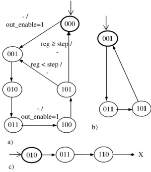
Consider the example FSM shown in Fig. 3a. Bold circle denotes the reset state, during two of the state transitions (000→001 and 011→100), its output register is loaded (i.e. out_enable=1). Now let us see the case when the least significant bit of the state register has the fault s-a-1. In that case a faulty FSM presented in Fig. 3b will result. This FSM contains only such legal states where the output register is not loaded (out_enable=0). Thus, the state register bit fault is only potentially testable. However, if the second bit of the state is s-a-1 (See Fig. 3c) then the faulty FSM will include a faulty state „110” and we cannot prove potential testability of this fault from the RT-level.
Fig. 3. a) A fault-free FSM, b) faulty FSM containing only legal states, c) faulty FSM with an illegal state 010
011 100
101 000
001
- / out_enable=1
011 101
001
a)
b)
c)
011 110
010 X
reg < step / - reg ≥ step /
- - /
out_enable=1
Status bits. The status bits enter from the datapath into the control part FSM. These signals represent the results of comparison operations and they control the selection of state transitions in the FSM. For example, the result of the comparison ‘reg < step’ is a status bit for the FSM in Fig. 3a.
Similar to state register bit faults, in case of stuck- at faults at status bits a faulty FSM will result where some of the branches will be excluded. Also, some of the legal states may become unreachable. However, illegal states can not result because of status bits faults. With the latter exception the condition for potential testability of status bit faults is identical to Condition 4.
4.3 Loop-counter faults
Loop-counters are blocks in RTL designs whose role is to implement fixed-length loops of the algorithm realized by the circuit. Output of a loop counter is a status bit (output of a comparison operator) signalling whether the loop has finished or not. Thus, identification of which loop-counters contain potentially testable faults is exactly identical to proving the potential testability for status bits.
In the experiments shown in Table 1, only the SOSQ and MULT benchmarks contain loop counters. However, loop-counter faults contribute to vast majority of potentially detectable faults found by the analysis. The main challenge however is to show from the potentially detectable status bits which logic-level faults inside the corresponding counters are also potentially detectable. The topic of such hierarchical fault mapping will be addressed by the future work.
5. Future work
As a future work we plan to implement the potential fault detection method and include the capabilities to an RTL test pattern generator. We also consider using the method in a hierarchical ATPG setup, where potentially detected faults from the high-level are mapped to the logic level.
6. Conclusions
The paper presented a new method for high-level identification of potentially testable initialization faults. Existing high-level fault models assume hard- detection and therefore are not capable of handling such initialization faults. Furthermore, three important classes of initialization faults were identified in the paper: reset faults, control part faults and loop-counter
faults. High-level methods for potential detection of faults of the respective classes were proposed.
Experiments presented in the paper show that potentially detectable initialization faults form a large subset of all the faults not testable by hard-detection. As a result of the proposed approach, both, the speed as well as the confidence level of sequential ATPG in terms of higher fault efficiency can be increased.
Acknowledgements
The research has been supported partly by EC FP 6 research project VERTIGO, Enterprise Estonia funded ELIKO Development Center, Estonian SF grant 7068, Estonian Center of Excellence program, EC REGPOT program and by Japan Society for the Promotion of Science (JSPS) under Grants-in-Aid for Scientific Research (B) (No. 20300018).
References
[1] H.-K.T Ma, S. Devadas, A.R. Newton, A. Sangiovanni- Vincentelli, “Test generation for sequential circuits”, IEEE Trans. on CAD, Vol. 7, No. 10 pp. 1081-1093, Oct. 1988. [2] T. M. Niermann, J. H. Patel, "HITEC: A test generation
package for sequential circuits", Proc. European Conf. Design Automation (EDAC), pp.214-218, 1991.
[3] D. Brahme, J. A. Abraham, "Functional Testing of Micro- processors", IEEE Trans. Comput., vol. C-33, 1984. [4] A. Gupta, J. R. Armstrong, "Functional fault modeling", 30th
ACM/IEEE DAC, pp. 720-726, 1985.
[5] F. Ferrandi, F. Fummi, D. Sciuto, “Implicit Test Generation for Behavioral VHDL Models,” Int. Test Conf., pp. 587-596, 1998.
[6] E. M. Rudnick, et al. "Sequential circuit test generation in a genetic algorithm framework", Proc. DAC, 1994.
[7] F. Corno, P. Prinetto, et al., "GATTO: A genetic algorithm for automatic test pattern generation for large synchronous sequential circuits", IEEE Trans. CAD, Aug. 1996. [8] M. S. Hiao, E. M. Rudnick, J. H. Patel, "Sequential circuit
test generation using dynamic state traversal", Proc. European Design and Test Conf., pp. 22-28, 1997.
[9] A. Giani, et al., “Efficient Spectral Techniques for Sequential ATPG,” Proc. IEEE DATE Conf., March 2001, pp. 204-208. [10] J. Raik, A. Krivenko, R. Ubar, M. Kruus. Hierarchical Identification of Untestable Faults in Sequential Circuits. IEEE Euromicro DSD, 2007.
[11] Jaan Raik Hideo Fujiwara Raimund Ubar Anna Krivenko, "Untestable Fault Identification in Sequential Circuits Using Model-Checking", IEEE 17th Asian Test Symposium, 2008.
[12] Turbo Tester test tools, URL: http://www.pld.ttu.ee/tt/ [13] J. Raik, R. Ubar, T. Viilukas, M. Jenihhin. Mixed
Hierarchical-Functional Fault Models for Targeting Sequential Cores. J. of Systems Architecture, Elsevier, 2008.