2
Servo motors
Options
Dimensions
MELSERVO
-
JN
Capacity selection software
•
MRZJW3-MOTSZ111E
Select the type of the machine.
Click the "Amplifier" button and select "MR-JN". Click the "Motor" button and select the motor.
Click the "Operation pattern" button to create the operation pattern. Input the specifications of the machine.
Click the "Calculate capacity" button.
The selected servo amplifier/servo motor model will be displayed.
You don’t need complex calculations anymore by using the capacity
selection software (MRZJW3-MOTSZ111E).
Machine-specific windows which apply to each machine are prepared.
The most suitable servo amplifier, servo motor (including the one with
electromagnetic brake or with reducer), and optional regeneration unit
can be selected automatically just by entering the constants and the
operation pattern of the machine.
•
Features
(1) User-defined operation patterns can be set. The operation pattern
can be selected from the position control mode operation or speed
control mode operation. The selected operation pattern can be also
displayed in the graph.
(2) The feedrate (or motor speed) and torque can be displayed in the
graph during the selection process.
* For details of the specifications, refer to p.36 of this catalog. * These are reference screens.
They may differ from the actual screens.
Servo Support Software (Easy introduction support)
START
The most suitable servo amplifier, servo motor,
and optional regeneration unit will be selected automatically.
Refer to the procedure of the capacity
selection software screen shown below.
Enter the machine specifications and the operation pattern into
machine-specific windows of the capacity selection software then execute the software.
Servo amplifiers
Servo motors
Options
Dimensions
Cautions
•
Features
(1) This software allows easy set up and tuning of the servo system with a personal computer.
(2) Multiple monitor functions
Graphic display functions are provided to display the servo motor status with the input signal triggers,
such as the command pulse, droop pulse and speed.
(3) Test operations with a personal computer
Test operation of the servo motors can be performed with a personal computer using multiple test
mode menus.
* For details of the specifications, refer to p.36 of this catalog.
Note: The screens on this page are for reference. They may differ from the actual screens.
MR Configurator
•
MRZJW3-SETUP221E (Setup software)
The MR Configurator makes it easy to perform, tuning, monitor display, diagnostics, reading and writing parameters, and test
operations with a personal computer. This software realizes a stable machine system, optimum control and short setup time.
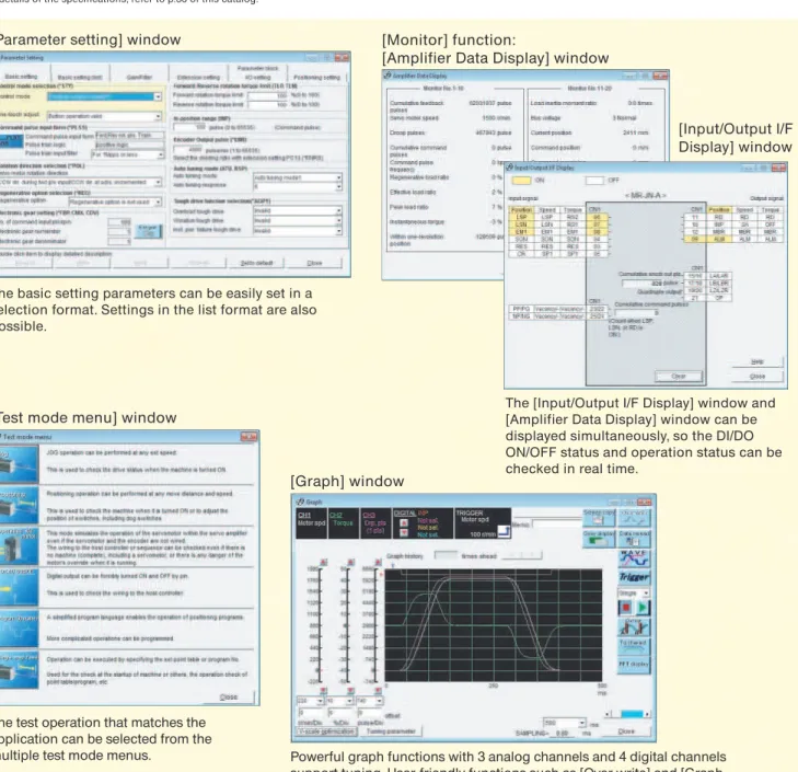
Powerful graph functions with 3 analog channels and 4 digital channels
support tuning. User-friendly functions such as [Over write] and [Graph
history] and a diverse waveform selection powerfully support user’s work.
Also, the [Gray display] function is provided for easy reading of printed data.
Data can be saved either in CSV or JPEG format.
[Graph] window
The basic setting parameters can be easily set in a
selection format. Settings in the list format are also
possible.
[Parameter setting] window
The [Input/Output I/F Display] window and
[Amplifier Data Display] window can be
displayed simultaneously, so the DI/DO
ON/OFF status and operation status can be
checked in real time.
[Monitor] function:
[Amplifier Data Display] window
[Input/Output I/F
Display] window
[Test mode menu] window
The test operation that matches the
application can be selected from the
multiple test mode menus.
Servo Support Software (Easy setup support)
Peripheral
Equipment
Servo Support
MELSERVO
-
JN
M R - J N 1 0
Mitsubishi general-purpose
AC servo amplifier
MELSERVO-JN series
A: General-purpose interface
List of
compatible servo motors
H F - K N 0 5
B
HF-KN series servo motors
Notes: 1. Refer to "Special Shaft End Specifications" in this catalog for the available models and detailed specifications.
Standard (straight shaft)
With key (Note 1)
D-cut (Note 1)
Note: HF-KN series does not have a geared servo motor. The geared servo motor is available in HF-KP series.
H F - K P 0 5
B
HF-KP series geared servo motors
None
Installed
Note: Refer to "ElectromagneticBrake Specifications" in this catalog for the available models and detailed specifications.
Note: Refer to "Geared Servo Motor Specifications" in this catalog for the available model and detailed specifications.
Notes: 1. Refer to "Special Shaft End Specifications" in this catalog for the available models and detailed specifications.
Standard (straight shaft)
With key (Note 1)
None
Installed
Note: Refer to "Electromagnetic BrakeSpecifications" in this catalog for detailed specifications.
Servo amplifiers
A
-3
3
Notes: 1. MR-JN-10A1 and -20A1 are available.
1-phase 200VAC
1-phase 100VAC (Note 1)
Symbol
None
1
Power supply
Symbol
10
20
40
HF-KN
053, 13
23
43
200VAC class
HF-KP
(with reducer)053, 13
23
43
Symbol
05
1
2
4
Rated output (kW)
0.05
0.1
0.2
0.4
Symbol
3
Symbol
None
K
D
Shaft end
Rated speed (r/min)
3000
Symbol
HF-KN
Servo motor series
Low inertia, small capacity* The servo motors above are under application for EN, UL and CSA standards. Contact your local sales office for more details.
Symbol
05
1
2
4
Rated output (kW)
0.05
0.1
0.2
0.4
Symbol
3
Symbol
None
B
Electromagnetic brake Symbol
G1
G5
G7
Reducer
For general industrial machines
Flange output type for precision application, flange mounting Shaft output type for precision application, flange mounting
Rated speed (r/min)
3000
Symbol
HF-KP
Servo motor series
Low inertia, small capacitySymbol
None
K
Shaft end
Symbol
None
B
Servo amplifiers
Servo motors
Options
Dimensions
Cautions
MELSERVO
-
JN
C P
FX3U programmable controller FX3UC programmable controller FX3G programmable controller
QD70P QD75P
QD70D QD75D
Servo amplifier
MR-JN- A (1)
Controllers
LD75P LD75D
Optional
regeneration
unit (option)
Control signal
(for operation panel)
Connected to a programmable controller's I/O port or a machine's operation panel.
MR-JN can be connected to a Mitsubishi controller or any pulse train output controller.
Install this unit in situations involving frequent regeneration and large load inertia moments.
One-touch tuning button
Display panel
Servo tuning is executed just by pressing this button.
Displays monitoring data, parameter and alarm.
Setting section
Parameter settings and monitoring etc. are executed with push buttons.
Monitoring, batch parameter entry and saving, graph display and test operation can be performed with MR Configurator (setup software) when connecting to user's personal computer.
Optional USB cable (MR-J3USBCBL3M) is necessary. Illuminates when the main
circuit power supply is charged. Power supply
1-phase 200VAC to 230VAC or 1-phase 100VAC
to 120VAC
Circuit protector Control circuit power supply 24VDC
R S
Used to protect the power supply line.
Used to turn off the servo amplifier's power when an alarm has been triggered.
Servo motor
(The picture is of HF-KN13.)
Motor power supply
cable (option)
Encoder cable
(option)
USB communication
(CN3) (option)
All signals can be wired via this terminal block.
Junction terminal block
(option)
Charge lamp
Notes: 1. Refer to "MR-JN- A INSTRUCTION MANUAL" for the actual connections. L1
L2 P C U V W
24
0
Magnetic
contactor
(MC)
Power factor
improvement
reactor
(FR-HAL)
Circuit
breaker
(NFB)
Pulses can be manually generated either by point table method or by program method
during the operation.
Manual pulse generator (MR-HDP01)
Manual pulse generator
(Option)
Peripheral equipment is connected to MR-JN-
A as described below.
Connectors, options, and other necessary equipment are available so that users can set up MR-JN-
A easily and begin using it right
away.
Connections with Peripheral Equipment
(Note 1)
Peripheral
Equipment
Servo Support
MELSERVO
-
JN
5% maximum
24VDC
0.5
10% maximum
10
24VDC 10% (required current capacity: 0.2A (Note 5))
Sine-wave PWM control/current control system
Built-in (Note 6)
1Mpps (when using differential receiver), 200kpps (when using open collector)
Encoder resolution: 131072 p/rev
Electronic gear A/B multiple, A: 1 to 65535, B: 1 to 65535, 1/50 < A/B < 500
0 to 65535 pulses (command pulse unit)
3 rotations
Set by parameters
Internal speed command 1:5000
Set by parameters
0.7 (1.5)
Interface power supply
Control system
Dynamic brake
Structure
Positioning mode (Note 8)
Mass (kg [lb])
Safety features
Rated voltage
Rated current (A)
Voltage/frequency (Note 1, 2)
Rated current (A)
Permissible voltage fluctuation
Permissible frequency fluctuation
Voltage
Rated current (A)
Permissible voltage fluctuation
Power consumption (W)
Maximum input pulse frequency
Positioning feedback pulse
Command pulse multiple
Positioning complete width setting
Excess error
Torque limit
Ambient temperature (Note 7)
Ambient humidity
Atmosphere
Elevation
Vibration
Speed control range
Speed command input
Speed fluctuation rate
Torque limit
Torque command input
Speed limit
Tolerable regenerative power of built-in
regenerative resistor (W) (Note 3, 4)
Main
circuit
power
supply
Servo amplifier model
0.6 (1.3)
Set by parameters
Set by parameters
Set by parameters
Point table method, Program method
Natural-cooling open (IP rating: IP20)
0 to 55 C (32 to 131 F) (non freezing), storage: -20 to 65 C (-4 to 149 F) (non freezing)
90% RH maximum (non condensing), storage: 90% RH maximum (non condensing)
Indoors (no direct sunlight); no corrosive gas, inflammable gas, oil mist or dust
1000m or less above sea level
5.9m/s
2or less at 10 to 55Hz (directions of X, Y and Z axes)
MR-JN-40A
MR-JN-10A1
MR-JN-20A1
MR-JN-20A
MR-JN-10A
10
10
2.4
4.5
1.5
1.6
2.8
1.1
1.6
1.1
10
3.0
5.0
0.6 (1.3)
0.6 (1.3)
-
-0.6 (1.3)
Output
1-phase 200VAC to 230VAC 50/60Hz
1-phase 170VAC to 253VAC
1-phase 100VAC to 120VAC 50/60Hz
1-phase 85VAC to 132VAC
3-phase 170VAC
Overcurrent shutdown, regeneration overvoltage shutdown, overload shutdown (electronic thermal), servo
motor overheat protection, encoder fault protection, regeneration fault protection, undervoltage/sudden power
outage protection, overspeed protection, excess error protection
0.01% maximum (load fluctuation 0 to 100%)
0% (power fluctuation 10%)
Control
circuit
power
supply
Internal
speed
control
mode
Internal
torque
control
mode
Position
control
mode
Environ-ment
Notes: 1. Rated output and speed of a servo motor are applicable when the servo amplifier, combined with the servo motor, is operated within the specified power supply voltage and frequency. Torque drops when the power supply voltage is below the specified value.
2. For torque characteristics when combined with a servo motor, refer to "Servo Motor Torque Characteristics" in this catalog. 3. Optimal regenerative resistor varies for each system. Select the most suitable regenerative resistor by using the capacity selection software. 4. Refer to "Options
•
Optional regeneration unit" in this catalog for the tolerable regenerative power (W).5. 0.2A is the value when all of the input/output points are used. The current capacity can be stepped down according to the number of input/output points in use. Refer to "MR-JN-A INSTRUCTION MANUAL" for details.
6. When using the built-in dynamic brake, refer to "MR-JN-A INSTRUCTION MANUAL" for the permissible load to motor inertia moment ratio.
7. The servo amplifier can be installed closely. In this case, keep the ambient temperature within 0 to 45°C (32 to 113°F), or use the servo amplifier at 75% or less of the effective load rate.
8. Servo amplifier with software version B0 or above is required for the positioning function.
Servo amplifiers
Servo motors
Options
Dimensions
Cautions
MELSERVO
-
JN
USB cable
MR-J3USBCBL3M MR Configurator (Setup software) MRZJW3-SETUP221E Personal computer
CN3
24V0V (Note 4)
CNP2
24VDC power supply for control circuit
Circuit protector
10m maximum Forced stop
Forward rotation stroke end Reset Servo-on
Malfunction Electromagnetic brake interlock
(Note 9) (Note 8)
(Note 10)
(Note 4, 7, 8)
(Note 13) (Note 15) (Note 15) (Note 13) (Note 6) (Note 11) 10m maximum R A 1 R A 2
CN1
CN1
24VDC power supplyfor interface
Encoder A-phase pulse (differential line driver)
10m maximum
PLATE (Note 12)
Encoder B-phase pulse (differential line driver) Encoder Z-phase pulse (differential line driver)
2m (Note 14) Programmable controller
FX3U- MT/ES Programmable controller power supply 6 7 8 4 3 9 12 1 13 2 19 20 15 16 17 18 14 21 11 23 25 5 DOCOM OPC LZ LZR LA LAR LB LBR SD OP LG RD 10 INP PP NP CR DICOM EM1 SON RES LSP LSN ALM MBR N 0V 24V S/S X00 X X L COM1 Y000 COM COM2 Y004 Y
Notes: 1. Disconnect the wires for the built-in regenerative resistor (P and C) and remove the resistor from the servo amplifier when connecting the optional regeneration unit externally. 2. This is for the servo motor with electromagnetic brake. The electromagnetic brake terminals (B1, B2) do not have polarity.
3. Connect the ground wire to the cabinet protective earth (PE) terminal via the servo amplifier protective earth (PE) terminal for grounding. 4. Do not connect the 0V of 24VDC power supply to the servo amplifier protective earth (PE) terminal.
5. The signals shown are applicable when using a two-wire type encoder cable. Refer to "MR-JN- A INSTRUCTION MANUAL" for four-wire type.
6. Do not reverse the diode's direction. Connecting it backwards may cause the servo amplifier to malfunction such that the signals are not output, and the forced stop and other safety circuits are inoperable.
7. Use the power supply 24VDC 10% (required current capacity: 0.2A). 0.2A is the value when all of the input/output points are used.
Note that the current capacity can be stepped down according to the number of input/output points in use. Refer to "MR-JN- A INSTRUCTION MANUAL" for details. 8. Use the enhanced insulation power supply for the external power supply 24VDC. Do not use the 24VDC interface and control circuit power supplies for the electromagnetic brake. Provide a power supply designed exclusively for the electromagnetic brake.
9. Always turn on the forced stop (EM1) signal (normally closed contact) before starting the operation. If not, the operation will not start.
10. Always turn on the forward and reverse rotation stroke end (LSP/LSN) signals (normally closed contact) before starting the operation. If not, the commands will not be accepted. 11. The malfunction (ALM) signal (normally closed contact) is conducted to DOCOM in normal alarm-free condition.
12. Connect the shield wire securely to the plate inside the connector (ground plate).
13. This is applicable when the setting of the programmable controller is for the first axis. For the second or third axis, the number changes. 14. It is recommended that the connection be 2m or shorter because an open-collector system is used.
15. Signal names are different for FX3U-16MT/ES: COM1 will be COM0 and COM2 will be COM4. Reverse rotation stroke end
Servo amplifier
MR-JN- A (1)
L1 L2 NFB MC Main circuit power supply 1-phase 200 to 230VAC
or 1-phase 100 to 120VAC
Optional regeneration unit (Note 1) P C
CNP1
CNP1
Built-in regenerative resistorCN2
(Note 3) 1 2 3 4 PLATE 2 3 4 1 1 2Servo motor
HF-KN/KP series
M
Electro- magnetic brake (Note 2) Encoder 24VDC for electromagnetic brake (Note 4, 8)(Note 5)
B (Note 3, 4)
U V W P5 LG MR MRR SD P5 LG MR MRR SD U V W B1 B2 RA
Contacts must be open when the servo on (SON) or the electromagnetic brake interlock (MBR) signal turns off. Contacts must be
open by an external emergency stop switch.
U
•
Connection example to FX
3U
Standard Wiring Diagram: Position Control Operation
Peripheral
Equipment
Servo Support
MELSERVO
-
JN
Notes: 1. Disconnect the wires for the built-in regenerative resistor (P and C) and remove the resistor from the servo amplifier when connecting the optional regeneration unit externally. 2. This is for the servo motor with electromagnetic brake. The electromagnetic brake terminals (B1, B2) do not have polarity.
3. Connect the ground wire to the cabinet protective earth (PE) terminal via the servo amplifier protective earth (PE) terminal for grounding. 4. Do not connect the 0V of 24VDC power supply to the servo amplifier protective earth (PE) terminal.
5. The signals shown are applicable when using a two-wire type encoder cable. Refer to "MR-JN- A INSTRUCTION MANUAL" for four-wire type.
6. Do not reverse the diode's direction. Connecting it backwards may cause the servo amplifier to malfunction such that the signals are not output, and the forced stop and other safety circuits are inoperable.
7. Use the power supply 24VDC 10% (required current capacity: 0.2A). 0.2A is the value when all of the input/output points are used.
Note that the current capacity can be stepped down according to the number of input/output points in use. Refer to "MR-JN- A INSTRUCTION MANUAL" for details. 8. Use the enhanced insulation power supply for the external power supply 24VDC. Do not use the 24VDC interface and control circuit power supplies for the electromagnetic brake. Provide a power supply designed exclusively for the electromagnetic brake.
9. Always turn on the forced stop (EM1) signal (normally closed contact) before starting the operation. If not, the operation will not start.
10. Always turn on the forward and reverse rotation stroke end (LSP, LSN) signals (normally closed contact) before starting the operation. If not, the commands will not be accepted. 11. The malfunction (ALM) signal (normally closed contact) is conducted to DOCOM in normal alarm-free condition.
12. Connect the shield wire securely to the plate inside the connector (ground plate).
13. This connection is not necessary for QD75D positioning module. Note that the connection between LG and control common terminal is recommended for some positioning modules to improve noise immunity.
14. This is for sink wiring. Source wiring is also possible. Refer to "MR-JN- A INSTRUCTION MANUAL" for details. USB cable MR-J3USBCBL3M MR Configurator (Setup software) MRZJW3-SETUP221E Personal computer
CN3
10m maximum Forced stopForward rotation stroke end Reset Servo-on
Malfunction In-position Electromagnetic brake interlock
(Note 9) (Note 8) (Note 10) (Note 6) (Note 11) 10m maximum R A 1 R A 2 R A 3
CN1
CN1
24VDC power supplyfor interface
Encoder A-phase pulse (differential line driver)
(Note 13) 10m maximum 2m maximum Name Control common P
ositioning module QD75D
PLATE (Note 14)
Encoder B-phase pulse (differential line driver)
Control common Control common
Encoder Z-phase pulse (open collector)
(Note 12)
CNP2
24VDC power supplyfor control circuit
24V 10 6 7 8 4 3 9 12 1 13 5 11 23 22 25 24 19 20 14 15 16 17 14 18 21 INP EM1 SON RES LSP LSN ALM MBR DICOM DOCOM CR RD PP PG NP NG LZ LZR LG LA LAR LB OP LBR LG SD Pin No. 14 13 12 11 15 16 17 10 18 9 CLEAR COM CLEAR RDY COM READY PULSE F+ PULSE F-PULSE R+ PULSE R-PG0 PG0 COM Circuit protector
0V (Note 4)
(Note 4, 7, 8)
Reverse rotation stroke end
Servo amplifier
MR-JN- A (1)
L1 L2 NFB MC Main circuit power supply 1-phase 200 to 230VAC
or 1-phase 100 to 120VAC
Optional regeneration unit (Note 1) P C
CNP1
CNP1
CN2
(Note 3) 1 2 3 4 PLATEM
Electro- magnetic brake (Note 2) Encoder 24VDC for electromagnetic brake (Note 4, 8)(Note 5) B
Servo motor
HF-KN/KP series
2 3 4 1 1 2 U V W P5 LG MR MRR SD P5 LG MR MRR SD U V W Built-in regenerative resistor(Note 3, 4)
B1
B2 RA
Contacts must be open when the servo on (SON) or the electromagnetic brake interlock (MBR) signal turns off. Contacts must be
open by an external emergency stop switch.
U
•
Connection example to QD75D
Servo amplifiers
Servo motors
Options
Dimensions
Cautions
Standard Wiring Diagram: Speed Control Operation
(Note 1)
1. MR-JN- A supports only operations by internal speed command.
2. Disconnect the wires for the built-in regenerative resistor (P and C) and remove the resistor from the servo amplifier when connecting the optional regeneration unit externally. 3. This is for the servo motor with electromagnetic brake. The electromagnetic brake terminals (B1, B2) do not have polarity.
4. Connect the ground wire to the cabinet protective earth (PE) terminal via the servo amplifier protective earth (PE) terminal for grounding. 5. Do not connect the 0V of 24VDC power supply to the servo amplifier protective earth (PE) terminal.
6. The signals shown are applicable when using a two-wire type encoder cable. Refer to "MR-JN- A INSTRUCTION MANUAL" for four-wire type.
7. Do not reverse the diode's direction. Connecting it backwards may cause the servo amplifier to malfunction such that the signals are not output, and the forced stop and other safety circuits are inoperable.
8. Use the power supply 24VDC 10% (required current capacity: 0.2A). 0.2A is the value when all of the input/output points are used.
Note that the current capacity can be stepped down according to the number of input/output points in use. Refer to "MR-JN- A INSTRUCTION MANUAL" for details. 9. Use the enhanced insulation power supply for the external power supply 24VDC. Do not use the 24VDC interface and control circuit power supplies for the electromagnetic brake. Provide a power supply designed exclusively for the electromagnetic brake.
10. Always turn on the forced stop (EM1) signal (normally closed contact) before starting the operation. If not, the operation will not start. 11. The malfunction (ALM) signal (normally closed contact) is conducted to DOCOM in normal alarm-free condition.
12. Connect the shield wire securely to the plate inside the connector (ground plate).
13. This is for sink wiring. Source wiring is also possible. Refer to "MR-JN- A INSTRUCTION MANUAL" for details. Notes: USB cable MR-J3USBCBL3M MR Configurator (Setup software) MRZJW3-SETUP221E Personal computer
Servo amplifier
MR-JN- A (1)
CN3
10m maximumForced stop
Speed selection 1 Forward rotation start Reverse rotation start Reset Servo-on
Malfunction Electromagnetic brake interlock Ready Speed reached (Note 10) (Note 9) (Note 7) 10m maximum (Note 13) R A 1 R A 2 R A 3
CN1
24VDC power supply for interface R A 4 L1 L2 NFB MC Main circuit power supply 1-phase 200 to 230VAC
or 1-phase 100 to 120VAC
Optional regeneration unit (Note 2) 24V P C
CNP1
CNP1
CNP2
CN2
(Note 4) 1 2 3 4 PLATE 2 3 4 1 1 2M
Electro- magnetic brake (Note 3) Encoder 24VDC for electromagnetic brake (Note 5, 9)(Note 6)
B 24VDC power supply
for control circuit
Control common Control common Encoder Z-phase pulse
(differential line driver) Encoder A-phase pulse (differential line driver)
Encoder B-phase pulse (differential line driver)
Encoder Z-phase pulse
(open collector) PLATE
10m maximum 2m maximum (Note 12)
Servo motor
HF-KN/KP series
U V W P5 LG MR MRR SD P5 LG MR MRR SD U V W 12 5 6 7 8 4 3 9 11 10 1 13 19 20 15 16 17 18 14 21 MBR EM1 SON RES SP1 ST1 ST2 ALM RD SA DICOM DOCOM LZ LZR LA LAR LB LBR LG OP SD Circuit protector (Note 11)(Note 5, 8, 9)
(Note 4, 5)
0V (Note 5)
B1
B2 RA
Contacts must be open when the servo on (SON) or the electromagnetic brake interlock (MBR) signal turns off. Contacts must be
open by an external emergency stop switch.
U
Built-in regenerative resistor
•
Connection example
Peripheral
Equipment
Servo Support
Standard Wiring Diagram: Torque Control Operation
(Note 1)
Notes: 1. MR-JN- A supports only operations by internal torque command.
2. Disconnect the wires for the built-in regenerative resistor (P and C) and remove the resistor from the servo amplifier when connecting the optional regeneration unit externally. 3. This is for the servo motor with electromagnetic brake. The electromagnetic brake terminals (B1, B2) do not have polarity.
4. Connect the ground wire to the cabinet protective earth (PE) terminal via the servo amplifier protective earth (PE) terminal for grounding. 5. Do not connect the 0V of 24VDC power supply to the servo amplifier protective earth (PE) terminal.
6. The signals shown are applicable when using a two-wire type encoder cable. Refer to "MR-JN- A INSTRUCTION MANUAL" for four-wire type.
7. Do not reverse the diode's direction. Connecting it backwards may cause the servo amplifier to malfunction such that the signals are not output, and the forced stop and other safety circuits are inoperable.
8. Use the power supply 24VDC 10% (required current capacity: 0.2A). 0.2A is the value when all of the input/output points are used.
Note that the current capacity can be stepped down according to the number of input/output points in use. Refer to "MR-JN- A INSTRUCTION MANUAL" for details. 9. Use the enhanced insulation power supply for the external power supply 24VDC. Do not use the 24VDC interface and control circuit power supplies for the electromagnetic brake. Provide a power supply designed exclusively for the electromagnetic brake.
10. Always turn on the forced stop (EM1) signal (normally closed contact) before starting the operation. If not, the operation will not start. 11. The malfunction (ALM) signal (normally closed contact) is conducted to DOCOM in normal alarm-free condition.
12. Connect the shield wire securely to the plate inside the connector (ground plate).
13. This is for sink wiring. Source wiring is also possible. Refer to "MR-JN- A INSTRUCTION MANUAL" for details. USB cable MR-J3USBCBL3M MR Configurator (Setup software) MRZJW3-SETUP221E Personal computer
Servo amplifier
MR-JN- A (1)
CN3
10m maximumForced stop
Speed limit 1 Forward rotation selection Reverse rotation selection Reset Servo-on
Malfunction Electromagnetic brake interlock Ready (Note 10) (Note 9) (Note 7) 10m maximum (Note 13) R A 1 R A 2 R A 3
CN1
24VDC power supply for interface L1 L2 NFB MC Main circuit power supply 1-phase 200 to 230VAC
or 1-phase 100 to 120VAC
Optional regeneration unit (Note 2) 24V P C
CNP1
CNP1
CNP2
CN2
(Note 4) 1 2 3 4 PLATEM
Electro- magnetic brake (Note 3) Encoder 24VDC for electromagnetic brake (Note 5, 9)(Note 6)
B 24VDC power supply
for control circuit
Control common Control common Encoder Z-phase pulse (differential line driver) Encoder A-phase pulse (differential line driver)
Encoder B-phase pulse (differential line driver)
Encoder Z-phase pulse
(open collector) PLATE
10m maximum 2m maximum (Note 12)
Servo motor
HF-KN/KP series
2 3 4 1 1 2 U V W U V W P5 LG MR MRR SD P5 LG MR MRR SD 12 5 7 6 8 4 3 9 11 1 13 19 20 15 16 17 18 14 21 MBR EM1 SON RES SP1 RS1 RS2 ALM RD DICOM DOCOM LZ LZR LA LAR LB LBR LG OP SD Circuit protector (Note 11)(Note 5, 8, 9)
(Note 4, 5)
0V (Note 5)
B1
B2 RA
Contacts must be open when the servo on (SON) or the electromagnetic brake interlock (MBR) signal turns off. Contacts must be
open by an external emergency stop switch.
U
Built-in regenerative resistor
•
Connection example
MELSERVO
-
JN
Item
Position data
Acceleration time constant Deceleration time constant Dwell time
Auxiliary function
Setting range
-999999 to 999999
Unit
10STMµm
0
to permissible 0 to 20000
0 to 20000
0 to 3
r/min
ms ms ms
Description
Absolute value command method
Sets the address. STM is the ratio for the data.
Incremental value command method
Sets the movement amount. STM is the ratio for the data. Sets the command speed for the servo motor used for positioning.
Sets the acceleration time constant. (Note 2) Sets the deceleration time constant. (Note 2) Runs the next point table after the set dwell time.
Absolute value command method
0: Positions and stops (waits for start signal). 1: Continues operation for the next point table without stopping.
Incremental value command method
2: Positions and stops (waits for start signal). 3: Continues operation for the next point table without stopping.
Point table No. 1 2 7 1000 2000 3000 2000 1600 3000 200 100 100 200 100 100 0 0 0 1 0 2 Position data Servo motor speed Acceler-ation time constant Deceler-ation time constant
Dwell time
Auxiliary function
If the point table No.1's auxiliary function is 1 or 3, continuous positioning operation is carried out based on the point table as shown in the " Auxiliary function 1 or 3" below.
If the point table No.1's auxiliary function is 0 or 2,
a start signal must be issued as shown in " Auxiliary function 0 or 2" below.
Auxiliary function 1 or 3 Auxiliary function 0 or 2
Speed Position address Start signal 1000 2000 Point table No.1 Point table No.2 Speed Position address Start signal Point table No.1 Point table No.2
0 1000 2000
0 to 999999
0
to permissible 0 to 20000 0 to 20000 0 to 20000
Sets the command speed for the servo motor used for positioning.
Runs the next point table after the set dwell time. Sets the movement amount. STM is the ratio for the data.
0: Positions and stops (waits for start signal). 1: Continues operation for the next point table without stopping.
1 2 7 1000 1000 500 2000 1600 3000 200 100 100 200 100 100 0 0 0 1 0 0 If the point table No.1's auxiliary function is 1, continuous positioning operation is carried out based on the point table as shown in the " Auxiliary function 1" below.
If the point table No.1's auxiliary function is 0, a start signal must be issued as shown in " Auxiliary function 0" below.
Notes: 1. Servo amplifier with software version B0 or above is required for the positioning function. 2. S-pattern acceleration/deceleration time constant is set by the servo amplifier's parameter.
Set position and speed data in the point ta
b
le
b
eforehand.
Positioning operation is performed after selecting the point ta
b
le n
u
m
b
er
w
ith an external interface signal.
Point table:
The follo
w
ing t
w
o types of point ta
b
les are a
v
aila
b
le.
(1) Absolute value command method:
Mo
v
es to the address (a
b
sol
u
te
v
al
u
e)
b
ased on the home position.
(Example of setting point ta
b
le data)
(2) Incremental value command method:
Mo
v
es from the c
u
rrent
v
al
u
e according to the set position data
(Example of setting point ta
b
le data)
Positionin
g
function: Point table
m
ethod
(Note 1)
Servo motor speed
0 to 20000
-0
Sets the acceleration time constant. (Note 2) Sets the deceleration time constant. (Note 2)
0 and 1
Auxiliary function 1 Auxiliary function 0
Speed Position address Start signal 1000 2000 Point table No.1 Point table No.2 Speed Position address Start signal Point table No.1 Point table No.2
0 1000 2000
0
10STMµm
r/min ms ms ms
-Item Position dataAcceleration time constant Deceleration time constant Dwell time
Auxiliary function
Setting range Unit Description Point
table No.
Position data
Servo motor speed Acceler-ation time constant Deceler-ation time constant
Dwell time
Auxiliary function
MELSERVO
-
JN
Item
Description
DIO (
N
ote 1)
Positions according to the specification of the point ta
b
le
N
o. (7 points)
Signed a
b
sol
u
te
v
al
u
e command system, increment
v
al
u
e command system
Point ta
b
le n
u
m
b
er inp
u
t
Each positioning operation
b
ased on position and speed commands.
Set in point ta
b
le. One-point feed length setting range: 1µm to 999999 10 µm. (
N
ote 2)
Man
u
al feed
b
y man
u
al p
u
lse generator.
Command p
u
lse m
u
ltiplication: 1, 10 or 100 is selecta
b
le
b
y the parameter.
Ret
u
rns to home position
u
pon Z-phase p
u
lse co
u
nt after passing thro
u
gh proximity dog.
Direction for ret
u
rn to home position selecta
b
le. Home position shift amo
u
nt and home position address setta
b
le.
A
u
tomatic retreat on dog
b
ack to home position and a
u
tomatic stroke retreat f
u
nction.
Ret
u
rns to home position
u
pon Z-phase p
u
lse co
u
nt after to
u
ching proximity dog.
Direction for ret
u
rn to home position selecta
b
le. Home position shift amo
u
nt and home position address setta
b
le.
A
u
tomatic retreat on dog
b
ack to home position and a
u
tomatic stroke retreat f
u
nction.
Ret
u
rns to home position
w
ith respect to the rear end of a proximity dog.
Direction for ret
u
rn to home position selecta
b
le. Home position shift amo
u
nt and home position address setta
b
le.
A
u
tomatic retreat on dog
b
ack to home position and a
u
tomatic stroke retreat f
u
nction.
Ret
u
rns to home position
w
ith respect to the front end of a proximity dog.
Direction for ret
u
rn to home position selecta
b
le. Home position shift amo
u
nt and home position address setta
b
le.
A
u
tomatic retreat on dog
b
ack to home position and a
u
tomatic stroke retreat f
u
nction.
Ret
u
rns to home position
u
pon the first Z-phase p
u
lse
w
ith respect to the front end of a proximity dog.
Direction for ret
u
rn to home position selecta
b
le. Home position shift amo
u
nt and home position address setta
b
le.
A
u
tomatic retreat on dog
b
ack to home position and a
u
tomatic stroke retreat f
u
nction.
Ret
u
rns to home position
w
itho
u
t dog. Sets any position as home position
u
sing man
u
al operation, etc.
Home position address setta
b
le.
Ret
u
rns to home position
u
pon hitting end of stroke.
Direction for ret
u
rn to home position selecta
b
le. Home position address setta
b
le.
Uses position
w
here the ser
v
o on (SO
N
) signal t
u
rns O
N
as home position. Home position address setta
b
le.
Command method
Command interface
Operating specification
Inp
u
t positioning
command
System
Inches
u
pon inp
u
t
b
ased on speed commands set
b
y a parameter.
Point ta
b
le
JOG
Man
u
al p
u
lse
generator
Dog type
Co
u
nt type
Data set type
Stopper type
Ignore home
(Ser
v
o-on position
as home position)
Point ta
b
le
N
o. inp
u
t
A
u
tomatic
operation
mode
Man
u
al
operation
mode
Home
position
ret
u
rn
mode
Command and Operation Mode
Dog type rear
end reference
Dog cradle type
Co
u
nt type front
end reference
Notes: 1. The command interface will be compatible with pulse train command by using manual pulse generator (MR-HDP01). 2. STM is the ratio for the data. It can be changed by parameter.
Oper
ation mode
STM
MELSERVO
-
JN
Servo amplifiers
Servo motors
Options
Dimensions
Cautions
USB cable MR-J3USBCBL3MC
N
3
10m maximum Positioning complete (Note 9) (Note 13) (Note 8) 10m maximum (Note 12)
C
N
1
L1 L2 NFB MC 24V P C
C
N
P1
C
N
P1
C
N
P2
C
N
2
(Note 3) 1 2 3 4 PLATE 2 3 4 1 1 2
M
Electro- magnetic brake (Note 2) (Note 5) B 10m maximum 2m maximum (Note 11) (Note 10)Ser
v
o motor
HF-K
N
/KP series
P5 LG MR MRR SD P5 LG MR MRR SD U V W U V W 12 5 6 7 8 4 3 23 25 9 11 10 1 13 19 20 15 16 17 18 14 21 MBR EM1 SON MD0 DI0 DI1 DOG ST1 ST2 ALM RD MEND DICOM 2 OPC DOCOM LZ LZR LA LAR LB LBR LG OP SD
0V (Note 4)
(Note 3, 4)
(Note 4, 7, 8)
Connection example
(Note 6) R A 1 R A 2 R A 3 R A 4 (Note 13)24VDC for electromagnetic
brake (Note 4, 8)
Encoder
Notes: 1. Disconnect the wires for the built-in regenerative resistor (P and C) and remove the resistor from the servo amplifier when connecting the optional regeneration unit externally. 2. This is for the servo motor with electromagnetic brake. The electromagnetic brake terminals (B1, B2) do not have polarity.
3. Connect the ground wire to the cabinet protective earth (PE) terminal via the servo amplifier protective earth (PE) terminal for grounding. 4. Do not connect the 0V of 24VDC power supply to the servo amplifier protective earth (PE) terminal.
5. The signals shown are applicable when using a two-wire type encoder cable. Refer to "MR-JN- A INSTRUCTION MANUAL" for four-wire type.
6. Do not reverse the diode's direction. Connecting it backwards may cause the servo amplifier to malfunction such that the signals are not output, and the forced stop and other safety circuits are inoperable.
7. Use the power supply 24VDC 10% (required current capacity: 0.2A). 0.2A is the value when all of the input/output points are used.
Note that the current capacity can be stepped down according to the number of input/output points in use. Refer to "MR-JN- A INSTRUCTION MANUAL" for details.
8. Use the enhanced insulation power supply for the external power supply 24VDC. Do not use the 24VDC interface and control circuit power supplies for the electromagnetic
brake. Provide a power supply designed exclusively for the electromagnetic brake.
9. Always turn on the forced stop (EM1) signal (normally closed contact) before starting the operation. If not, the operation will not start. 10. The malfunction (ALM) signal (normally closed contact) is conducted to DOCOM in normal alarm-free condition.
11. Connect the shield wire securely to the plate inside the connector (ground plate).
12. This is for sink wiring. Source wiring is also possible. Refer to "MR-JN- A INSTRUCTION MANUAL" for details. 13. Manual pulse generator can be used by setting a parameter. Refer to "MR-JN- A INSTRUCTION MANUAL" for details.
PLATE
MR Configurator (Setup software) MRZJW3-SETUP221E Personal computer
Ser
v
o amplifier
MR-J
N
- A (1)
Forward rotation selection Reverse rotation selection Servo-on
Malfunction Electromagnetic brake interlock Ready
24VDC power supply for interface Main circuit power supply
1-phase 200 to 230VAC
or 1-phase 100 to 120VAC
Optional regeneration unit (Note 1)
24VDC power supply for control circuit
Control common Control common Encoder Z-phase pulse (differential line driver) Encoder A-phase pulse (differential line driver) Encoder B-phase pulse (differential line driver)
Encoder Z-phase pulse (open collector) Circuit protector B1 B2 RA
Contacts must be open
when the servo on (SON) or the electromagnetic
brake interlock (MBR) signal turns off. Contacts must be
open by an external emergency stop switch.
U
Forced stop
Automatic/manual selection
MELSERVO
-
JN
Create position data, ser
v
o motor speed, acceleration and deceleration time constants and so on as programs
b
eforehand.
Positioning operation is performed
b
y selecting the created Program
N
o.
w
ith an external interface signal.
Program method ena
b
les more complex positioning operation than point ta
b
le method. MR Config
u
rator (Set
u
p soft
w
are)
is re
qu
ired to create a program. (
N
ote 7)
Command list (Note 6)
7. MRZJW3-SETUP221E with software version C4 or above is compatible with creating a program. 8. Servo amplifier with software version B0 or above is required for the positioning function.
Positioning function: Program method
(Note 8)
SPN
(Note 1)
STA (Note 2) STB (Note 2)
STC(Note 2)
STD(Note 2)
MOV
MOVA
MOVI
MOVIA
SYNC (Note 3) OUTON (Note 3) OUTOF (Note 3) TRIP (Note 3) TRIPI (Note 3) ITP (Note 3, 4)
COUNT (Note 3) FOR NEXT TIM ZRT TIMES STOP
Servo motor speed
Acceleration time constant Deceleration time constant Acceleration and deceleration time constants S-pattern acceleration and deceleration time constants Absolute value move command
Absolute value continuous move
command Incremental value
move command Incremental value
continuous move command Waiting for external signal to switch ON External signal
ON output
Absolute value passage point specification Incremental value
passage point specification
Interrupt positioning
External pulse count
Step repeat command
Program count command
Program stop Dwell Home position return
External signal OFF output
SPN (setting)
STA (setting) STB (setting)
STC (setting)
STD (setting)
MOV (setting)
MOVA (setting)
MOVI (setting)
MOVIA (setting)
SYNC (setting)
OUTON (setting)
OUTOF (setting)
TRIP (setting)
TRIPI (setting)
ITP (setting)
COUNT (setting)
FOR (setting) NEXT TIM (setting) ZRT TIMES (setting) STOP r/min ms ms ms ms — — —
pulse
times ms — times — 0 to
permissible speed
Command Name Setting Settingrange Unit Description
— — (Note 5) (Note 5) (Note 5) (Note 5) (Note 5) (Note 5)
Notes:1. The [SPN] command is valid when the [MOV], [MOVA], [MOVI], or [MOVIA] command is executed. 2. The [STA], [STB], [STC], and [STD] commands are valid when the [MOV] or [MOVI] command is executed.
3. The [SYNC], [OUTON], [OUTOF], [TRIP], [TRIPI], [ITP], and [COUNT] commands are valid even while an instruction is output.
4. If the remaining distance equals to the setting value or less, the servo motor is not running, or the servo motor is decelerating, the [ITP] command is skipped and control goes to the next step.
5. STM is the ratio for the data. It can be changed by parameter.
6. For the content of each command, refer to "MR-JN- A INSTRUCTION MANUAL". 0 to 20000
0 to 20000
0 to 20000
0 to 100
–999999 to 999999 1 0 to 999999 0, 1 to 10000
1 to 20000
0, 1 to 10000
Sets the command speed of the servo motor for positioning. The setting value must not exceed the permissible speed of the servo motor used.
Sets the acceleration time constant. Sets the deceleration time constant.
Sets the acceleration and deceleration time constants.
Sets the S-pattern acceleration and deceleration time constants.
Moves according to the value set as an absolute value.
Moves continuously according to the value set as an absolute value. Be sure to use this command together with the [MOV] command.
Moves according to the value set as an incremental value.
Moves continuously according to the value set as an incremental value. Be sure to use this command together with the [MOVI] command.
Turns OFF the program output 1 (OUT1) which was turned ONby the [OUTON] command.
When the motor passes through the current position set, the next step is executed.
When the value of the pulse counter exceeds the count value set in the [COUNT] command, the next step is executed. Setting [COUNT (0)] clears the pulse counter to zero.
Repeats the steps between [FOR (setting value)] and [NEXT] commands for the number of times set.
If zero is set, the steps are repeated unlimitedly. Waits for the next step until the set time passes. Executes a manual home position return.
Sets the number of program execution by writing [TIMES (setting value)] command on the beginning of the program. If zero is set, the program is repeated unlimitedly. Stops the program being executed. Be sure to write this command in the final line.
When the motor moves for the moving distance set by the [TRIPI] command after the [MOVI] and/or [MOVIA] commands is performed, the next step is executed. Be sure to write this command after the [MOVI] and/or [MOVIA] commands.
Stops the next step until the program input 1 (PI1) is turned ON after the synchronous output (SOUT) command is output.
When the interrupt signal is ON, the motor moves for the distance set by this command, and it stops. Use this command after the [SYNC] command in combination. Turns ON the program output 1 (OUT1).
10STMµm
–999999 to 999999 –999999 to 999999 –999999 to 999999 1 1 –999999 to 999999 –999999 to 999999 –999999 to 999999
10STMµm
10STMµm
10STMµm
10STMµm
10STMµm
W
hen exec
u
ting t
w
o types of operations
w
hich ha
v
e the same ser
v
o motor speed, the same acceleration and deceleration time
constants and the different mo
v
e commands:
Example 1
Program
(
N
ote 1)
SP
N
(3000)
STA (200)
STB (300)
MO
V
(1000)
TIM (100)
MO
V
(2500)
STOP
Ser
v
o motor speed 3000 (r/min)
Acceleration time constant 200 (ms)
Deceleration time constant 300 (ms)
A
b
sol
u
te
v
al
u
e mo
v
e command 1000 ( )
D
w
ell 100 (ms)
A
b
sol
u
te
v
al
u
e mo
v
e command 2500 ( )
Program stop
Speed
Position address 0
1000
2500
A
b
sol
u
te
v
al
u
e
mo
v
e command
(1000 )
A
b
sol
u
te
v
al
u
e
mo
v
e command
(2500 )
D
w
ell
(100ms)
Notes: 1. The values set as steps , , and are valid as long as they are not set again. 2. The setting value is the time elapsing from the stop of the servo motor to the rated speed. 3. The setting value is the time elapsing from the rated speed to the stop of the servo motor.
W
hen repeating the steps
b
et
w
een [FOR (setting
v
al
u
e)] and [
N
EXT] commands for the n
u
m
b
er of times set:
Example 2
SP
N
(3000)
STC (20)
MO
V
(1000)
TIM(100)
FOR (3)
MO
V
I (100)
TIM (100)
N
EXT
STOP
Ser
v
o motor speed 3000 (r/min)
Acceleration and deceleration time constants 20 (ms)
D
w
ell 100 (ms)
Step repeat command start 3 (times)
D
w
ell 100 (ms)
Step repeat command end
Program stop
0
1000
1100
1200
1300
Steps and are repeated for the
n
u
m
b
er of times specified
b
y step .
Deceleration time
constant (20ms)
Acceleration time
constant (20ms)
D
w
ell (100ms)
Positioning Function: Program Examples
Description
10
STMµm
Speed
(3000r/min)
Acceleration time
constant (
N
ote 2)
(200ms)
Speed
(3000r/min)
Deceleration time
constant (
N
ote 3)
(300ms)
Acceleration time
constant (
N
ote 2)
(200ms)
Deceleration time
constant (
N
ote 3)
(300ms)
Program
Description
Speed
(3000r/min)
Position address
Speed
10
STMµm
A
b
sol
u
te
v
al
u
e mo
v
e command 1000 ( )
10
STMµm
Incremental
v
al
u
e mo
v
e command 100 ( )
10
STMµm
10
STMµm
10
STMµm
Servo amplifiers
Servo motors
Options
Dimensions
Cautions
Peripheral
Equipment
Servo Support
MELSERVO
-
JN
Man
u
al feed
b
y man
u
al p
u
lse generator.
Command p
u
lse m
u
ltiplication: 1, 10 or 100 is selecta
b
le
b
y the parameter.
Set
b
y the program lang
u
age.
One-point feed length setting range: 1µm to 999999 10 µm. (
N
ote 2)
Item
Description
Signed a
b
sol
u
te
v
al
u
e command system, incremental
v
al
u
e command system
Program lang
u
age (programmed
b
y MR Config
u
rator (Set
u
p soft
w
are))
Program capacity: 120 steps (
8
programs)
Ret
u
rns to home position
w
itho
u
t dog. Sets any position as home position
u
sing man
u
al operation, etc.
Home position address setta
b
le.
Ret
u
rns to home position
u
pon hitting end of stroke.
Direction for ret
u
rn to home position selecta
b
le. Home position address setta
b
le.
Command method
Operating
specification
Inp
u
t positioning
command
Depends on the setting of the program lang
u
age
Man
u
al p
u
lse
generator
Data set type
Stopper type
Ignore home
(Ser
v
o-on position
as home position)
Program
DIO (
N
ote 1)
Command interface
Command and Operation Mode
Inches
u
pon inp
u
t
b
ased on speed commands set
b
y a parameter.
JOG
Ret
u
rns to home position
u
pon Z-phase p
u
lse co
u
nt after passing thro
u
gh proximity dog.
Direction for ret
u
rn to home position selecta
b
le. Home position shift amo
u
nt and home position address setta
b
le.
A
u
tomatic retreat on dog
b
ack to home position and a
u
tomatic stroke retreat f
u
nction.
Ret
u
rns to home position
u
pon Z-phase p
u
lse co
u
nt after to
u
ching proximity dog.
Direction for ret
u
rn to home position selecta
b
le. Home position shift amo
u
nt and home position address setta
b
le.
A
u
tomatic retreat on dog
b
ack to home position and a
u
tomatic stroke retreat f
u
nction.
Ret
u
rns to home position
w
ith respect to the rear end of a proximity dog.
Direction for ret
u
rn to home position selecta
b
le. Home position shift amo
u
nt and home position address setta
b
le.
A
u
tomatic retreat on dog
b
ack to home position and a
u
tomatic stroke retreat f
u
nction.
Ret
u
rns to home position
w
ith respect to the front end of a proximity dog.
Direction for ret
u
rn to home position selecta
b
le. Home position shift amo
u
nt and home position address setta
b
le.
A
u
tomatic retreat on dog
b
ack to home position and a
u
tomatic stroke retreat f
u
nction.
Ret
u
rns to home position
u
pon the first Z-phase p
u
lse
w
ith respect to the front end of a proximity dog.
Direction for ret
u
rn to home position selecta
b
le. Home position shift amo
u
nt and home position address setta
b
le.
A
u
tomatic retreat on dog
b
ack to home position and a
u
tomatic stroke retreat f
u
nction.
Uses position
w
here the ser
v
o on (SO
N
) signal t
u
rns O
N
as home position. Home position address setta
b
le.
Dog type
Co
u
nt type
Home
position
ret
u
rn
mode
Dog type rear
end reference
Dog cradle type
Co
u
nt type front
end reference
Notes: 1. The command interface will be compatible with pulse train command by using manual pulse generator (MR-HDP01). 2. STM is the ratio for the data. It can be changed by parameter.
System
Program method
Man
u
al
operation
mode
A
u
tomatic
operation
mode
Oper
ation mode
MELSERVO
-
JN
USB cable MR-J3USBCBL3M
C
N
3
10m maximum Positioning complete (Note 9) (Note 13) (Note 8) 10m maximum (Note 12)
C
N
1
L1 L2 NFB MC 24V P C
C
N
P1
C
N
P1
C
N
P2
C
N
2
(Note 3) 1 2 3 4 PLATE 2 3 4 1 1 2
M
Electro- magnetic brake (Note 2) (Note 5) B 10m maximum 2m maximum (Note 11) (Note 10)Ser
v
o motor
HF-K
N
/KP series
P5 LG MR MRR SD P5 LG MR MRR SD U V W U V W 12 5 6 7 8 4 3 23 25 9 11 10 1 13 19 20 15 16 17 18 14 21 MBR EM1 SON MD0 DI0 DI1 DOG ST1 ST2 ALM RD MEND DICOM 2 OPC DOCOM LZ LZR LA LAR LB LBR LG OP SD
0V (Note 4)
(Note 3, 4)
(Note 4, 7, 8)
Connection example
(Note 6) R A 1 R A 2 R A 3 R A 4 (Note 13)24VDC for electromagnetic
brake (Note 4, 8)
Encoder
Notes: 1. Disconnect the wires for the built-in regenerative resistor (P and C) and remove the resistor from the servo amplifier when connecting the optional regeneration unit externally. 2. This is for the servo motor with electromagnetic brake. The electromagnetic brake terminals (B1, B2) do not have polarity.
3. Connect the ground wire to the cabinet protective earth (PE) terminal via the servo amplifier protective earth (PE) terminal for grounding. 4. Do not connect the 0V of 24VDC power supply to the servo amplifier protective earth (PE) terminal.
5. The signals shown are applicable when using a two-wire type encoder cable. Refer to "MR-JN- A INSTRUCTION MANUAL" for four-wire type.
6. Do not reverse the diode's direction. Connecting it backwards may cause the servo amplifier to malfunction such that the signals are not output, and the forced stop and other safety circuits are inoperable.
7. Use the power supply 24VDC 10% (required current capacity: 0.2A). 0.2A is the value when all of the input/output points are used.
Note that the current capacity can be stepped down according to the number of input/output points in use. Refer to "MR-JN- A INSTRUCTION MANUAL" for details.
8. Use the enhanced insulation power supply for the external power supply 24VDC. Do not use the 24VDC interface and control circuit power supplies for the electromagnetic
brake. Provide a power supply designed exclusively for the electromagnetic brake.
9. Always turn on the forced stop (EM1) signal (normally closed contact) before starting the operation. If not, the operation will not start. 10. The malfunction (ALM) signal (normally closed contact) is conducted to DOCOM in normal alarm-free condition.
11. Connect the shield wire securely to the plate inside the connector (ground plate).
12. This is for sink wiring. Source wiring is also possible. Refer to "MR-JN- A INSTRUCTION MANUAL" for details. 13. Manual pulse generator can be used by setting a parameter. Refer to "MR-JN- A INSTRUCTION MANUAL" for details.
PLATE
MR Configurator (Setup software) MRZJW3-SETUP221E Personal computer
Ser
v
o amplifier
MR-J
N
- A (1)
Forward rotation selection Reverse rotation selection Servo-on
Malfunction Electromagnetic brake interlock Ready
24VDC power supply for interface Main circuit power supply
1-phase 200 to 230VAC
or 1-phase 100 to 120VAC
Optional regeneration unit (Note 1)
24VDC power supply for control circuit
Control common Control common Encoder Z-phase pulse (differential line driver) Encoder A-phase pulse (differential line driver) Encoder B-phase pulse (differential line driver)
Encoder Z-phase pulse (open collector) Circuit protector B1 B2 RA
Contacts must be open
when the servo on (SON) or the electromagnetic
brake interlock (MBR) signal turns off. Contacts must be
open by an external emergency stop switch.
U
Forced stop
Automatic/manual selection