Safety Precautions
Safety Precautions
Due to the nature of this product as an assembly kit, consequences, damage , or injury resulting from the use of this product are the user's responsibility. Please use this product with that in mind. In order to prevent danger to the user and others, as well as property damages, the safety precautions listed below must be followed.
The following signs are used with each description to indicate the level of potential harm that may be caused by ignoring the precautions.
The following graphics are used with corresponding descriptions according to the type of precaution. (The following are only part of the graphics used in this manual.)
DANGER
: This sign indicates that "there is imminent danger of death or severe injury".WARNING
: This sign indicates that "there is a possibility of death or severe injury".CAUTION
: This sign indicates that "there is a possibility of injury or material damage".: This pictorial indication signifies that the action is "prohibited".
: This pictorial indication signifies that the action is "mandatory".
Safety Precautions
Work with sufficient space in a physically and emotionally alert and observant state.
There is danger of death or serious injury by unexpected accidents.
Keep all parts away from small children.
Parts such as aluminum frame brackets can cause injury.
Disconnect the HV battery connector immediately if any thing abnormal occurs.
*Damage in the robots body. *Foreign objects in the robots body. *Smoke. *Odd smell. *Ab- normal heat or warmth. Continued use under such conditions can result in fire or electric shock.
*Should any abnormalities be observed, immediately stop using the product and contact our service section.
Disconnect the power plug from electrical outlets when the charger is not being used.
When plugged to an outlet, a small amount of electricity flows into.
During operation, always exercise caution and be prepared for unforeseen accidents.
Please always remember that due to the nature of this product as an assembly kit, safety is not guaranteed for the movements resulting from the operation of the product. Please take extra precautions since an injury of the fingertips and fracture of bones may result when movements of the product greatly differ from what you expect.
Recognize the possibility that components can short circuit.
Short circuit can easily occur since control board terminals are bare. Short circuits can cause the
Do not break the charger and cable.
Do not damage, modify, bring in close contact with thermal appliances, or use under forced pressure. Continuous use under such conditions can result in fire or electric shock.
*For repair of cords and cables, please contact our service section. *If the product becomes wet, please consult our service section.
Do not disassemble or modify the servo or board of the finished product.
Disassembly and repair, other than those stated in this Instruction, is prohibited. Incorrect dis- assembly or assembly can cause malfunctions, fire and/or electric shock.
*In case of any malfunction, please contact our service section.
Do not allow the product to become wet or use under high humidity and conditions where dew condensation occurs.
Such conditions may result in malfunction since this product is composed of electronic parts. Such conditions can also result in electric shock and fire by electrical shorting.
Safety Precautions
For overseas use, local approval or license may be needed. Please check.
In certain areas or countries, legal procedures may be necessary prior to using the product.
*Our support does not apply to the use of this product outside of Japan.
When detaching the charger and battery, firmly hold the connectors.
Detachment by holding the cord may cause breaking of wires and a possible short circuit, which can result in electric shock or fire.
Do not operate on an unstable work surface.
The product can lose balance and collapse or fall off causing injury.
The HV battery included with this product is a nickel-metal hydride bat-
tery. To protect valuable environmental resources, used batteries should
be recycled, not disposed of as trash.
HV Battery Handling
Charger (MX-201)
* The charger is exclusively for AC 100 V, and is used by plugging to a house- hold AC outlet.
1 :
Plug the charger (MX-201) into an electrical outlet.
* Do not attach battery before plugging the charger into the outlet since that can cause a malfunction.
Electrical current runs through the cord to the termi- nal pins when connected to the charger. Do not short circuit the pins with any conductive material.
WARNING
Charger (MX-201)
9N-800HV battery
* Check the polarity. Never connect with reverse polarity.
* Plug in firmly to avoid disconnection while charging.
2 :
Insert the HV battery connector into the char- ger connector. The charger LED will turn red and charging starts automatically.
Beware of the state of the nickel-metal hydride bat- tery while charging. Should you detect any abnormal heat, noise or smell, unplug and remove the nickel- metal hydride battery immediately.
WARNING
Check the polarity. Never connect with reverse polarity.
DANGER
Charging : RED
Charging is completed : GREEN
3 :
The LED will turn green when charging is completed. Disconnect the charger connec- tor and the battery connector. Unplug the charger from the outlet if you don't need to charge another battery immediately.
* Charging time depends on the nickel-metal hydride
HV Battery Handling
In this kit, a HV battery (nickel-metal hydride battery) is used as the operational power source. Although the nickel-metal hydride battery is a secondary battery that can be recharged and reused, misuse can result in serious accidents. This Instruction should be read carefully before use.
How to charge
HV Battery Handling
Charger (MX-201)
1 :
Plug the charger (MX-201) to an outlet.
* Do not attach the battery before plugging the charger into an outlet because this can cause malfunction.
Electrical current runs through the cord to the terminal pins when connected to the charger. Do not short circuit the pins with any conductive material.
WARNING
Charger (MX-201)
9N-800HV battery
2 :
Insert the HV battery connector to the charger connector. The char- ger LED will turn red.
* Plug in firmly to avoid disconnection while charging.
Check the polarity. Never connect with reverse polarity.
DANGER
Press down on the yellow button for a while.
3 :
Press and hold the charger yellow button. The charger LED will turn from red to orange and battery discharging begins.
* Discharge time depends on the remaining amount of battery charge, but will take about five hours at most.
* In order to force charging to begin, press and hold the yellow button. The LED will change from Orange to Red and charging will begin.
Discharging : ORANGE Charging : RED
Charging is completed : GREEN
4 :
Charging immediately begins when discharging is completed. The charger LED will turn from orange to red.
* The LED intensity will darken as charging proceeds, but will not dim completely.
Beware of the state of the nickel-metal hydride battery while charging or dis- charging. Should you detect any abnormal heat, noise or smell, unplug and remove the nickel-metal hydride battery immediately.
WARNING
5 :
The LED will turn green when charging is completed. Disconnect the charger connector and the battery connector. Unplug the charger from the outlet if you don't need to charge another battery immediately.
* Charging time depends on the nickel-metal hydride battery charge remaining. Charging time for an empty battery is approximately one and a half hours.
How to charge after discharge
HV Battery Handling
Precautions for Use
: The following actions are dangerous and are prohibited.
: Should the following circumstances occur, take necessary.
Removal of the connector and modification such as changing of cords.
Do not short circuit the battery.
Short circuiting a battery can result in explosion, fire, and fluid leakage, which could cause injury and loss of eyesight. Short circuits can occur at pins even with connectors attached. Care and attention are always required during use.
Do not place the battery along side other objects during transportation and storage.
Short circuits caused by damage to connectors, wires or the wrapping of nickel-metal hy- dride batteries can result in fire and fluid leakage. Please keep batteries separate from other objects during transportation and storage. There have been reports of fire caused by batteries short circuiting with coins and car/house keys.
In case of fluid leakage, any liquid on your hands or skin must be washed
away immediately. Should you get any fluid in your eyes, wash thoroughly
and seek medical attention.
The substance inside the battery is harmful and can affect the human body, as well as damage furniture and other household objects. Immediate attention is required as blindness can be caused if the battery fluid gets in the eye.
Unplug the battery connector from the board and charger when battery is
not in use or when the battery is left unattended for a length of time.
To take necessary precautions in case of unexpected circumstances, always keep the battery in clear view. Do not leave the connector plugged for a long period of time as it may result in fire.
In order to protect valuable environmental resources, please take any used
batteries to the store for recycling instead of disposing them as trash.
HV Battery Handling
Nickel-Metal Hydride Battery Properties
Compared to dry-cell batteries, nickel-metal hydride batteries have the advantage of very low internal resistance and can produce large currents. On the other hand, if battery charging is attempted before the remaining charge is fully depleted, a condition called memory effect can occur. This can decrease the battery life span. In order to avoid memory effect occurring, nickel-metal hydride batteries should be recharged only after they are fully discharged.
Preface
Preface
Thank you for purchasing the "KHR-3HV" robot assembly kit.
This kit enables you to assemble a bipedal robot that can be operated and programmed to perform a wide range of motions. For its assembly, please read this Instruction, as well as the attached Operation Manual, carefully. In addition, we recommend that the instructions be printed out as necessary.
Caution
1 :
Please keep in mind that due to the nature of this product as an assembly kit, the motion of the assembled product cannot be guaranteed. Further, due to the fact that the movements of the assembled product depend in large part on the method by which it was assembled, we may not be able to provide precise answers to your questions regarding operations.
2 :
This product is constructed for people of all ages to enjoy a bipedal robot. However, this product is not a toy, and contains parts and tasks that would be dificult for young children to understand or perform. For those parts and tasks, parents or teachers should provide assistance.
3 :
The assembly and operation of this product requires the use of a personal computer (Windows XP(SP2) or Vista) with a USB port. It is assumed that the user has basic computer skills. Please note that we cannot provide answers to general questions or inquiries regarding computers or Windows.
• All company names, trade names, and logo marks that appear in this Instruction are trade marks or registered trade marks of each respective company.
• The contents of this Instruction and product are subject to change without notice for improvement or other reasons.
Preface
Preparation
The following items are required for the assembly and operation of this product:
• Personal computer
Processor : Pentium 4 2GHz or above, or equivalent
: Microsoft Windows XP (SP2 or later) or Vista operating system Hard Disk : 32 MByte or larger (not including data iles)
Memory : 256 MByte or larger
Drive : CD-ROM drive (for installation) USB : 1 or more USB 2.0 port(s)
Software : Microsoft. NET Frame work 2.0 is required
• Tools
• #0 and #1 screwdriver
Screwdrivers with thick handles and magnetic tips are most convenient.
• small blade
• nippers
for cutting parts and board cover
• ile
• (4mm) box wrench (or spanner) for tightening M2 nut
• screw locking adhesive (moderate strength)
convenient for preventing screws and nuts from loosening.
Accessories
Accessories
KRS-2552HV
The KRS-2552HV servo motor used in this kit is a FET servo using serial signals. Since the half-duplex serial transmitting and receiving method is used the servo cables utilize a multi-drop method that decreases the total number of cables from the control board and allows a simple wiring layout.
• A wide range of servo parameters can be set using the ICS USB adapter HS.
• Coniguration items have been expanded using ICS 3.0 allowing ultra-high speed communication at 1.25 Mbps.
• The servos have been speciically designed for robot use enabling mounting using dual axial support.
• Although the servo size is almost the same as the KRS-788HV, it can produce much higher output torque.
• Utilizing an ultrasonic motor, the servo consumes less power than older products.
• Detects temperature and current values for safety.
• Major speciications
External size : 41 ×21 × 31.5 (mm) *Not including projections Weight : 41.5 g * Not including cable and servo horn Maximum operating angle : 270°
Maximum Torque : 14 kgcm (at 11.1 Vh/ at rest) Maximum Speed : 0.14 s/60°(at 11.1 Vh/ unloaded)
Rated voltage : Direct current 9-12 V (our speciied HV power source is recommended)
RCB-4HV
*Application software is required for its use.
The RCB-4HV control board used in this kit contains eight SIO ports for two systems of ICS3.0 compliant device, and can connect up to 36 ICS3.0 devices.
With ten AD ports, multiple analog sensors can be used. AD input for power management is available separately. Ten PIO ports have been mounted. LED may easily be lit. The COM ports and SIO ports are capable of a maximum speed of 1.25 Mbps. EEPROM, known for its high-speed and high capacity has been adopted.
• Major speciications
* For detailed speciications, see "Heart to Heart4 User's Manual". Size : 45×35×13 (mm) *About equal to RCB-3Weight : 12 g
Interface : SIO port, COM port, AD port, PIO port
Rated voltage : Direct current 9-12V (our speciied HV power source is recommended)
After-sales Service
After-sales Service
• Inquiries regarding this product and accessories should be directed to our service section.
Kondo Kagaku co., LTD. Service Section
4-17-7, Higashi Nippori, Arakawa, Tokyo 116-0014
Tel : 03-3807-7648 (Direct line to Service Section) 9:00-12:00 13:00-17:00
excluding Saturdays, Sundays and national holidays
• Inquiry by email is welcomed at the following email address; however, please take note that replies may require some time.
support@kondo-robot.com
• Notices and updates regarding this product are posted on our website. http://www.kondo-robot.com
About the Instruction Manuals
About the Instruction Manuals
There are ive manuals (instructions) in total for this product.
1.Kit Guidance
The only printed manual. Provides overall description of the kit and how to view the other manuals.
2.KHR-3HV Assembly Instruction Manual
This Instruction. Describes how to assemble the kit.
3.HTH4 Users’ Manual
Provided as PDF ile. Describes RCB-4HV and “HeartToHeart4”.
4.KONDO USB Driver Installation Manual
Provided as PDF ile. Describes the installation of driver for serial USB adapter HS.
5.IDW Utility Manual
Provided as PDF ile. Describes how to use the utility to rewrite servo motor ID.
Instruction and Outline of Assembly
This Instruction provides a step-by-step description covering the assembly of the main body.
In this kit, most assembly steps can be completed simply by tightening screws. However, setting each servo's origin position correctly is critical. For the first origin setting of a servo and the steps subsequent to step 6 shown in the left scheme, requires connecting the servo motor to the control board, and verifying the stop position of the initial condition (origin setting). Please be aware that if the units are assembled without setting the origin, the range of servo rota- tion could differ resulting in abnormal movements, malfunction, or damage.
Therefore, before starting assembly, please charge the HV battery so that it will be ready when necessary. When tightening multiple screws to assemble a part or sub assembly, all the screws should be temporarily screwed in lightly and then tightened further after all the screws are installed.
If individual screws are tightened separately in the be- ginning, subsequent screws may not fit into the holes or may deform the parts.
Charge HV Battery Before Assembly Servo Origin Settings
1 Assembly - Hip Unit 2 Assembly - Chest Unit 3 Assembly - Arm Unit 4 Assembly - Leg Unit 5 Assembly - Sole Unit 6 Attaching Each Unit
7 Entirety and Wiring Assembly 8 Assembly - Backpack
9 Overall Assembly
Component List
YHR-B1 Sole S-02 (2)
YHR-C2 Dummy Servo
2500A (7)
YHR-F1-2 Front Cowl (SD1) (1)
HV Charger MX-201 (1)
HV Battery 9N 800mAh (1)
YHR-001
Body Frame F (1) Body Frame B (1)YHR-002 Shoulder Frame L (1)YHR-003 Shoulder Frame R (1)YHR-004
YHR-005
Body Base (1) Servo Bracket A (6)YHR-006 Elbow Joint A (2)YHR-007 Offset Arm La (1)YHR-008 Offset Arm Ra (1)YHR-009
YHR-015 YHR-016 YHR-017 YHR-018
RCB-4HV (1) Decal (1) CD-ROM (1) Kit Guidance (1)
KRS-2552HV (17)
YHR-010 Side Joint L (2)
YHR-011 Side Joint R (2)
YHR-012 Leg Joint L (2)
YHR-013 Leg Joint R (2)
YHR-014 Leg Joint B (2) The side with this line
is the front side.
Component List
* Before beginning assembly, make sure that all parts in the quantities shown are present.
* Some parts are similar in shape. Please check the drawings carefully to correctly identify each part.
Component List
Cable Guide (2 sheets)
Serial Extension Cable Length = 1.5 m
(1) Nylon Strap
(12) YHR-A1-1
Joint Base 2500A (10)
YHR-A1-2 Upper Arm 2500A
(10)
YHR-A1-3 Bottom Arm 2500A
(10)
YHR-A1-4 Small Diameter Horn
(Offset 0) (12)
YHR-A1-5 Free Horn 2500B
(4)
YHR-C1 Arm Supporter 2500A
(7)
YHR-D1-1 Hand Base B
(2)
YHR-D1-2 Knuckle B
(2)
YHR-D1-3 Thumb B
(2)
YHR-D2 Cable Guide (small)
(2) YHR-E1-1
PCB Base B (1)
YHR-E1-2 Top Pannel B
(1)
YHR-E1-3 Top Cover B
(1)
YHR-E1-4 Wing B-L
(1)
YHR-E1-5 Wing B-R
(1) YHR-E1-6
Board Cover (SD1) (1)
YHR-F1-1 Base Plate A
(1)
YHR-F2-1 Head Base A
(1)
YHR-F2-2 Face (SD1)
(1)
YHR-F2-3 Helmet (SD1)
(1)
YHR-F2-4 Visor (SD1)
(1) YHR-G1-1
Battery Holder A (2)
YHR-G1-2 Retainer B
(2)
YHR-G1-3 Parts Mount A
(2)
Parts Bag C Parts Bag D Parts Bag E
Parts Bag A Parts Bag B
Parts Bag F
Parts Bag G Parts Bag H Parts Bag I
Parts Bag J Parts Bag K
Parts Bag L
Parts Bag M
Component List
2.3-6BH Tapping Screw
(16) 2.6-10BH Tapping Screw
(24) 2.6-6 Flat Head Screw
(18)
M3-8 Low Head Horn Screw
(24) 2-5 Low Head Tapping Screw
(200)
M2-4 Low Head Screw
(38) M2-6BH Screw
(26) M2 Nut(10)
2-6 Flat Head Tapping Screw
(10) 3-6 Flat Head Screw
(7)
2-8 Low Head Tapping Screw (43)
ZH Connection Cable B (ZH/Servo Connector) 100 mm (2)
ZH Connection Cable B (ZH/Servo Connector) 200 mm (2)
ZH Connection Cable B (ZH/Servo Connector) 300 mm (2)
ZH Connection Cable B (ZH/Servo Connector) 450 mm (2)
ZH Connection Cable A (ZH/ZH Connector) 50 mm (3)
ZH Connection Cable A (ZH/ZH Connector) 100 mm (8)
ZH Connection Cable A (ZH/ZH Connector) 200 mm (2)
Connection Cables
Parts Bag N Parts Bag O Parts Bag P
Parts Bag Q Parts Bag R Parts Bag S
Parts Bag T Parts Bag U Parts Bag V
Parts Bag W Parts Bag X
Table of Contents
Table of Contents
Safety Precautions 2
HV Battery Handling 5
How to charge 5
How to charge after discharge 6
Precautions for Use 7
Nickel-Metal Hydride Battery Properties 8
Preface 9
Caution 9
Preparation 10
Accessories 11
KRS-2552HV 11
RCB-4HV 11
After-sales Service 12
About the Instruction Manuals 13
Instruction and Outline of Assembly 13
Component List 14
Prior to Assembly 20
Servo Motor (KRS-2552HV) Parts Names 20
Types of screws and how to handle them 21
Servo and channel identiication 22
Table of Contents
Preparation 23
1. Charging The Battery 23
2. Setting Servo Origins 24
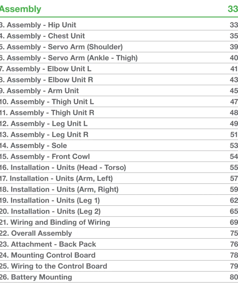
Assembly 33
3. Assembly - Hip Unit 33
4. Assembly - Chest Unit 35
5. Assembly - Servo Arm (Shoulder) 39
6. Assembly - Servo Arm (Ankle - Thigh) 40
7. Assembly - Elbow Unit L 41
8. Assembly - Elbow Unit R 43
9. Assembly - Arm Unit 45
10. Assembly - Thigh Unit L 47
11. Assembly - Thigh Unit R 48
12. Assembly - Leg Unit L 49
13. Assembly - Leg Unit R 51
14. Assembly - Sole 53
15. Assembly - Front Cowl 54
16. Installation - Units (Head - Torso) 55
17. Installation - Units (Arm, Left) 57
18. Installation - Units (Arm, Right) 59
19. Installation - Units (Leg 1) 62
20. Installation - Units (Leg 2) 65
21. Wiring and Binding of Wiring 69
22. Overall Assembly 75
23. Attachment - Back Pack 76
24. Mounting Control Board 78
25. Wiring to the Control Board 79
26. Battery Mounting 80
Table of Contents
Setting 81
Trim Position Conirmation 81
Setting the Home Position 84
Playing Sample Motions 89
Prior to Assembly
M3 Screw Hole
(depth: 8 mm)
Output Axis (upper axis) Upper case
Middle case Bottom case
Servo Case
Upper Side
Bottom Side
The rotational axis that outputs power inside servo. Used by securing parts such as servo h o r n a n d s e r vo a r m to the serration (notches surrounding the output axis).
Signal
Housing Bottom Axis
2.6 Screw Hole
(depth: 6 mm)
Case Screw
Screw for securing servo case. I s r e m o v e d o n c e d u r i n g assembly process, and used to secure frame and bracket.
Housing Guide
(marker to avoid inversion)
Free rotational axis that assists support of parts. Used by secur- ing parts such as free horn and bottom arm.
Serration
(seen from above)
+ (Vcc) - (GND)
Prior to Assembly
Servo Motor (KRS-2552HV) Parts Names
Prior to Assembly
Characteristics
In the present kit, this screw is mostly used for securing aluminum parts together. (The
"M" inscribed in the name of the screw indi- cates that it is a JIS standard metric screw.) This type of screw fits only in tapped hole. ( You can see indentations matching the screw inside the hole.) This type of screw can be used repeatedly unless it wears out or deforms.
Tightening Suggestions
Be careful not to break the screw head with a screwdriver. (Using a poorly fitting screwdriver with the wrong size, and over-tightening can destroy the screw head.)
Replace the screw with a new one when its head is destroyed, since it will become impossible to remove with a screwdriver. When the screw stops while tightening, check to make sure that the screw is not bent. Continued use of a bent screw can cause deformation of the tapped hole, and will become impossible to tighten even when using new screws.
Maintenance
Vibration causes screws to eventually loosen, even if the screws are tightened securely. Check regularly that the screws are not loosened even after assembly is completed. If you find that the screws loosen or fall off frequently with motion, screw locking adhesives (such as Loctite® and Screw-Lock) can be effective.
*When using locking adhesive, follow instructions attached to the adhesive.
Beware that securing screws with instantaneous adhesive can cause the screws to be perma- nently locked or the holes to be clogged.
Characteristic
This type of screw is used to secure plastic and some aluminum parts. The tapping screw thread is tapered and drill-shaped, and can secure parts by tapping threads into holes that have diameters smaller than the screw. (The action of cutting a spiral groove for the screw ridge to fit in a hole is called
“tapping”.) Because the screws are tapped into the parts, they can be fastened more tightly than normal screws (metric screws), but will require more force to tighten them in
Retightening a screw after re- moving it
If a tapping screw is removed after tighten- ing, grooves are already formed in the hole. T hu s, r e ti g hte ni n g s h o ul d b e d o n e a s follows:
(1) Position the screw vertically
Rotate the screw counter-clock-wise before tightening to make sure it is positioned verti- cally.
(2) Screw in without pushing
Screw
(coarse metric screw)
Tapping screw
Tighten while adding pressure. Right
When using several s c r e w s t o s e c u r e p a r t s , f i r s t t i g h t e n each screw lightly, and t h e n t i g h t e n t h e m further to secure the parts evenly with equal force.
Further, when using more than four screws to secure parts avoid adding uneven pressure to the parts by alter- nately tightening screws that are diagonally aligned.
(Example or tightening order) 1
2
3 4
Tighten lightly
Tighten further Right
Tightening Instructions
(1) Confirmation of screw holes
Before tightening tapping screws, always check to see if their positions and shapes are as shown in this Instruction.
* If tapping screws are screwed into normal screw holes or holes of ill-fitted sizes, the screw holes can deform, making it impos- sible to screw in the correct ones.
(2) Tapping
Tighten the tapping screw by pushing its head with a screwdriver so that the screw
Types of screws and how to handle them
Prior to Assembly
Can be expanded from 17 axis to 22 axis using five KHR-3HV expansion sets.
For the assembly of this kit, each ser vo with attached IDs are used as shown in the following layout figure.
* This is a frontal view.
For attaching the channel number, refer to the “Process of Assembly” section or the “List of Channels” shown below.
SIO1
SIO
1
How to secure servo cable decals
Cutting the decal with a cutter or scis- sors beforehand makes it easier to handle.
Cut decal as you like with reference to the left drawing.
Servo and channel identiication
List of IDs for KHR-3HV
Preparation
Preparation
1. Charging The Battery
Battery should be charged beforehand. See p 5-8 for charging methods.
In this kit, HV battery (Nickel-metal hydride battery) is used as a power source for operation. Charging typically takes about an hour and a half. The following sections refer to processes that use battery. While the battery is charging, install the exclusive “HeartToHeart4” software and the serial USB adapter HS driver, as well as reading all the instructions. Further, process 4 (Assembly of Chest Unit) and the subsequent 16 processes can be done in advance under your own judgment and responsibility.
* Be attentive and prepared for any abnormalities while charging the battery.
** Stop all use immediately if abnormal heat or an odd odor is noticed.
Preparation
2. Setting Servo Origins
Securing parts to servo output axis and precautions
good example 悪い例
good example
Mounting Small Diameter Horn
Mounting the Servo Arm
Origin Setting is an important pro- cess that decides the reference point of the servo rotation angle. Accurate origin setting will result in high reproducibility of sample mo- tions.
There is only one mounting direction for the servo arm, so if it does not exactly match the figure, shift it slightly to either the right or lef t. For instance, when setting the origin of servos in both shoul- ders, the more offset there is between the left and right shoulder servo origins, the more uneven the arms of the robot will be. Try to assemble by carefully finding the best positions.
Preparation
Assembly - Control Unit
• Required Parts
RCB-4HV --- 1 PCB base B --- 1 2-5 Low head tapping screw --- 2 Power switch harness --- 1
Completed Process Image
Icon Descriptions Points Tips Damage Warning Confirm
OFF
Power Supply Switch Harness RCB-4HV
PCB base B 2-5 Low Head
Tapping Screw
Temporarily Secure RCB-4HV to PCB base B using two 2-5 Low Head Tapping Screws.
* The screws will be taken off in a later process. The 2-5 Low Head Tapping Screws should be screwed on tem- porarily.
Connect the Power Source Switch Harness to the RCB- 4HV power terminal.
The power switch on the Power Source Switch Harness must be turned OFF at all times unless directed otherwise. If the switch is turned ON, the robot may unexpectedly move and fall off, break, or cause injury when connected to a power source.
DANGER
The connector is shaped so as to avoid reverse connection. Do not force the plug in incorrectly, as this may result in the connector breaking.
Preparation
Setting Servo Origins
Servo-motor KRS-2552HV used in this product has a maximum operation angle of approximately 270 degrees. Like human joints, it does not turn limitlessly and is restricted in its angle of motion. For the robot to operate properly, it must be assembled taking into consideration its mechanical restrictions and actual operation. Setting the origin of the servos is important in this respect.
If the origin is not correct, it might not operate properly when performing sample motions. Therefore, please understand the origin setting method and proceed carefully.
The origin must be set each time a servo arm is mounted on a servo.
Whenever origin setting is called for, the following process must be performed.
1. Things to prepare
Control Board RCB-4HV mounted on PCB base B in the preceding process is used.
The “HV battery 9N-800mAh” is used as the power source for RCB-4HV. Please charge beforehand. See p4-6 for charging method.
Furthermore, the motion creation software “Hear tToHeart4” must be installed in a personal computer.
Connect the RCB-4HV to the personal computer using the attached Serial USB Adapter HS and the Serial Extension Cable. Drivers should be installed in advance.
tpre da BA US re lai S
AN AP NJ EI AD M
Control unit
HV battery 9N-800mAh
Serial USB adapter HS
Serial extension cable
• For detailed description on the use of RCB-4HV, software and Serial USB Adapter HS, see “HTH4 user’s manual”.
• The personal computer should run Microsoft Windows XP or Vista.
tpre da BA US ai l Sre
AN AP NJ EI AD M
Plug to the USB port of your computer after connecting Serial Extension Cable to serial USB adapter HS.
Preparation
2. Conirm COM port for Serial USB adapter HS.
Connect serial USB adapter HS to the USB port on your computer.
* When connecting for the irst time, “Add New Hardware Wizard” runs. Complete the setup according to the KONDO USB Driver Installation Manual.
When installation of the driver for Serial USB adapter HS is completed, conirm the “COM Port Number”. This number is important when using the software, so write it down.
1. "Right click" on MY COMPUTER. 2. Select "Property".
* This description is based on Windows XP.
3. Click on the “Hardware” tab in the “System Property” window.
4. Click “Device Manager”
5. Click “+” for “Port (COM and LPT)” in Device Manager and check that SERIAL USB ADAPTER HS is dis- played. Confirm the COM number that appears in the ( ). * If SERIAL USB ADAPTER HS does not appear, either the driver is not installed properly or the Serial USB Adapter is not connected to the computer.
Preparation
3. Connection
1. Connect cable from Serial USB Adapter HS to COM terminal (port) of RCB-4HV.
2. Connect two ZH connection Cable B (ZHServo Connector) 450 mm to SIO1 and SIO5 of the SIO port.
SIO Port
(PIO Port)
* not used.
Power Supply Terminal
(Analog input port AD port)
* not used. COM Port
second pin from top
SIO1 SIO5
ZH Connection Cable B
(ZH/Servo Connector) 450 mm
* This side is the con- nector that is plugged to RCB-4.
*Plug so that the signal line (gray) faces the interior of the
circuit board. * Plug so that signal line
(white) faces the interior of the circuit board.
• Important Issues on Origin Setting
RCB-4 contains two systems of serial ports for servo driving: SIO1-4 and SIO5-8.
SIO1-SIO4 outputs the same signal and the servo motor operates the same way when connected to any of them. The same can be said for SIO5-SIO8.
In KHR-3HV, SIO1-SIO4 are used for the left side, and SIO5-SIO8 are used for the right side.
Therefore, servo motors with red and yellow ID decals are operated by connecting the cable from SIO1, and servo motors with blue and green ID decals are operated by connecting the cable from SIO5.
Left side of body / use SI01 cable
Right side of body / use SI05 cable
Preparation
4. Connecting cable to servo motor for origin setting
* Either of the connec- tion terminals on the servo motor can be used.
5 Activate the software
Activate the motion creating software “HeartToHeart4” and prepare for origin setting. If you have not inished installing ‘HeartToHeart4’, do so by using the CD-ROM provided.
* When irst activating the software ‘HeartToHeart4’, a ‘HeartToHeart4’ folder is created automatically in the My Documents folder on your computer. Project iles created must be saved in the “Projects” folder in the
‘HeartToHeart4’ folder.
ON
1. Switch ON the RCB-4 Power Switch.
When motion creation software ‘HeartToHeart4’ is activated, create a “Neutral Setting” project in the
‘HeartToHeart4’ folder.
2. Click “File” > “New Document” > “Project”
3. In the New Project window, name the new project
“Neutral Setting” .
* New projects may be given arbitrary names. Do not change the location for saving files unless necessar y. Files are normally saved in the
‘HeartToHeart4’ folder in “My Documents” .
Preparation
5. Select “Neutral Setting” in “Projects” in the ‘HeartToHeart4’ folder created in “Program Files” .
* Unless changed af ter installation of sof tware, the
‘HeartToHeart4’ folder is under “C:\Program Files” .
* When ‘HeartToHeart4’ software is installed, Sample Proj- ects are saved in the “Program Files” folder. The project for Neutral Setting is inside this Sample Project, so the Neutral Setting Project must be loaded from the Sample Project according to the above instructions, and imported to the New Project as described above.
6. Go back to the New Project Window and Click OK.
7. Select the previously-checked communication port number (COM).
* Here, COM10 is selected as an example.
8. Select “Project Setting”
* An error message as shown in the right appears when communication problems occur for reasons such as robot not being switched ON, or communication port (COM) number not being selected.
When normal connection is made, the following window ap- pears.
Preparation
9. Set ICS communication speed to 115200.
10. When “RAM” button is clicked, the project standard values are sent to RCB-4 and the servo becomes oper- able.
13. When operation is confirmed, return position to “7500 (origin)” .
* Double clicking the value next to the slide bar auto- matically changes the value to “7500” .
14. Turn off RCB-4, plug in another servo that needs origin setting, and repeat steps 9-13.
The above are the process for origin setting. The origin should be set for all servos based on these steps. 11. Select the servo motor that needs to be adjusted in
“Servo Motor Initial Setting” .
In the following example, the origin for servo “ID 0” (red) connected to the SIO1 channel is set.
12. Press “Sync” button and check operation using the po- sition slide bar.
* Servo moves with slide bar
Preparation
15, When all the procedures are completed, turn off RCB-4 and close the “RCB4 Project Setup” window.
Assembly
Assembly
3. Assembly - Hip Unit
• Required Parts
Dummy Servo 2500A --- 3 Arm Supporter 2500A --- 3 YHR-005_Body Base --- 1 YHR-008_Offset Arm La --- 1 YHR-009_Offset Arm Ra --- 1 2-5 Low Head Tapping Screw ---- 32 3-6 Flat Head Screw --- 3
Completed Process Image
Icon Descriptions Points Tips Damage Warning Confirm
Mount Arm Suppor ter 2500A (1 each) to Dummy Servo 2500A using 2-5 Low Head Tapping Screws (4 each).
Connect the three units prepared in step (1) using four 2-5 Low Head Tapping Screws, as shown in the figure.
* Make sure the front and back sides are correct. 2-5 Low Head
Tapping Screw
Arm Supporter 2500A
Dummy Supporter 2500A
2-5 Low Head Tapping Screw
* Check front
and back direction. Prepare 3 sets of
the same unit.
Assembly
Mount the YHR-005_Body Base using four 2-5 Low Head Tapping Screws and one 3-6 Flat Head Screw as shown.
Using eight 2-5 Low Head Tapping Screws, mount t h e Y H R - 0 0 8 _O f f s e t A r m L a a n d t h e Y H R - 009_Offset Arm Ra as shown in the figure. Use two 3-6 Flat Head Screws to secure the center.
Use four 2-5 Low Head Tapping Screws to secure the back side of the unit assembled in step (2).
2-5 Low Head Tapping Screw
3-6 Flat Head Screw
2-5 Low Head Tapping Screw Offset Arm La
* Check the direction
Offset Arm Ra
* Check the direction
3-6 Flat Head Screw 2-5 Low Head
Tapping Screw
YHR-005 Body Base
Assembly
4. Assembly - Chest Unit
• Required Parts
Servo Motor KRS-2552 [ID 0]--- 1 Servo Motor KRS-2552 [ID 1] --- 2 YHR-001_Body Frame F --- 1 YHR-002_Body Frame B --- 1 YHR-003_Shoulder Frame L --- 1 YHR-004_Shoulder Frame R --- 1 Arm Supporter 2500A --- 2 Battery-Holding Sponge --- 1 2-5 Low Head Tapping Screw ---- 20 M2-4 Low Head Screw --- 8 ZH Connection Cable A 200 mm -- 2 ZH Connection Cable A 50 mm --- 1 ZH Connection Cable B 100 mm -- 2
Completed Process Image
Icon Descriptions Points Tips Damage Warning Confirm
Servo Case Screw
Arm Supporter 2500A
Connection Cable
(ZH Connection Cable A 200 mm)
2-5 Low Head Tapping Screw
Arm Supporter 2500A
Connection Cable
(ZH Connection Cable A 200 mm)
2-5 Low Head Tapping Screw
Take out the Servo Motors with [ID 0] (red), [ID 1] (red) a n d [ I D 1] ( b l u e), a n d re move all se r vo case screws (4 each).
Put Connection Cable (ZH Connection Cable A 200 mm) through the Arm Sup- porter, and secure the Arm Supporter 2500 A to the Servo Motors [ID 1] (red) and [ID1] (blue), using 2-5 Low Head Tapping Screws (4 each).
* The direction of the cables differs between the two servos. Check the ID numbers in the figure.
Assembly
DANGER
Do not tighten case screw too much
Shoulder Frame L Shoulder Frame R
Servo Case Screw Servo Case Screw
Frontal View Frontal View
Plug the Cable to the Connector
Shoulder Unit L Shoulder Unit R
Using the servo screw removed in step (1), mount the YHR-003_Shoulder Frame L to the Servo Motor [ID1] (red), and the YHR-004_Shoulder Frame R to the Servo Motor [ID1] (blue). Make sure the direc- tions of the frames are correct.
Backside View Backside View
YHR-004 Shoulder Frame R
* The Shoulder Frames have different shapes on the left and right. Identify them by carefully checking the posi- tion of the holes.
YHR-003 Shoulder Frame L
Assembly
Connect the Servo Motor [ID 0] (red) to [ID 1] (red) using the Connection Cable (ZH Connection Cable A 50 mm), then connect the Connection Cable (ZH Connection Cable B 100 mm) to [ID 0] (red).
* In this process, the length of the cables are important. Please check carefully.
Connect the Connection Cable (ZH Connection Cable B 100 mm) to [ID 1] (blue). Make sure the cables are positioned as shown in Figure [A].
Use four 2-5 Low Head Tapping Screws on the servo output axis side and the four servo case screws taken off in step (1) on the bottom side.
* Cables are strung
as shown in the left figure Connection Cable (ZH Connection Cable A 200 mm)
Connection Cable (ZH Connection Cable A 200 mm) Connection Cable
(ZH Connection Cable B 100 mm)
Connection Cable (ZH Connection Cable A 50 mm)
Connection Cable (ZH Connection Cable B 100 mm)
* Stick a decal for the servo lead on Z H C o n n e c t i o n Cable B 100 mm.
2-5 Low Head Tapping Screw
Servo Case Screw
[A]
Assembly
Stick one Battery Holding Sponge to YHR-002_Body Frame B.
Using four 2-5 Low Head Tapping Screws and four M2-4 Low Head Screws, mount the YHR-002_Body Frame B with Sponge attached, to the unit assembled in step (6). Make sure the cables are positioned as shown in Figure [B]
Mount the YHR-001_Body Frame F using four 2-5 Low Head Tapping Screws and four M2-4 Low Head Screws.
Body Frame B
* Stick on to match the screw holes. Battery-Holding
Sponge
Body Frame B
2-5 Low Head Tapping Screw
M2-4 Low Head Screw 2-5 Low Head
Tapping Screw
[B]
* Make sure the cables are
positioned as shown in the figure.
2-5 Low Head Tapping Screw
M2-4 Low Head Screw 2-5 Low Head Tapping Screw
Body Frame F
Assembly
5. Assembly - Servo Arm (Shoulder)
• Required Parts
Joint Base 2500A --- 2 Bottom Arm 2500A --- 2 Small Diameter Horn --- 2 2.6-10BH Tapping Screw --- 2
M2-6BH Screw --- 8 Completed Process Image
Icon Descriptions Points Tips Damage Warning Confirm
Shoulder Servo Arm (left)
Shoulder Servo Arm (right) M2-6BH
screw Small Diameter
Horn Insert the Bottom Arm 2500A into the Joint
Base 2500A.
* Check the direction (front / back) of the Joint Base.
Secure the connecting parts using one 2.6- 10BH Tapping Screw each.
Mount the Small Diameter Horn as indi- cated in the figure and secure using four M2-6BH screws.
Bottom Arm 2500A
Joint Base 2500 A
Check the
front and back Prepare two sets of the same unit.
2.6-10BH Tapping Screw Prepare two sets
of the same unit.
*check
the front and back
Assembly
6. Assembly - Servo Arm (Ankle - Thigh)
• Required Parts
Joint Base 2500A --- 4 Bottom Arm 2500A --- 4 2.6-10BH Tapping Screw --- 2
Completed Process Image
Icon Descriptions Points Tips Damage Warning Confirm
Insert the Bottom Arm 2500A into the Joint Base 2500A.
* Check the direction (front / back) of the Joint Base.
Secure the connecting parts using one 2.6- 10BH Tapping Screw.
Bottom Arm 2500A
Joint Base 2500 A
Check the front and back
Prepare four sets of the same unit.
2.6-10BH Tapping Screw Prepare four sets
of the same unit.
Assembly
7. Assembly - Elbow Unit L
• Required Parts
Servo Motor KRS-2552 [ID2] --- 1 Servo Motor KRS-2552 [ID 4] --- 1 YHR-006_Servo Bracket A --- 1 YHR-007_Elbow Joint A --- 1 Dummy Servo 2500A --- 1 Arm Supporter 2500A --- 1 2-5 Low Head Tapping Screw ---16 3-6 Flat Head Screw --- 1
Completed Process Image
Icon Descriptions Points Tips Damage Warning Confirm
Dummy Servo 2500A
2-5 Low Head Tapping Screw Arm Supporter
2500A
2-5 Low Head Tapping Screw
3-6 Flat Head Screw YHR-006_Servo Bracket A
Elbow Joint A
2-5 Low Head Tapping Screw
Mount the Arm Supporter 2500A on the Dummy Servo 2500A using four 2-5 Low Head Tapping Screws.
Mount the YHR-006_Servo Bracket A using four 2-5 Low Head Tapping Screws and one 3-6 Flat Head Screw.
Mount the YHR-007_Elbow Joint A using four 2-5 Low Head Tapping Screws.
* Elbow Joints can be mounted on the top or bottom. Check the following figure carefully and mount accordingly.
YHR-006_
Servo Bracket A Elbow Joint A
M a k e s u r e there is space at the bottom.
Side View
Assembly
Servo Case Screw
Servo Case Screw
2-5 Low Head Tapping Screw
Servo Case Screw
2-5 Low Head Tapping Screw
Servo Case Screw Unscrew the two case screws on the bottom
from the Servo Motor [ID 2] (red).
Mount the Servo Motor [ID2] (red) to the unit prepared in step (3). Use two 2-5 Low Head Tapping Screws on the servo output axis side, and the two servo case screws taken off in step (4) on the bottom side.
Take two of the case screws on the right side (viewed from the bottom side) of Servo Motor [ID 4] (red).
Mount the Servo Motor [ID 4] (red) on the parts prepared in step 5. Use two 2-5 Low Head Tapping Screws on the servo output axis side, and two servo case screws taken off in step (6) on the bottom side.
DANGER
Be careful not to tighten the case screws too hard.
* Check the direction carefully when mounting the Servo Motor.
Assembly
8. Assembly - Elbow Unit R
• Required Parts
Servo Motor KRS-2552 [ID2] --- 1 Servo Motor KRS-2552 [ID 4] --- 1 YHR-006_Servo Bracket A --- 1 YHR-007_Elbow joint A --- 1 Dummy Servo 2500A --- 1 Arm Supporter 2500A --- 1 2-5 Low Head Tapping Screw ---16 3-6 Flat Head Screw --- 1
Completed Process Image
Icon Descriptions Points Tips Damage Warning Confirm
Dummy Servo 2500A
2-5 Low Head Tapping Screw Arm Supporter
2500A
2-5 Low Head Tapping Screw
3-6 Flat Head Screw YHR-006_Servo Bracket A
Elbow Joint A
2-5 Low Head Tapping Screw
Mount the Arm Supporter 2500A on the Dummy Servo 2500A using four 2-5 Low Head Tapping Screws.
Mount the YHR-006_Servo Bracket A using four 2-5 Low Head Tapping Screws and one 3-6 Flat Head Screw.
Mount the YHR-007_Elbow Joint using four 2-5 low head tapping screws.
* Elbow Joints can be mounted on the top or bottom. Check the following figure carefully and mount accordingly.
YHR-006_
Servo Bracket A Elbow Joint A
M a k e s u r e there is space at the bottom.
Side View
Assembly
Servo Case Screw
Servo Case Screw
2-5 Low Head Tapping Screw
Servo Case Screw
2-5 Low Head Tapping Screw Servo Case
Screw Unscrew the two case screws on the bottom from the Servo Motor [ID 2] (blue).
Mount the Servo Motor [ID 2] (blue) to the parts prepared in step (3). Use two 2-5 Low Head Tapping Screws on the servo output axis side, and two servo case screws taken off in step (4) on the bottom side.
Take two of the case screws on the left side (viewed from the bottom side) of Servo Motor [ID 4] (blue) .
Mount the Servo Motor [ID 4] (blue) on the parts prepared in step (5). Use two 2-5 Low Head Tapping Screws on the servo output axis side, and two servo case screws taken off in step (6) on the bottom side.
DANGER
Be careful not to tighten case screw too hard.
* Check the orientaton carefully when mounting the Servo Motor.
Assembly
9. Assembly - Arm Unit
• Required Parts
Hand Base B --- 2 Dummy Servo 2500A --- 2 Joint Base 2500A --- 2 Bottom Arm 2500A --- 2 Joint Base 2500A --- 2 Bottom Arm 2500A --- 2 2-8 Low Head Tapping Screw ---- 20 2.6-10BH Tapping Screw --- 2 Knuckle B --- 2 Thumb B --- 2
Completed Process Image
Icon Descriptions Points Tips Damage Warning Confirm
Prepare two sets of the same. Check the
front and back
Bottom Arm 2500A
Joint Base 2500A
2.6-10BH Tapping Screw
2-8 Low Head Tapping Screw
Dummy Servo 2500A As in the previous process “Assembly -
Shoulder Servo Arm”, insert the Bottom Arm 2500A to the Joint Base 2500A.
* Make sure to check the direction (front / back) of the Joint Base.
Secure the Arm's connecting parts using one 2.6-10BH Tapping Screw.
Mount the Dummy Servo 2500A as shown in the figure and secure using four 2-8 Low Head Tapping Screws. Make sure that the horn on the Dummy Servo 2500A is on the same side as the Bottom Arm 2500A.
Assembly
2-8 Low Head Tapping Screw
Hand Base B
Knuckle B
Thumb B
2-8 Low Head Tapping Screw
Knuckle B
Thumb B
2-8 Low Head Tapping Screw
Arm Unit L
Arm Unit R Mount the Hand Base B using four 2-8 Low Head Tapping Screws.
Insert the Knuckle B and the Thumb B into the Hand Base B and secure using two 2-8 Low Head Tapping Screws.
* Take precaution as the orientation of Thumb B differs be- tween the left and right arms.
Prepare two sets of the same.