1
C
O
N
T
EN
T
S
CONTENTS
RELEVANT MANUALS . . . .3
CHAPTER 1 INTRODUCTION
4
1.1
Database Overview . . . 4
1.2
MES Interface Module Overview . . . 6
MES interface basic system configuration. . . 7
CHAPTER 2 EXAMPLE SYSTEM OUTLINE
8
CHAPTER 3 REQUIRED EQUIPMENT FOR START-UP
10
CHAPTER 4 EQUIPMENT SETUP
12
CHAPTER 5 SOFTWARE INSTALLATION
15
5.1
Installation . . . 15
MX MESInterface installation procedure . . . 15
MX MESInterface installation . . . 16
CHAPTER 6 CREATING A DATABASE TABLE
19
6.1
OrderTable Creation . . . 19
6.2
History Creation. . . 21
CHAPTER 7 ODBC SETTING
23
CHAPTER 8 MES INTERFACE FUNCTION CONFIGURATION
25
8.1
General Description . . . 25
8.2
Specifying Parameters . . . 25
8.3
Operational Check. . . 35
Writing parameters to QJ71MES96 module . . . 35
Checking data written into DB table . . . 36
CHAPTER 9 FAQs
38
9.1
Troubleshooting by Symptom . . . 38
When using MES Interface Function Configuration Tool . . . 38
When using DB Connection Service Setting Tool . . . 42
When operating the MES interface module. . . 43
CHAPTER 10 CONCISE ERROR CODE LIST
49
10.1
Viewing MES Interface Module Error Codes . . . 49
10.2
Viewing Server Personal Computer Error Codes . . . 50
Log format . . . 50
Access log . . . 52
SQL failure log. . . 56
10.3
Error Code List . . . 57
Error codes for the MES interface module . . . 57
Error codes of DB Connection Service . . . 65
2
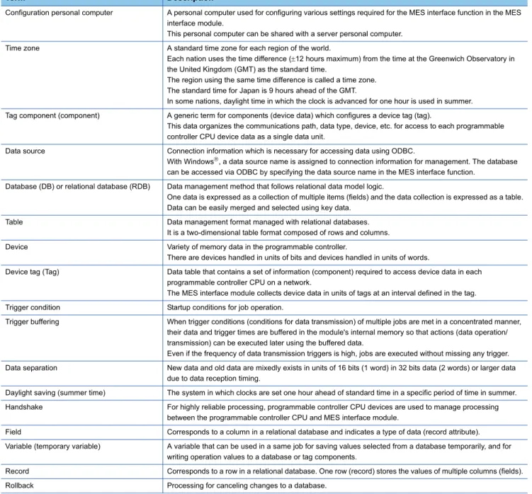
CHAPTER 11 TERMS
73
11.1
Definitions and Descriptions of Terms . . . 73
INDEX
75
REVISIONS . . . .77
TRADEMARKS . . . .78
Precautions before use . . . .78
3
RELEVANT MANUALS
The following manuals are also related to this product.
If necessary, order them by quoting the details in the list below.
Manual name [manual number] Description Available form
MES Interface Module User's Manual [SH-080644ENG]
Explains the functions, MES Interface Function Configuration Tool, DB Connection Service, parameter settings, troubleshooting, input/output, and buffer memory of MES interface module.
Print book PDF
GX Works2 Version 1 Operating Manual (Common) [SH-080779ENG]
Explains the system configuration of GX Works2 and the functions common to Simple project and Structured project such as parameter setting, operation method for the online function.
4
1 INTRODUCTION1.1 Database Overview1
INTRODUCTION
The MES interface enables simple, highly reliable data connectivity between automated machinery and manufacturing-related
computing applications, such as Manufacturing Execution Systems (MES) and Production Control Systems (PCS). These
applications depend on correct data collection and timely delivery. Compared to conventional connectivity implemented using
gateway computers, direct database connectivity implemented using the MES interface will decrease system complexity,
improve reliability and eliminate data loss, resulting in better agility, less maintenance and reduces total cost of ownership
(TCO).
This guide aims to provide an introductory guide to setting up the MES interface module. The guide is broken down into an
example system, setup, and maintenance sections. For further reading, please refer to the associated users and hardware
manuals provided by Mitsubishi Electric.
1.1
Database Overview
This section explains the databases that the MES interface uses as a source or destination for information exchanged with
programmable controller CPUs.
For this example, a database is defined as software which provides a virtual filing system for storing groups of related data. It
also provides a set of commands that enable access, editing and manipulation of the stored data.
The following are some examples of practical functions that may occur in a database.
• During processing of a set of data items, an error occurs.
In response, the user might apply a rollback command that
restores the data to its original state.
• While certain stored data items are being retrieved in one process, new data arrive that need to be stored in a second
process.
The database should handle completion of both actions without conflict or user intervention.
• A researcher desires to retrieve a specific set of 15 data items that was originally stored in the database on July 15th at
2:30 AM 5 years ago.
The user will create a "query" or command structure that the database understands as a request for
data retrieval. The database will return the specified information when the query is executed.
Database type
There are various database types including relational, hierarchical, and XML. The MES interface operates with relational
databases provided by Microsoft
or Oracle
.
Relational databases organize data into tables consisting of fields (columns) and records (rows). The contents in one
database can range from one table to many thousands.
M7000 J581-583
EH10 DHC8
300 120 500 500 30 30 10 0 Field
Record Production plan Production actual
1 INTRODUCTION
1.1 Database Overview
5
1
Database commands
All common databases implement a standardized command format called SQL (Structured Query Language). SQL defines
each command action a user can apply to operate the various database functions and the syntax for the command and
response messages paragraph change.
The MES interface module executes some of these commands. When acquiring data stored in a record, inserting data in a
new record, or writing modified data in an existing record, use Select command, Insert command, or Update command,
respectively.
Of many SQL commands available, these three cover direct data exchange between programmable controller CPUs and
databases. Creation of tables, deletion of records and all other database operations must be implemented outside the MES
interface.
■
Adding new records and updating table information
1.
Add a new record to the table that has fields for part number, production plan, and production actual.
(Insert command is executed via the production scheduling software.)
2.
After execution, add the production actual count to the record. (Update command is executed by the MES interface and
the production actual is moved from the programmable controller CPU to the database.)
M7000 J581-583
300 120 500 500 Part number Production plan Production actual Initial table structure
M7000 J581-583
300 120 500 500
M7000 J581-583
EH10
300 120 500 500 30 0 Part number Production plan Production actual Part number Production plan Production actual
Insert
M7000 J581-583
EH10
300 120 500 500 30 0
M7000 J581-583
EH10
300 120 500 500 30 12 Part number Production plan Production actual Part number Production plan Production actual
Update
6
1 INTRODUCTION1.2 MES Interface Module Overview1.2
MES Interface Module Overview
The MES interface provides a highly reliable and easy to implement method for exchanging data between programmable
controller CPUs or GOTs and common industrial quality databases. Most Manufacturing Execution Software Applications use
a database to source data and deposit results. The product is named 'MES interface', because it greatly improves MES
implementation and operation by providing a high quality, high function link to the factory equipment.
Setup of the MES functions is made using PC-based configuration software. For most applications, no computer language
programming or control logic programming is required. The person making setup need not know SQL language or XML
language, because setup is made in a menu driven format and deeper technical aspects are handled automatically. The idea
is that standard engineering staff can easily handle initial setup and subsequent modification of the MES interface
configuration.
Setup procedure
The general setup procedure is simple.
1.
Associate (map) device data of the programmable controller CPU to the appropriate fields or records in the database
table(s)
2.
Set trigger conditions under which data are to be collected and transferred
3.
Build transactions associating triggers with the specific data and action
1 INTRODUCTION
1.2 MES Interface Module Overview
7
1
MES interface basic system configuration
The overall system configuration when using the MES interface module is shown below.
*1 The server personal computer, SNTP server personal computer, and configuration personal computer can share one personal computer.
*2 Functions provided by MX MESInterface
*3 Since this guide mentions the default setting only, the setting for DB Connection Service is not explained. *4 MES interface module time is required when SNTP server personal computer time is used.
*5 It is not used in the example of system configuration in this guide.
System configuration Network connection
(1)*1 Server personal computer SNTP server personal computer*4*5
(a)*2*3 DB Connection Service
DB Connection Service Setting Tool
Ethernet
(b) Oracle
Microsoft SQL Server Microsoft Access and others
(2) MES interface module (c) CompactFlash card (required) Ethernet (3)*1 Configuration personal computer (d)*2 MES Interface Function Configuration Tool Ethernet
(4)*5 Access target CPU (e) RCPU, QCPU, QnACPU, and ACPU Supported networks
Ethernet
CC-Link IE ...
Data Base (1)
(a), (b)
(2)
(c)
(3)
(d)
(4)
8
2 EXAMPLE SYSTEM OUTLINE2
EXAMPLE SYSTEM OUTLINE
This section explains the process of building a simple data collection system using MES interface module.
A metal parts manufacturing line automated by the programmable controller CPU and the MES interface module is used as an
example.
Interactions between the control system and the production database are as follows:
1.
Acquiring the manufacturing schedule information (Database
MES interface module
Programmable controller CPU)
MES interface module acquires the target manufacturing number and lot ID codes from the table of the production control
database before starting the manufacture. The parts are manufactured according to the target manufacturing number.
The lot ID code is imprinted in front of the serial number on each part.
2.
Delivering the actual manufacturing information (Programmable controller CPU
MES interface module
Database)
After each part exits the inspection station, the actual serial number, production time and part weight are collected by MES
interface module and transferred to the production control database.
3.
Modifying data to improve usability (scaling in MES interface module)
The inspection scale notifies the control system of the part weight in grams (g) in positive numbers (decimal). However, a
production report from the database information should be read in kilograms. Therefore, the weight data is converted to
kilograms (kg) with MES interface module to prevent control logic changes and extra processing at the database-level.
Process Description
A Machining Machines metal materials and manufactures finished parts.
B Imprint Imprints a lot ID code and a specific serial number on each manufactured part. C Inspection Measures the weight of each completed parts.
(a) Control system (CPU module, MES interface module) (b) Production control database
(c) Target manufacturing number 35 units, lot ID code (US) (d) Acquisition of manufacturing schedule information (e) Delivering the actual manufacturing information
A B C
DB US2001 10:00:00 0.501kg
US2002 10:00:10 0.495kg US2035 10:05:50 0.512kg
(b) (c)
(a)
2 EXAMPLE SYSTEM OUTLINE
9
10
3 REQUIRED EQUIPMENT FOR START-UP3
REQUIRED EQUIPMENT FOR START-UP
Before creating a sample system, the following items must be prepared.
MES interface module QJ71MES96
The MES interface module provides linkage between device data of a programmable controller (production equipment) and a database of an information system (Manufacturing Execution Systems) without using a communication gateway.
CompactFlash card GT05-MEM-128MC
The MES interface module is equipped with and uses one CompactFlash card. For more on usable CompactFlash cards, please refer to the following manual.
MES Interface Module User's Manual Configuration software, MX MESInterface
SW1DNC-MESIF-E
Only specifying necessary data allows data communications (SQL texts) without any programming. This software includes the following tools:
• MES Interface Function Configuration Tool
Software that is run on a configuration personal computer and performs settings required for the MES interface function of the MES interface module. In addition to the settings, checking the operating status or working logs and stopping/restarting the MES interface function operation are also available with this software.
• DB Connection Service
Software that is run on a server personal computer and is used for linking a database to the MES interface module.
• DB Connection Service Setting Tool
Software that is run on a server personal computer and is used to change the settings of "DB Connection Service".
Personal computer The personal computer is used as a server personal computer and a configuration personal computer. In this guide, Microsoft Windows 7 Professional Operating System is used as the operating system (OS) in explanations.
For hardware requirements of the personal computer to be used, refer to the following manual.
MES Interface Module User's Manual
Twisted pair cables and a hub Used to connect the personal computer to the MES interface module, QJ71MES96. • Cables must be compliant with the standard of IEEE802.3 10BASE-T/100BASE-TX. • Use straight cables when using a hub, or use a crossover cable when not using a hub. Microsoft Access 2010 (32-bit) Relational database that is run on a server personal computer.
It is used to create a sample database.
For the applicable relational databases, refer to the following manual.
MES Interface Module User's Manual
Programmable controller CPU A programmable controller CPU system that uses the MES interface module.
For applicable CPU modules, number of modules, and base units, refer to the following manual.
MES Interface Module User's Manual
GX Works2 An integrated programming tool for performing design, debugging, and maintenance of sequence programs for programmable controller CPUs. By using this, sequence program monitoring, program or data modification during program execution, and ON/OFF of inputs/outputs are also available. For the operation method, refer to the following manual.
3 REQUIRED EQUIPMENT FOR START-UP
11
12
4 EQUIPMENT SETUP4
EQUIPMENT SETUP
Components required to build a sample system are shown below:
Connection method
■
Direct connection
The following shows when connecting a MES interface module to a personal computer directly.
■
Connection via a hub
The following shows when connecting a MES interface module to a personal computer via a hub.
(1) MES interface module (IP: 192.168.3.3) (2) Ethernet (twisted pair cable (crossover cable)) (3) Personal computer (IP: 192.168.3.1)
(1) MES interface module (IP: 192.168.3.3) (2) Ethernet (twisted pair cable (straight cable)) (3) Personal computer (IP: 192.168.3.1) (4) Hub
(1)
(2)
(3)
(2)
4 EQUIPMENT SETUP
13
4
Setup procedures
1.
Personal computer
• Install Microsoft
Access 2010 (32-bit) on the personal computer.
• Set the IP address of a personal computer to '192.168.3.1'.
This setting can be configured on the "Internet Protocol (TCP/IP) Properties" screen.
2.
MES interface module (QJ71MES96)
• Mount the MES interface module on a slot other than the CPU slot on the base unit.
• Insert the CompactFlash card in the MES interface module CompactFlash card slot.
• The CompactFlash card is formatted using the format function of the MES Interface Function Configuration Tool.
14
4 EQUIPMENT SETUP3.
Programmable controller CPU
5 SOFTWARE INSTALLATION
5.1 Installation
15
5
5
SOFTWARE INSTALLATION
This section explains how to install MX MESInterface function configuration software in each operating environment.
In this guide, the method when using Microsoft
Windows
7 Professional Operating System is explained. When using other
operating systems (OS), refer to the following manual.
MES Interface Module User's Manual
5.1
Installation
This section explains how to install MX MESInterface.
MX MESInterface installation procedure
If a confirmation message for overwriting DLL files is displayed at installation, click the [Yes] button and
overwrite the DLL files.
Not overwriting the DLLs may fail to execute MX MESInterface correctly.
Installation start
Execute setup.exe.
Select the component to be installed.
Which software is to be installed?
Enter user information.
Enter the product ID.
Select the installation destination.
Enter user information.
Enter the product ID.
Select the installation destination. DB Connection Service
and
DB Connection Service Setting Tool
MES Interface Function Configuration Tool
Installation
16
5 SOFTWARE INSTALLATION5.1 InstallationMX MESInterface installation
Note the following when installing MX MESInterface:
• When installing MX MESInterface, log on as a user with Administrator authority.
• Before installing MX MESInterface, close any other applications running on Windows
.
• Updates for the OS or software from other companies, such as Windows
Update or java update, automatically restart the
computer and in some cases, the installer will not operate normally. Install the software after changing the settings so that
updates do not automatically restart the computer.
1.
Start Windows Explorer, then click the drive in which the
CD-ROM is loaded.
Double-click "setup.exe". To display Windows Explorer,
right-click [Start], then select [Explorer].
2.
The dialog box for selecting the component to be
installed is displayed.
Select the component to be installed with the radio
button, then click the [Install] button.
• If the left message appears, click the [Cancel] button and after uninstalling MX MESInterface, install this product.
• If the left message appears, install this product on a computer to which the supported operating system (OS) is installed.
• If the left message appears, execute \EnvMEL\Setup.exe in the CD-ROM for this product.
5 SOFTWARE INSTALLATION
5.1 Installation
17
5
3.
The left screen appears. Check that all applications
have been closed, then click the [OK] button.
If any applications are running, close them all.
4.
Setup starts.
The left screen appears. Check the description, then
click the [Next] button.
5.
Enter a user name and company name, then click the
[Next] button.
6.
Check the user name and company name registered.
18
5 SOFTWARE INSTALLATION5.1 InstallationAfter installing MES Interface Function Configuration Tool and DB Connection Service Setting Tool, the icons
are registered in the start menu.
7.
Register the product ID.
Enter the product ID, then click the [Next] button. The
product ID is shown on the software registration card
included in the product.
8.
Specify the folder for installation destination.
When using the default folder, click the [Next] button. To
change the folder, click the [Browse] button, then
specify the drive and folder for installation destination.
Up to 100 characters including '\MESIF' can
be used for the installation destination.
9.
When the left screen appears, installation is complete.
Click the [OK] button.
10.
The dialog box for selecting the component to be
installed is displayed.
When installing the other software, select the
component to be installed with the radio button, then
click the [Install] button.
6 CREATING A DATABASE TABLE
6.1 OrderTable Creation
19
6
6
CREATING A DATABASE TABLE
Before setting the ODBC setting and MES interface function setting, create two types of database table in Microsoft
Access
2010.
6.1
OrderTable Creation
1.
Start [Microsoft Access 2010] from Windows
Start.
2.
Select "New" on the [File] tab and enter
'Sample_DB.accdb' in the "File Name", then click the
[Create] button.
In the operation example, the save location is 'C:\MES\'.
3.
Right-click "Table 1" in the [Tables] and select [Design
View] from the shortcut menu.
4.
Enter 'OrderTable' in the "Table Name" and click the
[OK] button.
5.
Set each setting item on the [OrderTable] tab and the
[General] tab according to the following table.
Field Name Data Type Field Size
OrderCode Number Integer
ProductCode Text 2
20
6 CREATING A DATABASE TABLE6.1 OrderTable Creation6.
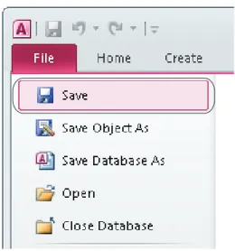
Select "Save" on the [File] tab.
7.
Right-click "OrderTable" in the [Tables] and select
[Open] from the shortcut menu.
8.
Set each setting item on the [OrderTable] tab according
to the following table.
OrderCode ProductCode PlanNumber
1 EN 20
2 US 35
6 CREATING A DATABASE TABLE
6.2 History Creation
21
6
6.2
History Creation
Create a table in the same way as OrderTable.
1.
Click "Table" on the [Create] tab.
2.
Right-click "Table 1" in the [Tables] and select [Design
View] from the shortcut menu.
3.
Enter 'History' in the "Table Name" and click the [OK]
button.
4.
Set each setting item on the [History] tab and the
[General] tab according to the following table.
Field Name Data Type Field Size
SerialCode Text 6
Date_Time Date/Time
22
6 CREATING A DATABASE TABLE6.2 History Creation5.
Select "Save" on the [File] tab and end the database
7 ODBC SETTING
23
7
7
ODBC SETTING
Set the ODBC setting before setting parameters with MES Interface Function Configuration Tool. This section explains the
setting method for the following operating system (OS) and relational databases.
• Operating system (OS): Microsoft
Windows
7 Professional Operating System
• Relational database: Microsoft
Access 2010 (32-bit)
When using other operating systems (OS) or relational databases, refer to the following manual.
MES Interface Module User's Manual
ODBC setting procedure
1.
Clicking [System and Security] on the Control Panel
displays the [System and Security] dialog box.
To display the Control Panel, select [Start]
[Control
Panel].
2.
Clicking [Administrative Tools] displays [Administrative
Tools] dialog box.
For use of a 64-bit version operating system,
type the following at the command prompt to
start the "ODBC Data Source Administrator".
%SystemRoot%\SysWOW64\odbcad32.exe
3.
Double clicking [Data Sources (ODBC)] displays [ODBC
24
7 ODBC SETTING4.
Select the [System DSN] tab, and click the [Add] button.
5.
Select "Microsoft Access Driver (*.mdb, *.accdb)" and
click the [Finish] button.
6.
Enter 'SAMPLE' in the "Data Source Name" and click
the [Select] button in the "Database".
Any data source name can be set.
The name set above is used for the data
source name in the "Server service settings".
7.
Select 'Sample_DB.accdb' in the "Database Name" and
click the [OK] button.
The database name is for accessing to
Access
database.
Specify a save destination for the created
database tables.
8.
Select "None" in the "System Database" and click the
[OK] button.
9.
Click the [OK] button on the "ODBC Data Source
8 MES INTERFACE FUNCTION CONFIGURATION
8.1 General Description
25
8
8
MES INTERFACE FUNCTION CONFIGURATION
8.1
General Description
This section explains the procedure for specifying parameters using the MES Interface Function Configuration Tool. Table
below lists the parameters to be specified.
• System setting
• Access target CPU settings
• Device tag settings
• Server service settings
• Job settings
8.2
Specifying Parameters
1.
Start the MES Interface Function Configuration Tool.
Select [MELSOFT]
*2
[MESInterface]
[MELSEC-Q series MES interface function configuration tool]
*3from
Windows
Start
*1.
*1 Select [All apps] on the Start screen or [Start] [All Programs].
*2 When the MX MESInterface (version 1.12N or earlier) is installed, select [MELSOFT Application].
*3 When the MX MESInterface (version 1.12N or earlier) is installed, [MES interface function configuration tool] is displayed.
2.
"System setting" and "Access target CPU settings" need not be established because they take default settings.
3.
Set the device tag setting.
26
8 MES INTERFACE FUNCTION CONFIGURATION8.2 Specifying Parameters4.
Enter 'GettingData' to "Device tag name", and specify parameters as shown below.
• Device tag name: GettingData
• Sampling settings: Normal sampling, 1 second
• Component setting input
5.
Specify another device tag setting.
Select "Device tag settings", and click the [Add] button.
Component name CPU name Device Data type Statistical
type
OCode ControlCPU D100 Single word
SCode ControlCPU D300-D302 String, 6 characters
Weight_g ControlCPU D400 Single word
8 MES INTERFACE FUNCTION CONFIGURATION
8.2 Specifying Parameters
27
8
6.
Enter 'PuttingData' to "Device tag name", and specify parameters as shown below.
• Device tag name: PuttingData
• Sampling settings: Do not sample
• Component setting input
7.
Set the server service setting.
Select "Server service settings", and click the [Add] button.
Component name CPU name Device Data type Statistical type
Plan ControlCPU D200 Single word
28
8 MES INTERFACE FUNCTION CONFIGURATION8.2 Specifying Parameters8.
Enter 'SampleServer' to "Server service name", and specify parameters as shown below.
9.
Set the job setting.
Select "Job settings", and click the [Add] button.
Setting item Setting description
Server service name SampleServer Server type Database server IP address 192.168.3.1 Port No. (1024 to 65535) 5112
User name
Password
Confirm password Data source name SAMPLE
8 MES INTERFACE FUNCTION CONFIGURATION
8.2 Specifying Parameters
29
8
10.
Enter 'GettingPlan' to "Job name", and specify trigger conditions as shown below.
11.
Next, specify an action.
Select "Communication action", and click the [Add] button.
Setting item Setting description
Job name GettingPlan
Enable at module startup Selected
Trigger buffering Unselected
30
8 MES INTERFACE FUNCTION CONFIGURATION8.2 Specifying Parameters12.
Select "Select" in the "Action type", and specify parameters for the communication action as shown below.
(Default setting is acceptable for the exception processing settings.)
An SQL text to send to the database is automatically created after setting parameters.
A created SQL text can be checked in "Generated SQL text" on the "Communication action" screen.
Configure the settings as follows:
• Action type: Select
• Table name: OrderTable
• DB-tag link settings
• Select/Update/Delete conditions
13.
Specify another job setting.
Select "Job settings", and click the [Add] button.
Field name Tag/Type Component
ProductCode PuttingData PCode
PlanNumber PuttingData Plan
Field name Condition Tag/Type Component
8 MES INTERFACE FUNCTION CONFIGURATION
8.2 Specifying Parameters
31
8
14.
Enter 'Reporting' to "Job name", and specify trigger conditions as shown below.
Set the trigger 1 as shown below.
15.
Next, specify an action.
Select "Operation action", and click the [Add] button.
Setting item Setting description
Job name Reporting Enable at module startup Selected Trigger buffering Selected
Trigger conditions Trigger 1: Value monitoring startup
Tag Component Conditio
n
Tag/Type Component
32
8 MES INTERFACE FUNCTION CONFIGURATION8.2 Specifying Parameters16.
Set the operation action as shown below.
17.
Specify another action.
Select "Communication action", and click the [Add] button.
Setting item Substitution tag
Component Operation tag Component Operator Operation tag Compon
ent
8 MES INTERFACE FUNCTION CONFIGURATION
8.2 Specifying Parameters
33
8
18.
Select "Insert" in the "Action type", and specify parameters for the communication action as shown below.
An SQL text to send to the database is automatically created after setting parameters.
A created SQL text can be checked in "Generated SQL text" on the "Communication action" screen.
• Action type: Insert
• Table name: History
• DB-tag link settings
19.
Upon the completion of the setting operation, save associated parameters.
Select [Project]
[Save As].
Field name Tag/Type Component
SerialCode GettingData SCode
Date_Time [Date] Module time
34
8 MES INTERFACE FUNCTION CONFIGURATION8.2 Specifying Parameters20.
Enter 'Sample_Config' to "File name", and save the project.
21.
Select [Online]
[Remote operation].
22.
When the "Transfer setup" screen appears, enter the IP address, user name, and password, then click the [OK] button.
Default settings are as follows:
23.
Select "Format" for "CompactFlash card operation", and click the [Execute] button to format the CompactFlash card.
When formatting the CompactFlash card, all the data is deleted.
Back up required data before formatting the CompactFlash card.
24.
Once formatting is complete, click the [Close] button and close the "Remote operation" screen. Turn the power of the
programmable controller CPU from OFF to ON and restart the MES interface module.
Setting item Setting description
IP address 192.168.3.3
User name QJ71MES96
8 MES INTERFACE FUNCTION CONFIGURATION
8.3 Operational Check
35
8
8.3
Operational Check
The following shows the writing procedure of parameters to the MES interface module and checking procedure of the writing
result to a DB table.
Writing parameters to QJ71MES96 module
1.
Select [Online]
[Write] to write parameter settings.
2.
When the "Transfer setup" screen appears, enter a user name and password, and click the [OK] button.
Default settings are as follows:
3.
After completing the writing, reset the programmable controller CPU and start the QJ71MES96 module.
After resetting the programmable controller CPU , turn the status to RUN.
4.
The parameters are written to the database automatically after starting the QJ71MES96 module .
Setting item Setting description
User name QJ71MES96
36
8 MES INTERFACE FUNCTION CONFIGURATION8.3 Operational CheckChecking data written into DB table
1.
Select "Open" in Microsoft
Access
2010 and open
the "Sample_DB.accdb" file
("C:\MES\Sample_DB.accdb").
2.
Right-click "History" in the [Tables] and select [Open]
8 MES INTERFACE FUNCTION CONFIGURATION
8.3 Operational Check
37
8
3.
The result (manufacturing information), which is
38
9 FAQs9.1 Troubleshooting by Symptom9
FAQs
9.1
Troubleshooting by Symptom
When using MES Interface Function Configuration Tool
This section explains troubleshooting information on the setting of MES Interface Function Configuration Tool.
Common to all settings
Symptom Checked item Corrective action
Unable to connect MES Interface Function Configuration Tool to the MES interface module.
Is there any disconnection in the connection route? • Connect the cables properly. Is the IP address setting correct? • Review the IP address setting.
Is the user name and password setting correct? • Review the user name and password setting. Is the IP address duplicated? • Review the IP address setting.
Is there a firewall and/or a proxy server in the connection route?
• Consult your network administrator about the firewall setting and/or the setting contents of the proxy server.
Is the MES interface module connected to the network?
(Network connection status (X4) = ON)
• Connect the MES interface module to the network.
Is it in "Online" mode? • Change the mode to "Online".
Is there any problem on the personal computer? • Replace it with another personal computer. MES Interface Function Configuration Tool does
not start.
Have five MES Interface Function Configuration Tools already started?
• Up to five MES Interface Function Configuration Tools can be started in a personal computer. • Terminate the other MES Interface Function
Configuration Tools and then start it. Is the memory or the system resources on the
personal computer sufficient?
• Increase the necessary memory on the personal computer.
• Close other programs and restart MES Interface Function Configuration Tool.
The screen of MES Interface Function Configuration Tool is not displayed correctly.
Is the memory or the system resources on the personal computer sufficient?
• Increase the necessary memory on the personal computer.
• Close other programs and restart MES Interface Function Configuration Tool.
Cannot operate MES Interface Function Configuration Tool.
Forced to terminate MES Interface Function Configuration Tool.
Unable to import a project file. The specified project file is incorrect or corrupted. • Specify a correct project file. Is there any inconsistency in the setting? • Review the setting and correct it if any. Did the number of settings exceed the upper limit? • Review the number of settings. Unable to import a CSV file. Is the CSV file description correct? • Review the CSV file description.
Is there any inconsistency in the setting? • Review the setting and correct it if any. Did the number of settings exceed the upper limit? • Review the number of settings. "Device tag name" is not displayed for the setting
item by which data are written to a tag.
Is the tag set to data-write-disabled? • Set the tag to data-write-enabled.
All the text is not displayed in a table. (The text display is truncated.)
Is the column to narrow? • Adjust the column width of the table.
The MESInterface folder in Start menu is not deleted behind the uninstallation.
9 FAQs
9.1 Troubleshooting by Symptom
39
9
System setting
Access target CPU settings
Device tag settings
Server service settings
Symptom Checked item Corrective action
A desired device tag name is not displayed in "DB buffering settings".
Is the tag set to data-write-disabled? • Set the tag to data-write-enabled.
Symptom Checked item Corrective action
Unable to change or delete an item in "Access target CPU settings".
Is it the first item? • Since the control CPU is set as the first item, deletion or setting change is not allowed for it. (Only the CPU name can be changed.) • If it is any item other than the first one, change
the item or add an item.
Is the selected item used in "Device tag settings"? • An item used for another item is unable to be deleted.
• As the error dialog box appears, identify the location, stop using it for another item, and then delete the item.
Symptom Checked item Corrective action
Unable to change or delete an item in "Device tag settings".
Is the selected item used in "Job settings"? • An item used for another item is unable to be deleted.
• As the error dialog box appears, identify the location, stop using it for another item, and then delete the item.
Is the selected item used in "DB buffering settings" of "System setting"?
Is the selected item used in "Access error notification setting" of "Server service settings"? Unable to set or change "Device tag name". Is the same name used for "Server service name"
or another "Device tag name"?
• Because a unique name must be used for "Server service name" and "Device tag name", use a different name.
Unable to select "High-speed sampling". Is "High-speed sampling" selected in another "Device tag settings"?
• Registration of "High-speed sampling" is limited to one tag only.
• Unselect "High-speed sampling" in "Device tag settings".
Is any other than the first item (Control CPU) in "Access target CPU settings" selected in "CPU name" in "Component setting input"?
• If "High-speed sampling" is selected, only the first item in "Access target CPU settings" (Control CPU) can be selected for the tag component.
• Delete the component setting with selection of any other than the first item, or change the setting so that the first item will be used for it. Is the number of device points set in the tag setting
more than 96?
• Reduce the number of device points in the tag setting to 96 or less.
• hen "High-speed sampling" is selected, set tag component devices within the total of 96 points. Unable to change the "Prohibit data writing"
setting.
Is the tag used for a setting item by which data are written to the tag?
• "Completion notification" of "Handshake operation", and substitution tags for "Select" on the "Communication action" screen
• If the tag is used for a setting item by which data are written to the tag, "Prohibit data writing" cannot be unselected.
• Stop using the tag for the setting item by which data are written to the tag, before changing the setting.
Symptom Checked item Corrective action
Unable to set or change "Server service name". Is the same name used for another "Server service name" or "Device tag name"?
• Because a unique name must be used for "Server service name" and "Device tag name", use a different name.
Unable to change "Server type". Is the "Server service name" same as the existing one?
• Review the server service name.
A desired device tag name is not displayed in "Access error notification setting".
40
9 FAQs9.1 Troubleshooting by SymptomJob settings
Online
Symptom Checked item Corrective action
Unable to set "DB buffering settings". Is there any Select action set for the job? • Do not use Select actions in the job where DB buffering is enabled.
• The DB buffering is not available for jobs performing Select actions.
Unable to set a new variable. Are there 64 variables that were already defined in the job?
• Delete any unnecessary variable settings of the job.
• Up to 64 variables can be set for one job. Unable to select "Trigger 2" in "Trigger conditions". Is "Handshake operation" selected for "Trigger 1"? • When "Handshake operation" is selected,
selection is not allowed for "Trigger 2". • Select any other than "Handshake operation" for
"Trigger 1". A desired device tag name is not displayed in
"Completion notification" of "Handshake operation".
Is the tag set to data-write-disabled? • Set the tag to data-write-enabled.
A desired device tag name for "Select" is not displayed in "DB-tag link settings" on the "Communication action" screen. A desired device tag name for "Exception processing" is not displayed on the "Communication action" screen.
A desired device tag name is not displayed in "Substitution tag" on the "Operation action" screen. A desired device tag name is not displayed under "Notify errors (job cancellation) that occur during job execution".
Unable to set the settings in "Exception processing" on the "Communication action" screen.
Is the DB buffering enabled? • Disable the DB buffering. Is "Insert", or "Stored procedure" set for "Action
type"?
• Set any other than "Insert" and "Stored procedure" for "Action type".
Symptom Checked item Corrective action
Unable to write a project to the MES interface module.
Is the total number of fields in the project more than 8192?
• Up to 8192 fields can be set within one project. • Delete any unnecessary field settings. Failed in online operation. Is the IP address set in [Online] [Transfer setup]
correct?
• Select [Online] [Transfer setup], and review the setting.
• Perform the online operation for the MES interface module selected from [Online] [Transfer setup].
Send a PING request from the configuration personal computer to the IP address of the MES interface module. Is there a response?
• If no response is returned, check if the module is powered up or if the network is properly connected.
Has the account set in [Online] [Transfer setup] been registered to the MES interface module?
• Select [Online] [Transfer setup], and review the setting.
• Specify the account that is registered in the MES interface module.
Is the firewall function of the operating system or security software enabled on the configuration personal computer?
• Check the firewall setting.
Unable to select [Online] [One-shot execution]. Was the job for one-shot execution selected? • Select the job for one-shot execution, and then select [Online] [One-shot execution]. Failed to perform [Online] [One-shot execution]. During one-shot execution, was the power of the
programmable controller turned OFF ON, or was the programmable controller CPU reset?
• Write a project again and perform "Update settings".
Has a communication error occurred during one-shot execution?
Is there any difference between the system settings being used on the MES interface module and the system settings of the MES Interface Function Configuration Tool?
9 FAQs
9.1 Troubleshooting by Symptom
41
9
Failed to format the CompactFlash card. Check for an error code in "System monitor" of GX Works2.
• By the error code, check the error details and take corrective actions.
• Format the CompactFlash card again. Is the MES interface module operation in the "Stop"
state?
• Stop the MES interface module operation, and then execute formatting.
It takes time to write the settings to the MES interface module.
Is the MES interface module operation in the "Stop" state?
• Stop the MES interface module operation, and then write the settings.
The latest table name, field name, or procedure name is not displayed in the list displayed by clicking the [Browse table name], [Browse field name], or [Browse procedure name] button on the "Communication action" screen.
Is the information of the database updated while opening the "Communication action" screen?
• Click the [Browse table name], [Browse field name], or [Browse procedure name] button on the "Communication action" screen again. • Change the database on the "Communication
action" screen, and click the [Browse table name] or [Browse procedure name] button again.
• Change the database and the table name on the "Communication action" screen, and click the [Browse field name] button again.
Is an inapplicable character used for the table name, field name, or stored procedure name?
• Change the table name, field name, or stored procedure name to the name which does not include an inapplicable character.
Does the table name or field name name exceed 32 characters?
• Change the table name or field name to a name which does not exceed 32 characters. Does the stored procedure name exceed 32
characters?
• Change the stored procedure name to a name which does not exceed 32 characters. Is there a stored procedure whose arguments are
more than 256?
• Change the arguments of the stored procedure to 256 or less.
Are a large number of tables, fields, or stored procedures registered to the database?
• Set the DB access time much longer.
The table name/field name/procedure name cannot be browsed properly when [Browse table name]/ [Browse field name]/[Browse procedure name] on the "Communication action" screen is executed.
Is there a response from the IP address of the server personal computer when a PING is sent from the configuration personal computer?
• If there is no response, check if the power of the server personal computer is ON, or the network connection status is correct.
Is a personal computer restarted after installing relational database?
• Restart the personal computer.
Is the port number set in "Service port" of DB Connection Service Setting Tool same as the one set in "Port No." in "Server service settings" of MES Interface Function Configuration Tool?
• Set the same value.
Is the firewall function of the operating system or security software enabled on the configuration personal computer or server personal computer?
• Check the firewall setting.
Is the port specified in "Service port" of DB Connection Service Setting Tool being used for the database or any other application?
• Change the port number to another that is not being used for the database or any other application.
Has any Check Point software been installed in the server personal computer?
• Uninstall the Check Point software.
Is the ODBC setting of the database correct? • Review the ODBC setting of the database. Is "Limit IP addresses permit to connect" of DB
Connection Service Setting Tool selected?
• If it is set, add the IP address of the configuration personal computer to "Permitted IP addresses list".
[Browse table name] or [Browse field name] button Is the version of DB Connection Service 1.09K or later?
• When the installed software version is 1.08J or earlier, update the software.
[Browse procedure name] button
Is the version of DB Connection Service 1.10L or later?
• When the installed software version is 1.09K or earlier, update the software.
Has the ODBC setting been changed after the table name, field name, or stored procedure name was successfully browsed?
• Restart MES Interface Function Configuration Tool, and then click the [Browse table name], [Browse field name], or [Browse procedure name] button.
Failed to acquire the return values and arguments when Stored procedure is selected on the "Stored procedure list" screen.
Is the information of the database updated while opening the "Communication action" screen?
• Change the database on the "Communication action" screen, and click the [Browse procedure name] button again.
42
9 FAQs9.1 Troubleshooting by SymptomWhen using DB Connection Service Setting Tool
This section explains troubleshooting information on the setting of DB Connection Service Setting Tool.
The elements cannot be added on the tag setting screen. (Device range is incorrect.)
Was the device of RCPU which does not exist in the range of QCPU or C Controller module specified?
• Specify the device number within the range that can be specified in QCPU or C Controller module.
Symptom Checked item Corrective action
Unable to start DB Connection Service Setting Tool.
Has another DB Connection Service Setting Tool been already started?
• Only one DB Connection Service Setting Tool can be activated.
• Terminate the already started DB Connection Service Setting Tool.
Is the memory or the system resources on the personal computer sufficient?
• Increase the necessary memory on the personal computer.
• Close other programs and restart DB Connection Service Setting Tool. Is not the tool being installed, without uninstalling? • Restart the personal computer. The screen of DB Connection Service Setting Tool
is not displayed correctly.
Is the memory or the system resources on the personal computer sufficient?
• Increase the necessary memory on the personal computer.
• Close other programs and restart DB Connection Service Setting Tool. Cannot operate DB Connection Service Setting
Tool.
Forced to terminate DB Connection Service Setting Tool.
Unable to reflect the setting. Was a user ID having the administrator authority used for the login?
• Log in again with a user ID having the administrator authority.
Is there no permitted IP address? • Clear the "Limit IP addresses permit to connect" checkbox, or add an IP address for which connection is permitted.
Unable to export a file. Is there no permitted IP address? • Clear the "Limit IP addresses permit to connect" checkbox, or add an IP address for which connection is permitted.
An access log output error is recorded in "Event Viewer" of "Administrative Tools" in Windows.
Is the file set in "Output destination" read-only? • Review the file specification. Is the access to the folder containing the file set in
"Output destination" authorized?
• Check the right of access to the folder.
Is the drive space of the server personal computer full?
• Check the free space on the drive.
An SQL failure log output error is recorded in "Event Viewer" of "Administrative Tools" in Windows.
Is the file set in "Output destination" read-only? • Review the file specification. Is the access to the folder containing the file set in
"Output destination" authorized?
• Check the right of access to the folder.
Is the drive space of the server personal computer full?
• Check the free space on the drive.
"The DBConnector service failed to start due to the following error: The system cannot find the file specified." is recorded in "Event Viewer" of "Administrative Tools" in Windows.
Does the following file exist in the installing destination directory of DB Connection Service and DB Connection Service Setting Tool?
"MESIF\DBConnector.exe"
• Uninstall DB Connection Service and DB Connection Service Setting Tool, and restart the personal computer before reinstallation.
Is the personal computer restarted after uninstalling DB Connection Service and DB Connection Service Setting Tool? Oracle's data source driver is not located although
"%SystemRoot%\SysWOW64\odbcad32.exe" was executed on 64-bit version Windows.
Has the 32-bit version of Oracle Client been installed?
• Install the 32-bit version of Oracle Client, and then execute
"%SystemRoot%\SysWOW64\odbcad32.exe" again.
The "MESInterface" folder in Start menu is not deleted behind the uninstallation.
Is the "MESInterface" folder empty? • Delete the "MESInterface" folder manually.
9 FAQs
9.1 Troubleshooting by Symptom
43
9
When operating the MES interface module
This section shows the troubleshooting of problems that may arise during operation of the MES interface module.
Troubleshooting about LED indication and I/O signals
Troubleshooting about network connection
Troubleshooting about communication with access target CPUs
Symptom Checked item Corrective action
The RUN LED does not turn on. Is the module in preparation? • Wait for startup of the module.
Is the Watchdog timer error (X1F) ON? • If a watchdog timer error is identified, please consult your local Mitsubishi representative. The ERR. LED is on or flashing. Is the battery connected? Or, has the battery
voltage dropped?
• Check the battery connection. • Replace the battery. Is any of the error detection signals (X11, X12, X16
and X1C) ON? X11: Sampling error X12: Information linkage error X16: Access target CPU error X1C: Another error
• According to the error code obtained by the error detection shown on the left, identify the error cause and take corrective actions.
Check the error code in "System monitor" of GX Works2.
• By the error code, identify the error and take corrective actions.
Module READY (X0) does not turn ON, or it takes time to turn ON.
Is the module in preparation? • Depending on the number of items set in "Access target CPU settings", it may take several minutes until X0 turns ON. Are there many files in the installed CompactFlash
card?
• If many files are stored in the CompactFlash card, it takes time to turn X0 ON.
• Delete unnecessary files from the CompactFlash card.
CompactFlash card status (X1) does not turn ON, or it takes time to turn ON.
Is file access stopped? (X2 is ON?) • Cancel the file access stop. Are there many files in the installed CompactFlash
card?
• If many files are stored in the CompactFlash card, it takes time to turn X1 ON.
• Delete unnecessary files from the CompactFlash card.
Symptom Checked item Corrective action
Unable to access the MES interface module. Is it in "Online" mode? • Change the mode to "Online". Is the MES interface module connected to the
network? (X4 = ON)
• Connect the MES interface module to the network.
Is there any disconnection in the connection route? • Connect the cables properly. Is the IP address duplicated? • Review the IP address setting. Is there a firewall and/or a proxy server in the
connection route?
• Consult your network administrator about the firewall setting and/or the setting contents of the proxy server.
Is there any problem on the personal computer? • Replace it with another personal computer.
Symptom Checked item Corrective action
Unable to access another station via Q series E71. Is a remote password set for the GX Works2 communication port (UDP/IP) of the Q series E71 on the target or relay station?
• Remove the remote password set for the GX Works2 communication port (UDP/IP) of the Q series E71 on the target or relay station. An error occurs when accessing the Redundant
CPU.
Is MES interface accessing the Redundant CPU of other station?
• The MES interface cannot access the Redundant CPU of other station.
• Mount a MES interface module to the extension base unit of the Redundant CPU that is access target and access it.
Is system switching consecutively occurring? • Review the system so that system switching will not occur consecutively.
When the MES interface module is started up, "Errors detected by the access target CPU" (error code: 4B00h) occurs.
Is the MES interface module accessing other CPU, or accessing the other station via a network module controlled by other CPU, in the multiple CPU module?
44
9 FAQs9.1 Troubleshooting by SymptomTroubleshooting about the DB interface function
Symptom Checked item Corrective action
The DB interface function does not work. Is "Running" displayed for "Operation status" in "Module status" on the "Remote operation" screen?
• If "Stopped" is displayed, execute "Restart" on the "Remote operation" screen, turn the power OFF ON, or reset the programmable controller CPU.
Communication has not been established with the server personal computer.
Was the personal computer restarted after installing relational database?
• Restart the personal computer.
Is the port number set in "Service port" of DB Connection Service Setting Tool same as the one set in "Port No." in "Server service settings" of MES Interface Function Configuration Tool?
• Set the same value.
• Communication is not available if different port numbers are set.
Is the firewall function of the operating system (OS) or security software enabled on the server personal computer?
• Check the firewall setting.
Is the port specified in "Service port" of DB Connection Service Setting Tool being used for the database or any other application?
• Change the port number to another that is not being used for the database or any other application.
Has any Check Point software been installed in the server personal computer?
• Uninstall the Check Point software.
Is the ODBC setting of the database correct? • Review the ODBC setting of the database. In the tag component where statistical processing
is set, the average, maximum or minimum value to be calculated is reset.
Is there any setting that enables data writing to the tag component where statistical processing is set?
• Disable the write setting.
• Writing data to the tag component where statistical processing is set will reset the statistical values.
The database is not updated. Has an error occurred in "Error log" on the "Working log" screen?
• If an error has occurred, identify the error cause and take corrective actions.
Is the startup log identified in "Event log" on the "Working log" screen, when the trigger condition of the job for which "Startup logging" is selected is met?
• If no startup data is logged, refer to the following: Refer to the symptom item "Job will not start up."
If the startup log is identified in the above case, has an error occurred in "Error log" on the "Working log" screen?
• If an error has occurred, identify the error cause and take corrective actions.
Is "Disable writing to database" selected in "Change job status" on the "Remote operation" screen?
• Enable writing to the database.
Has an error occurred in the access log of DB Connection Service?
• If an error has occurred, identify the error cause and take corrective actions.
Are the relevant records or table locked on the database when inserting, updating or deleting data?
• Unlock them on the database and execute it. • If they are locked, the execution is delayed until
they are unlocked. Is "Connected" displayed under "Result" in
"Connection result of previous job execution" on the "Remote operation" screen?
• If "Disconnected" is displayed, review the setting of "Server service settings".
• Check the network connection route to the database server personal computer. Is the database type setting in "Server service
settings" of MES Interface Function Configuration Tool correct?
• Set the database being used.
Is the DB buffering whose Manually resend buffer is enabled occurred?
• When the DB buffering occurs, resend the buffered data by the DB buffering function. Is the number of updated, inserted, or deleted
records 0 in the access log of DB Connection Service?
• Check if select/update/delete conditions are met. • Check if there is any missing field into which a
value is to be inserted.
• Check if the uniqueness constraint of the database (PRIMARY KEY constraint) is violated. • Check if the value to be stored exceeds the
number of characters defined for the field. Is an SQL text called from the processing (such as
stored procedure) executed in the database?