GLOBAL IMPACT OF
MITSUBISHI ELECTRIC
We bring together the best minds to
create the best technologies. At
Mitsubishi Electric, we understand
that technology is the driving force of
change in our lives. By bringing
greater comfort to daily life,
maximiz-ing the efficiency of businesses and
keeping things running across
society, we integrate technology and
innovation to bring changes for the
better.
Mitsubishi Electric is involved in many areas including the following
Energy and Electric Systems
A wide range of power and electrical products from generators to large-scale displays.
Electronic Devices
A wide portfolio of cutting-edge semiconductor devices for systems and products.
Home Appliance
Dependable consumer products like air conditioners and home
entertain-ment systems.
Information and Communication Systems
Commercial and consumer-centric equipment, products and systems.
Industrial Automation Systems
Maximizing productivity and efficiency with cutting-edge automation technology.
Through Mitsubishi Electric’s vision, “Changes for the Better“ are possible for a brighter future.Servo Application Examples
4
Product Lines
6
Controllers
8
Servo Ampliiers
12
Servo Motors
22
Engineering Software
26
Networks
30
Controller Selection Guide
34
Solutions
42
Production System/R&D
44
History of Mitsubishi Servo System
48
Support
50
Warranty
52
1
2
3
4
5
6
7
8
12
11
10
9
13
Energy and Electric Systems
Electronic Devices
Home Appliance
Information and Communication Systems
Industrial Automation Systems
Servo Application Examples
Industry leading performance MELSERVO supports various system conigurations.
Going beyond servo ampliiers and servo motors, Mitsubishi Electric offers system level solutions that include programmable controllers, Motion controllers, and networks to satisfy a broad scope of needs.
Automotive manufacturing
Improve productivity and realize lexibility in different automotive assembly lines with high‑accuracy motion control, including
linear/circular interpolation and electric cam
proile.
Material handling
Realize advanced logistics coordination and
eliminate errors in repetitive processes. Servo‑based high‑speed material handling and highly accurate positioning improve
productivity and reduce energy
consumption.
Food processing machines
Realize improvements in various packaging applications such as high‑speed illing, which requires a highly accurate, continuous feed rate and precision.
Semiconductor manufacturing equipment
In today's semiconductor manufacturing
process, wafer diameter is getting larger and components smaller. To meet the
requirements of higher quality and productivity, Mitsubishi Electric's high‑performance servos and
high‑resolution encoder achieve fast and accurate positioning at stable speeds.
1
Se
rv
o
A
p
p
lic
a
ti
o
n
Ex
a
m
p
le
s
of highly miniaturized components and for lexible mounting of irregular shapes.
LCD manufacturing systems
In addition to the high‑speed and high‑accuracy positioning control, linear servos and a broad array of other actuators play important roles in the manufacturing of constantly evolving lat panel displays.
Printing machines
Mitsubishi Electric provides high‑accuracy synchronous system solutions for the paper feeding, printing, cutting, and assembly functions within the printing process, achieving high‑speed and high‑quality converting applications.
Injection molding machines
The integrated system with the advanced motion control supports high‑accuracy molding in injection molding machines, which consist of various control sections.
Machine tools
High‑performance servos enable fast and accurate positioning, and support high‑speed handling of works. We promote the sophisticated machining capabilities that are a key part of the world's most advanced manufacturing.
1
Se
rv
o
A
p
p
lic
a
ti
o
n
Ex
a
m
p
le
s
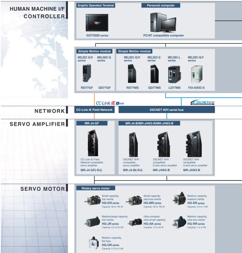
MR-J4-B/MR-J4W2-B/MR-J4W3-B SSCNET III/H serial bus
HUMAN MACHINE I/F
N E T W O R K
S E RV O A M P L I F I E R
S E RV O M O TO R
C O N T R O L L E R
SSCNET III/H compatible servo amplifier
MR-J4-B(-RJ)
SSCNET III/H compatible 2-axis servo amplifier
MR-J4W2-B
SSCNET III/H compatible 3-axis servo amplifier
MR-J4W3-B
Graphic Operation Terminal Personal computer
MR-J4-GF
CC-Link IE Field Network compatible servo amplifier
MR-J4-GF(-RJ)
CC-Link IE Field Network
GOT2000 series PC/AT compatible computer
Rotary servo motor
Simple Motion module Simple Motion module
RD77GF MELSEC iQ-R
series
QD77GF MELSEC-Q
series
RD77MS MELSEC iQ-R
series
QD77MS MELSEC-Q
series
LD77MS MELSEC-L
series
FX5-40SSC-S MELSEC iQ-F
series
Small capacity, ultra-low inertia
Medium capacity, medium inertia
HG-MR series HG-SR series
Small capacity, low inertia
HG-KR series
Capacity: 50 to 750 W Capacity: 50 to 750 W Capacity: 0.5 to 7 kW
Medium capacity, flat type
HG-UR series
Capacity: 0.75 to 5 kW
Medium capacity, ultra-low inertia
HG-RR series
Medium/large capacity, low inertia
HG-JR series
Capacity: 0.5 to 55 kW Capacity: 1 to 5 kW
HG-AK series
Capacity: 10 to 30 W
Ultra-compact, ultra-small capacity
Mitsubishi Servo System
Our Total Solution for Your Satisfaction
As the leading supplier of automation products and solutions worldwide, Mitsubishi Electric, known for its high quality and diverse range of automation products including servo system controllers, servo ampliiers, and servo motors, together with our exclusive engineering software and various networks including "CC‑Link IE Field Network" and "SSCNET III/H", boasts a whole range of solutions speciic to your needs.
2
Pr
o
d
u
c
t
L
in
e
s
Pulse train input SSCNET III/H serial bus Motion controller Positioning module
QD75PN QD75DN RD75P
RD75D
RnMTCPU Q17nDSCPU Q170MSCPU QD70P
QD70D
LD75P LD75D
FX2N-10PG
MELSOFT MT Works2 Motion Controller Engineering Software
MELSOFT MR Configurator2 Servo Setup Software
Capacity Selection Software MELSOFT GX Works2
MELSOFT GX Works3 Programmable Controller Engineering Software
S O F T WA R E
LOW-VOLTAGE SWITCHGEAR
Magnetic contactor
MS-T
Molded-case circuit breaker
WS-V
Programmable controller Personal computer
Embedded type servo system controller
General-purpose interface compatible servo amplifier
MR-J4-A(-RJ)
MR-J4-A
*1. Not all the combinations of the servo amplifier and the servo motor are available. Refer to "MELSERVO-J4 catalog (L(NA)03058)" and "MELSERVO-JE catalog (L(NA)03086ENG)" for the available combinations.
*1
Linear servo motor Direct drive motor
TM-RFM series
Rating: 2 to 240 N·m
LM-H3 series
Rating: 70 to 960 N
Core type with magnetic attraction counter-force
LM-K2 series
Rating: 120 to 2400 N
Core type Core type (natural/liquid cooling)
LM-F series
Rating: 300 to 3000 N (natural cooling) Rating: 600 to 6000 N (liquid cooling)
Coreless type
LM-U2 series
Rating: 50 to 800 N
MELSEC-Q
series
MELSEC iQ-R
series
MELSEC iQ-R
series MELSEC-Qseries MELSEC-Qseries MELSEC iQ-Rseries MELSEC-Qseries MELSEC-Qseries MELSEC-Lseries MELSEC-Fseries
MELSEC-L
series MELSEC iQ-Fseries MELSEC-Fseries
MR-JE-B
MR-JE-B
SSCNET III/H compatible servo amplifier
Pulse train input
MR-JE-A
MR-JE-A
General-purpose interface compatible servo amplifier
Rotary servo motor
HG-KN series
Small capacity, low inertia
Capacity: 100 to 750 W
HG-SN series
Medium capacity, medium inertia
Capacity: 0.5 to 3 kW
MELSEC-Q
series
Q173SCCF MR-MC
series
PC/AT compatible computer
2
Pr
o
d
u
c
t
L
in
e
s
MELSEC iQ-R series
The MELSEC iQ‑R series is equipped with the new, high‑speed system bus, achieving a shorter cycle time.
Simple Motion module
RD77GF The RD77GF is a Simple Motion module compatible with CC‑Link IE Field Network which combines the versatility of Ethernet and highly accurate synchronous operation for Motion control.
The module easily performs various control such as synchronous, cam, and speed‑torque control using only sequence programs.
RD77GF4 RD77GF8 RD77GF16
Number of control axes Up to 4 axes Up to 8 axes Up to 16 axes
Operation cycle 0.5 ms or longer
Servo ampliier MR‑J4‑GF(‑RJ)
Command interface CC‑Link IE Field Network
Simple Motion module
RD77MS The RD77MS is an intelligent function module, easily performing various control such as positioning, synchronous, cam, and speed‑torque (tightening & press‑it) control using only sequence programs.
RD77MS2 RD77MS4 RD77MS8 RD77MS16
Number of control axes Up to 2 axes Up to 4 axes Up to 8 axes Up to 16 axes
Operation cycle 0.444 ms or longer
Servo ampliier MR‑J4‑B(‑RJ)MR‑JE‑B
Command interface SSCNET III/H
Motion controller
RnMTCPU The RnMTCPU is a CPU module performing control using the Motion SFC program, independently of a PLC CPU.
The controller performs various advanced Motion control such as positioning, speed, torque, tightening & press‑it, synchronous, and cam control.
R16MTCPU R32MTCPU R64MTCPU NEW
Number of control axes Up to 16 axes Up to 32 axes Up to 64 axes
Operation cycle 0.222 ms or longer
Servo ampliier MR‑J4‑B(‑RJ)
Command interface SSCNET III/H
Controllers
From simple positioning to multi-axis and high-speed systems
Our extensive product lines cover from Positioning modules, which enables positioning with simple programs, to Simple Motion modules and Motion controllers, which enable advanced control.
NEW
3
C
o
n
tr
o
lle
rs
RD75P2 RD75P4 RD75D2 RD75D4 Number of control axes Up to 2 axes Up to 4 axes Up to 2 axes Up to 4 axes
Startup time 0.3 ms or longer
Servo ampliier MR‑J4‑A(‑RJ)MR‑JE‑A
Command interface Transistor output Differential driver output
MELSEC-Q series
The wide‑range of the MELSEC‑Q series fully meets the control needs in each industry and ield.
Simple Motion module
QD77GFThe QD77GF is a Simple Motion module compatible with CC‑Link IE Field Network which combines the versatility of Ethernet and highly accurate synchronous operation for Motion control.
QD77GF4: 4 axes NEW
QD77GF8: 8 axes NEW
QD77GF16: 16 axes
Simple Motion module
QD77MSThe QD77MS is simple to use just like Positioning modules while capable of performing various control such as positioning, synchronous, cam, and speed‑torque control (tightening & press‑it) using only sequence programs.
QD77MS2: 2 axes QD77MS4: 4 axes QD77MS16: 16 axes
Motion controller
Q17nDSCPUThe Q17nDSCPU is a CPU module used with a PLC CPU for Motion control.
Q172DSCPU: 16 axes Q173DSCPU: 32 axes
Stand-alone Motion controller
Q170MSCPU
The Q170MSCPU is a module integrating a power supply, a PLC, and a Motion controller all in one. Q170MSCPU: 16 axes (Equivalent to Q03UDCPU) Q170MSCPU‑S1: 16 axes (Equivalent to Q06UDHCPU)
3
C
o
n
tr
o
lle
rs
QD75PN/QD75DN
The QD75PN/QD75DN are pulse train output compatible modules. The QD75PN is for transistor output, and the QD75DN is for differential driver output.
QD75P1N/QD75D1N: 1 axis QD75P2N/QD75D2N: 2 axes QD75P4N/QD75D4N: 4 axes
QD70P/QD70D
The QD70P/QD70D are pulse train output compatible modules. These modules enable smooth acceleration/ deceleration with frequent speed changes and are suitable for connecting to stepping motors. QD70P4/QD70D4: 4 axes QD70P8/QD70D8: 8 axes
MELSEC-L series
The MELSEC‑L series is a baseless highly scalable controller ideal for applications having limited space.
Simple Motion module
LD77MSThe LD77MS is simple to use just like Positioning modules while capable of performing various control such as positioning, synchronous, cam, and speed‑torque (tightening & press‑it) control.
LD77MS2: 2 axes LD77MS4: 4 axes LD77MS16: 16 axes
SSCNET III/H Head module
LJ72MS15The SSCNET III/H head module is used to connect the MELSEC‑L series
I/O module and intelligent function
module to SSCNET III/H.
Positioning module
LD75P/LD75DThe LD75P/LD75D are pulse train output compatible modules. The LD75P is for transistor output, and the LD75D is for differential driver output.
LD75P1/LD75D1: 1 axis LD75P2/LD75D2: 2 axes LD75P4/LD75D4: 4 axes
PLC CPU module (built-in positioning function)
LCPUThe positioning function, equipped as standard, outputs command pulses to a servo ampliier by using the built‑in I/O function.
Control axes: 2 axes
Embedded Type Servo System Controllers
High‑response servo control is achieved with a combination of the Position Board and a personal computer, or the C Controller Interface Module and the C Controller via PCI Express®.
Position Board
MR-MC240/MR-MC241 The MR‑MC240/MR‑MC241 areboard type controllers used by being embedded in a personal computer for
controlling MR‑J4‑B through a user program.
MR‑MC240: 20 axes MR‑MC241: 32 axes
C Controller Interface module
Q173SCCFThe Q173SCCF is an intelligent
module used by being connected
directly to a C Controller via PCI Express® for controlling MR‑J4‑B through a user program. Q173SCCF: 20 axes
3
C
o
n
tr
o
lle
rs
built‑in functions.
In cooperation with driving devices, the FX5‑40SSC‑S achieves advanced motion control.
FX5‑40SSC‑S
Number of control axes Up to 4 axes
Servo ampliier MR‑J4‑B(‑RJ)MR‑JE‑B
Command Interface SSCNET III/H
PLC CPU module (built-in positioning function)
FX5U/FX5UC series The FX5U/FX5UC series features positioning functionality with 4‑axis pulse output. In addition, Positioning operations including interrupt, variable speed, and simple interpolation are easily set up in tables and executed.
FX5U/FX5UC series
Number of control axes Up to 4 axes
Servo ampliier MR‑J4‑A(‑RJ)MR‑JE‑A
Command Interface Pulse train
MELSEC-F series
Positioning module
FX3U-1PG/FX2N-10PGThis pulse train output block is used with the FX series programmable controller. The FX2N‑10PG model is
capable of high‑speed and high‑precision positioning at a maximum of 1 MHz high‑speed pulses.
FX3U‑1PG: 1 axis
FX2N‑10PG: 1 axis
Positioning module
FX2N-10GM/FX2N-20GMThis Positioning module is used independently or with the FX series programmable controller.
The FX2N‑20GM model supports
2‑axis interpolation control. FX2N‑10GM: 1 axis
FX2N‑20GM: 2 axes
FX2N‑20GM
FX2N‑10PG
3
C
o
n
tr
o
lle
rs
Servo Ampliiers
From the industry's top level high‑speed, high‑accuracy servos to one‑touch servos and multi‑axis models. In addition to the high‑end MELSERVO‑J4 series, a variety of models to match various applications is available.
The Mitsubishi Electric's servo ampliiers support motors from rotary servo motors to linear servo motors and direct drive motors, and greatly enhance system performance.
~Man, Machine, and Environment in Perfect Harmony~
MELSERVO-J4 series
MELSERVO‑J4 series is the newest member to the MELSERVO family, backed by Mitsubishi Electric's leadership in all‑digital technology. With safety, Ethernet‑based CC‑Link IE Field Network, SSCNET III/H high‑speed optical communication and energy‑eficient design of the new MELSERVO‑J4 series ‑ man, machine, and environment can at last work together in perfect harmony.
MR-J4-GF(-RJ) *1
CC-Link IE Field Network compatible
servo ampliier
This servo ampliier is compatible with CC‑Link IE Field Network. Together with the Simple Motion module, advanced synchronous control and interpolation control by sequential commands are enabled. The servo ampliier has a built‑in point table function, offering easy positioning with a combination with a master module.
Command interface CC‑Link IE Field Network
Control mode Position/Speed/Torque/Fully closed loop
Power supply 200 V AC 400 V AC
Capacity range 0.1 kW to 7 kW 0.6 kW to 7 kW
Compatible servo motor Rotary servo motor, linear servo motor, DD motor
MR-J4-B(-RJ) *1
MR-J4W2-B/MR-J4W3-B
SSCNET III/H compatible servo ampliier
A complete synchronous system with SSCNET III/H can be conigured using 0.222 ms cycle high‑speed serial communication between the controller and the servo ampliier.
2‑axis/3‑axis servo ampliiers are also available, enabling energy‑conservative, less‑wiring, compact machine at lower cost.
Command interface SSCNET III/H
Control mode Position/Speed/Torque/Fully closed loop
Power supply 100 V AC 200 V AC 400 V AC
Capacity range 0.1 kW to 0.4 kW 0.1 kW to 37 kW 0.6 kW to 55 kW
Compatible servo motor Rotary servo motor, linear servo motor, DD motor
MR-J4-A(-RJ) *1
General-purpose interface compatible
servo ampliier
Pulse train and analog input, etc., are provided as a standard for the command interface. The control mode can be switched accordingly for position, speed or torque control. The MR‑J4‑A‑RJ has a built‑in positioning function, being compatible with MODBUS®, simple cam, and mark sensor input compensation.
Command interface Pulse train/Analog voltage/RS‑422/MODBUS®
RTU
Control mode Position/Speed/Torque/Fully closed loop
Power supply 100 V AC 200 V AC 400 V AC
Capacity range 0.1 kW to 0.4 kW 0.1 kW to 37 kW 0.6 kW to 55 kW
Compatible servo motor Rotary servo motor, linear servo motor, DD motor
MR-J4W2-0303B6 MR-J4-03A6(-RJ) *1
Ultra-small capacity servo ampliier
This servo ampliier is compatible with the ultra‑compact HG‑AK servo motor series (10 W to 30 W) and two types of main circuit power supply of 48 V DC and 24 V DC, being suitable for compact machines. 2‑axis servo ampliiers are also available.
Command interface SSCNET III/H or Pulse train/Analog voltage/RS‑422
Control mode Position/Speed/Torque
Power supply 48 V DC/24 V DC
Capacity range 10 W to 30 W
Compatible servo motor Rotary servo motor
*1. MR‑J4‑GF‑RJ, MR‑J4‑B‑RJ, MR‑J4‑A‑RJ and MR‑J4‑03A6‑RJ are servo ampliiers with special speciication.
NEW
4
Se
rv
o A
m
plii
ers
Industry-leading Level of Servo Ampliier Basic Performance
Speed frequency response of 2.5 kHz is achieved by applying our original high‑speed servo control architecture evolved from the conventional two‑degrees‑of‑freedom model adaptive control to the dedicated execution engine. Together with a high‑resolution absolute position encoder of 4,194,304 pulses/rev, fast and accurate operation is enabled. The performance of the high‑end machines is utilized to the fullest.
[Settling time comparison with the prior model] [Dedicated execution engine]
* The result is based on our evaluation condition.
Command Torque Droop pulses In-position [MR-J3] Settling time [MR-J4] Settling time Settling time reduced by 40%*
Servo amplifier control loop
Position control Model-based control Speed control Current control Command Servo motor Dedicated execution engine
One-touch Tuning
Just turn on the one‑touch tuning function to complete servo gain adjustment automatically, including machine resonance ilter, advanced
vibration suppression control II*1, and robust ilter for maximizing your machine performance. This function also sets responsivity automatically, while the real‑time auto tuning requires manual setting. Moreover, a new method*2 allows to create an optimum tuning command inside the servo ampliier.
Sp e e d Sp e e d Sp e e d Time Settling time Settling time Time Time
: Command : Actual operation
Operation is unstable. Operation is not followingthe command.
Before After
Exactly matched. High-speed positioning.
Vibration suppression control and robust filter adjustment with one-touch.
*1. The advanced vibration suppression control II automatically adjusts one frequency.
*2. This new method is available with MR‑J4‑B/MR‑J4W_‑B/MR‑J4‑A with software version of C1 or later.
Advanced Vibration Suppression Control II
The advanced vibration suppression control II suppresses two types of low frequency vibrations owing to vibration suppression algorithm which supports three‑inertia system. This function is effective in suppressing residual vibration with relatively low frequency of approximately 100 Hz or less generated at the end of an arm and in a machine, enabling a shorter settling time.
Application examples
[Pick and place robots] [Automatic assembly equipment] [Material handling systems] Vibration at the end
of an arm
Vibration in a machine
Two types of the vibrations are
suppressed at the same time. Three-inertia
system Without vibration
suppression control
Advanced vibration suppression control II
Lost Motion Compensation Function
This function suppresses quadrant protrusion caused by friction and torsion generated when the servo motor rotates in reverse direction. Therefore, the accuracy of circular path will be improved in trajectory control used in XY table, etc.
* This function is not available with MR‑J4W2‑B and MR‑J4W3‑B.
X X
Suppression of quadrant protrusion of circular trajectory
Before After
Y Y
Validate the lost motion compensation
function.
Built-in Positioning Function
MR‑J4‑A‑RJ has a built‑in positioning function, enabling positioning operation with point table, program‑based, and indexer (turret) methods. With this servo ampliier, a positioning system is conigured without a Positioning module (command pulse). Positioning command is executed by input/output signals or RS‑422/ RS‑485 communication (up to 32 axes). * MR‑J4‑03A6‑RJ is not compatible with RS‑485
communication.
[Program example] [Indexer (turret) method] 256
programs max
Program No. 1 SPN (3000) STC (20) MOV (1000) TIM (100) FOR (3) MOVI (100) TIM (100) NEXT STOP
q w e
Station No. 0 Station No. 1
Station No. 2 Station No. 3
Station No. 4 Station No. 5
Station No. 6 Station No. 7 [Point table example]
Point table No.
1 2
255
1000 2000
3000
2000 1600
3000
200 100
100
200 100
100
0 0
0
1 0
2
1 2
99 Position
data Servo motorspeed time constantAcceleration time constantDeceleration Dwell functionSub M code
For Compact Machines
Ultra‑compact servo motors combined with ultra‑small capacity servo ampliiers compatible with the main circuit power supply of
48 V DC/24 V DC are best suited for compact machines. The following servo ampliiers are available: 2‑axis with SSCNET III/H interface and general‑purpose interface with the built‑in positioning function.
HG‐AK MR‐J4‐03A6(‐RJ) MR‐J4W2‐0303B6
25 × 25 H100 × W30 × D90
for one axis H168 × W30 × D100 for two axes
[Unit: mm]
4
Se
rv
o A
m
plii
ers
Compatible with CC-Link IE Field Network
NEWMR-J4-GF(-RJ) is compatible with CC-Link IE Field Network as standard.
The servo ampliier is connectable with Ethernet-based CC-Link IE Field Network, enabling high-speed, seamless communication.
Easy Positioning with CC-Link IE Field Network
NEWA combination of a master module and MR-J4-GF(-RJ) allows positioning operation with point table method, not requiring a Positioning module. Just set the point table No. and turn on the start signal, and then the positioning operation will be started.
Automatic continuous operation of the next point table is also possible without stopping.
Point table No. 1 Point table No. 2 [Operation]
Speed
[Point table example]
Point table No.
1
2
255
1000 2000
3000
2000 1600
3000
200 100
100
200 100
100
0 0
0
1 0
2 Position
data Servo motorspeed time constantAcceleration time constantDeceleration Dwell M code
1000 2000
2000 1600
0 Position address Start signal
CC-Link IE Field Network Motion Control
NEWA combination of a Simple Motion module and
MR‑J4‑GF(‑RJ) enables high‑performance synchronous control and interpolation control with simple parameter setting and a start from a sequence program. Speed control and torque control are also possible, suitable for converting machines.
In addition, using remote inputs/outputs which are compatible with the synchronized communication function enables a system synchronized with the command cycle of the servo ampliier.
1st servo amplifier axis 2nd servo amplifier axis 3rd servo amplifier axis
1st servo amplifier axis 2nd servo amplifier axis 3rd servo amplifier axis
Receives position command.
Receives position command.
Pulse train command (asynchronous)
CC-Link IE Field Network command (synchronous)
MR‑J4‑GF
4
Se
rv
o A
m
plii
ers
Harmony with Man
The leading edge in safety and convenience, designed to harmonize with the way you work.
Functions According to IEC/EN 61800-5-2
STO (Safe torque off) and SS1*1 (Safe stop 1)
are integrated as standard, enabling the safety system to be conigured easily in the machine. ● By using STO, it is not necessary to turn off
the control power of the servo ampliier, resulting in shorter restart time. In addition, home position return is not also necessary. ● Magnetic contactor for preventing unexpected
motor start is not needed.*2
● The safety level of STO is increased to SIL 3 from SIL 2. *3 NEW
[Shut-off by STO] [Shut-off by STO and SS1]
Servo amplifier
Servo amplifier
Servo motor Servo motor
Magnetic contactor for preventing unexpected start is no longer required.
Magnetic contactor for preventing unexpected start is no longer required.
Stops
motor Stopsmotor
Molded-case circuit breaker (MCCB) Safety
relay circuit
Magnetic contactor (MC) for servo alarm *2
Molded-case circuit breaker (MCCB)
Magnetic contactor (MC) for servo alarm *2
SS1 signal Shut-off
Safety equipment
MR-J3-D05, safety programmable controller MELSEC QS/WS series, etc.
IEC/EN 61800‑5‑2:2007 function Safety level
STO (Safe torque off) Category 3, PL e, SIL 3 *3
SS1 (Safe stop 1) *1
*1. Safety equipment (MR‑J3‑D05, safety programmable controller MELSEC QS/WS series, etc.) is required.
*2. For MR‑J4 series servo ampliier, magnetic contactors are not required to meet the STO requirements. However, this igure has a magnetic contactor installed to prevent servo alarms and electric shock.
*3. Category 3, PL e, SIL 3 is achievable with the servo ampliiers manufactured in Japan in June 2015 or later, and in China in December 2015 or later. Note that parameter setting is required.
Achieving Category 4, PL e, SIL 3 by wiring to functional safety unit
Category 4 PL e, SIL 3 is achieved when the safety signals are inputted directly to MR‑D30 functional safety unit.
Because the safety observation function is operated on the MR‑D30 side, expansion of the safety observation function is possible independent of controllers, offering a selection from a wide variety of controllers such as Simple Motion modules, Motion controllers, and Positioning modules. Moreover, the safety observation function is easily enabled by parameter setting. Servo motors with functional safety are now available. (HG‑KR_W0C/HG‑SR_W0C/HG‑JR_W0C)
IEC/EN 61800‑5‑2:2007 function Safety level
STO (Safe torque off)
Category 4 PL e, SIL 3 SS1 (Safe stop 1)
SS2 (Safe stop 2) *1 SOS (Safe operating stop) *1 SLS (Safely‑limited speed) *2 SBC (Safe brake control) SSM (Safe speed monitor) *2
*1. SS2 and SOS are achievable with the use of the servo motor with functional safety unit.
*2. The safety level would be Category 3 PL d, SIL 2 when the servo motor with functional safety is not used.
SSCNET III/H compatible controller
Servo motor with functional safety
To other servo amplifier axes
Light curtain Safety switch WS0-CPU0 WS0-CPU1 etc. Safety controller Safety signal Safety signal
To other servo amplifier axes
Light curtain Safety switch WS0-CPU0 WS0-CPU1 etc. Safety controller Safety signal Safety signal Safety input/output via DI/O (STO/SS1/SS2/SOS/SBC/SLS/SSM)
Safety input/output via DI/O (STO/SS1/SS2/SOS/SBC/SLS/SSM)
Servo motor with functional safety MR-J4-B-RJ MR-D30 MR-J4-A-RJ MR-D30
[For general-purpose pulse train command (MR-J4-A-RJ + MR-D30)]
Tough Drive Function
Instantaneous power failure tough drive
When an instantaneous power failure is detected, this function allows the servo ampliier to use the electric energy charged in the main circuit capacitor in the servo ampliier to avoid an alarm occurrence, increasing the machine availability even with an unstable power supply.
Vibration tough drive
Machine resonance suppression ilter is automatically readjusted when a change in machine resonance frequency is detected by the servo ampliier. Losses from the machine stop due to age-related deterioration are reduced.
Motor current Vibration detected
Suppresses vibration by readjusting the machine resonance suppression filter.
Servo motor speed
Undervoltage
Tough drive enabled
Tough drive disabled
Operation continues even with instantaneous power failure.
Large Capacity Drive Recorder
Servo data such as motor current and position command before and after the alarm occurrence are stored in non-volatile memory of the servo ampliier. Reading the servo data on MELSOFT MR Conigurator2 helps you analyze the cause of the alarm.
Alarm No., waveform, and monitor value at alarm occurrence are displayed in MR Configurator2.
Waveform display Monitor value display Data are stored
in non-volatile memory at alarm
occurrence.
Data over certain period of time are stored in the memory.
Lowered bus voltage It is revealed that the main circuit power is turned off.
Machine Diagnosis Function
This function detects changes of machine parts (ball screw, guide, bearing, belt, etc.) by analyzing machine friction, load moment of inertia, unbalanced torque, and changes in vibration component from the data inside the servo ampliier. When MELSEC iQ-R Motion controller is used, the diagnosed data is monitored with the optional data monitor function, supporting timely maintenance of the driving parts.
Servo amplifier
Encoder
[Machine diagnosis function window on MR Configurator2]
Servo motor Ball screw
Friction and vibration are estimated based on the data in a normal operation. Particular measurement is not required.
Estimated friction value is displayed
Estimated vibration value is displayed
4
Se
rv
o A
m
plii
ers
Harmony with the Environment
The new MR-J4 series: an evolution in eco-friendly design, and that's winning acclaim worldwide.
Expanded Environmental Conditions
Capable of operating at an altitude of up to 2000 m.
NEWCompatible with power supply voltage of 240 V AC for global use.
Complies with RoHS directive.
Servo ampliiers with special coating-speciication are now available. This servo ampliier has an improved corrosion resistance in environments with corrosive gas concentrations, conforming to IEC 60721-3-3, Class 3C2. For details, contact your local ofice.
2-axis/3-axis Types for Energy-conservative, Miniaturized, and Low-cost Machine
2-axis and 3‑axis servo ampliiers are available for operating two and three servo motors, respectively. These servo ampliiers enable energy‑conservative, compact machine at lower cost. Different types of servo motors including rotary servo motors, linear servo motors, and direct drive motors are freely combined as long as the servo motors are compatible with the servo ampliier.
C-axis direct drive motor (TM-RFM)
MR-J4W3-B
A-axis rotary servo motor (HG-KR/MR)
B-axis linear servo motor (LM-H3/K2/U2)
Operates any combination of rotary servo motors, linear servo motors,
and direct drive motors with various series and capacities.
Supporting Energy-conservative Machine Using Regenerative Energy
In the multi‑axis servo ampliier,
the regenerative energy of an axis is used as driving power energy for the other axes, contributing to energy‑conservation of machine.
Reusable regenerative energy stored in
the capacitor is increased for MR‑J4W2‑B/ MR‑J4W3‑B as compared to the prior model. Regenerative option is no longer required*. * Regenerative option may be required depending on
the conditions.
A-axis motor speed
Deceleration Time
200 W 400 W
[Reusable energy]
21 J 30 J
9 J 11 J
MR-J4W3 MR-J3
B-axis motor speed
Time
C-axis motor speed
Acceleration
Time
A-axis motor
B-axis motor
C-axis motor
Driving power energy Regenerative energy
Regenerative energy is temporarily stored and used as driving
power energy. Driving power energy Acceleration
4
Se
rv
o A
m
plii
ers
Space-saving with Industry's Smallest* 3-axis Type
2-axis servo ampliier MR‑J4W2‑B requires 26% less installation space than two units of MR‑J4‑B. 3‑axis servo ampliier MR‑J4W3‑B requires 30% less installation space than three units of MR‑J4‑B.
* Based on Mitsubishi Electric research as of February, 2015.
MR-J4-B (Depth 135 mm, 170 mm, 185 mm)
100 W 40
100 W 200 W 200 W 400 W 750 W 60
750 W
MR-J4W2-B (3-axis type) MR-J4W3-B
(3-axis type) (Depth 195 mm)
255 mm = 85 mm (unit width) × 3
Installation space reduced by Installation space reduced by
30
% 85100 W × 2 200 W × 1
200 W × 1 400 W × 2
750 W × 2
400 W
Industry's smallest*
[Example of installation space for two units of each 100 W, 200 W, 400 W, and 750 W]
(Depth 195 mm)
100 W × 2 60 200 W × 2
26
% 750 W × 2 85 400 W × 2360 mm = 40 mm (unit width) × 6 + 60 mm (unit width) × 2 265 mm = 60 mm (unit width) × 3 + 85 mm (unit width) × 1
168 mm 168 mm
168 mm
Reduced Wiring by Approx. 50% with 3-axis Type
The three axes of 3‑axis servo ampliier MR‑J4W3‑B use the same connections for main and control circuit power, peripheral equipment, control signal wire, etc. Thus, the number of wirings and devices is greatly reduced. MCCB MC MCCB MC MCCB MC MCCB MC
[Comparison of the number of wirings]
MR-J4W3-B (3-axis type) × 1 unit MR-J4-B × 3 units
Reduced wiring by 50% Controller Controller SSCNET III/H Main circuit power supply Control circuit power supply Magnetic contactor connection Magnetic contactor control Encoder Motor power input
Total 21
[Number of wirings]
SSCNET III/H Main circuit power supply Control circuit power supply Magnetic contactor connection Magnetic contactor control Encoder
Motor power input
× 1 × 1 × 1 × 1 × 1 × 3 × 3 Total 11
[Number of wirings]
× 3 ( )
× 3 ( )
× 3 ( )
× 3 ( )
× 3 ( )
× 3 ( )
× 3 ( )
Heritage
A heritage of trust and continuity — the hallmark of every MELSERVO product.
Easy Replacement of MR-J3 Series
MR-J4-B/MR-J4-A has the same mounting
dimensions*1 with MR-J3-B/MR-J3-A. HG rotary
servo motor series has the same mounting
dimensions*2 and uses the same optional cables
for the power, the encoder*3, and
the electromagnetic brake as HF series or
HC-RP/HC-UP series. Servo motor power cable
Encoder cable
MR-J4-B MR-J4-A
Servo motor Same mounting
dimensions with MR-J3
Same mounting dimensions of
servo motor Same cables with
MR-J3
*1. Mounting dimensions are smaller for servo ampliiers rated 200 V 5 kW, 400 V 3.5 kW, 200 V/400 V 11 kW, and 200 V/400 V 15 kW. *2. For replacing HA-LP series to HG-JR series, contact your local sales ofice for more detail.
*3. HG-JR series of 11 kW to 55 kW uses a different encoder cable from HF-JP series.
Supporting Replacement of MR-J2-Super Series
MELSERVO-J4 series product lines include general-purpose interface, positioning function, and SSCNET III/H interface. MELSERVO-J4 series is compatible with a wide variety of
command interface and also replaceable from
MELSERVO-J2S series.
MR-J2S-A
MR-J2S-B
MR-J2S-CP
MR-J2S-CL
MR-J4-A
MR-J4-B
MR-J4-A-RJ
We provide support for the renewal with the following materials from the catalog of renewal introduction, the handbook with detailed information to the instruction manual for the renewal tool to use the existing connections.
100 V AC type is added to product lines for MR-J4-B-RJ020 servo amplifier for connecting to SSCNET of MR-J2S-B.
By using the conversion unit for SSCNET of MR-J2S-B, MR-J4 series servo amplifier can be connected to the SSCNET of MR-J2S-B compatible servo system controller *. MR-J4-B-RJ020 is now available in the following capacities:
200 V 0.1 kW to 22 kW, 100 V 0.1 kW to 0.4 kW, and 400 V 0.6 kW to 22 kW
* For compatible controllers, refer to p. 1 in this brochure.
NEW
March 2014
New Product Release
S V 1 3 0 6 - 1 E - B
General-Purpose AC Servo MELSERVO-J4 Conversion Unit for SSCNET of MR-J2S-B Compatible Servo Amplifier: MR-J4-B-RJ020 Conversion Unit for SSCNET of MR-J2S-B: MR-J4-T20
Conversion Unit for SSCNET of MR-J2S-B Compatible Servo Amplifier: MR-J4-_B_-RJ020 Conversion Unit for SSCNET of MR-J2S-B: MR-J4-T20
●A combination of MR-J4-B-RJ020 and MR-J4-T20 is capable of connecting to the SSCNET of MR-J2S-B compatible servo system controller and drives MR-J4 compatible HG series servo motors.
●Use the existing program.
* For the outline of precautions, refer to p. 2 in this brochure. Refer to "MR-J4-_B_-RJ020 MR-J4-T20 Servo Amplifier Instruction Manual" for details.
Transition from MELSERVO‑J2‑Super/J2M Series to J4 Series Handbook
L(NA)03093
This handbook explains how to replace your MR‑J2S/J2M to MR‑J4 series.
New Product Release of Conversion Unit for SSCNET of MR‑J2S‑B
SV1306‑1
This brochure announces a new release of MR‑J4‑B‑RJ020 and a conversion unit for connecting to SSCNET of MR‑J2S‑B. Speciications of the servo ampliier and the conversion unit are also listed.
MR‑J2S Renewal Tool Catalog X901307‑312
This guide introduces a renewal tool for replacing MR‑J2S to MR‑J4. The renewal tool allows to use the existing wiring and mounting holes, making the replacement simple and fast. Mitsubishi Electric System & Service Co., Ltd.
4
Se
rv
o A
m
plii
ers
[High Performance]
The dedicated engine enables speed frequency response of 2.0 kHz, shortening the cycle time.
The large capacity main circuit capacitor allows the regenerative energy to be used effectively.
[Global Standard]
Global servo, MR-JE series, complies with global standards as standard.
Command pulse input and digital input/output are compatible with both sink and source type connections.
MR-JE-B
SSCNET III/H compatible
servo ampliier
MR-JE-B is compatible with SSCNET III/H, optical servo system controller network that
enables a high-response and multi-axis system with high synchronous performance and
less wiring. In addition, absolute position detection system can be conigured easily with the MR‑JE‑B servo ampliiers.
Command interface SSCNET III/H
Control mode Position/Speed/Torque
Power supply 200 V AC
Capacity range 0.1 kW to 3 kW
Compatible servo motor Rotary servo motor
MR-JE-A
General-purpose interface compatible
servo ampliier
Pulse train and analog input, etc., are provided as a standard for the command interface. The control mode can be switched accordingly for position, speed or torque control. The MR‑JE‑A has a built‑in positioning function, being compatible with MODBUS®, simple cam, and mark sensor input compensation.
Command interface Pulse train/Analog/RS‑422/MODBUS®
RTU
Control mode Position/Speed/Torque
Power supply 200 V AC
Capacity range 0.1 kW to 3 kW
Compatible servo motor Rotary servo motor
4
Se
rv
o A
m
plii
ers
Servo Motors
From rotary to linear and direct drive motors
Rotary servo motors are available in capacities from 10 W to 55 kW.
Linear servo motors and direct drive motors satisfy new needs in driving control by providing high rigidity, performance and lexibility in system conigurations unique to a direct drive.
Rotary servo motor: A wide range of capacities and series for various system applications
HG series for MELSERVO-J4 series
HG-KR/HG-MR HG‑KR: Small capacity, low inertia. Perfect for general‑purpose industrial machines. HG‑MR: Small capacity, ultra‑low inertia. Perfect for high‑throughput operations. Capacity: 50 W to 750 W Rated speed: 3000 r/min Maximum speed: 6000 r/min [Application example]
Inserters, mounters and bonders PCB drilling machines
In‑circuit testers and label printers Knitting and embroidery machines Compact robots and robot hand sections
HG-SR Medium capacity, medium inertia. Suitable for machines having large load inertia. Capacity: 0.5 kW to 7 kW Rated speed: 1000 r/min and 2000 r/min
[Application example]
Material handling systems Dedicated machines Robots
Loaders and unloaders Winders and tension units Turrets X‑Y tables
HG-JR Medium to large capacity, low inertia. Perfect for high‑throughput positioning or high acceleration/deceleration operations.
Capacity: 0.5 kW to 55 kW Rated speed: 1000 r/min, 1500 r/min, and 3000 r/min [Application example]
Food packaging machines Printers Injection molding machines Press machines
HG-AK Ultra‑compact, ultra‑small capacity with lange size of 25 mm. Suitable for small machines. Capacity: 10 W to 30 W Rated speed: 3000 r/min Maximum speed: 6000 r/min
[Application example]
Mounters and bonders Semiconductor manufacturing equipment Compact robots Electric component manufacturing machines Compact X‑Y table
HG-RR Medium capacity, ultra‑low inertia. Perfect for high‑throughput operation. Capacity: 1 kW to 5 kW Rated speed: 3000 r/min
[Application example]
Roll feeders Loaders and unloaders Ultra high‑throughput material handling systems
HG-UR Medium capacity, lat type. Perfect for applications with limited mounting space. Capacity: 0.75 kW to 5 kW Rated speed: 2000 r/min
[Application example]
Robots Conveyors Winders and tension machines Food processing machines
5
Se
rv
o
Mo
to
rs
Servo motors are equipped with a high-resolution absolute position encoder of 4,194,304 pulses/rev (22-bit) as standard. Positioning accuracy is increased.
* 262,144 pulses/rev (18-bit) for HG-AK series.
Improved Environmental Resistance
HG-KR/HG-MR/HG-RR/HG-UR, HG-SR/HG-JR, and HG-AK are rated IP65, IP67*1, and IP55, respectively.*2
*1. HG-JR1000 r/min series 15 kW or larger, and HG-JR1500 r/min series 22 kW or larger are rated IP44.
*2. The shaft-through portion is excluded.
Protected from water and dust.
Cable Leading Direction
Cables for power, encoder, and electromagnetic brake are capable of connecting either in direction or in opposite direction of the load side, depending on the cable selection. (HG‑KR and HG‑MR series)
In direction of load side
In opposite direction of load side Selectable mounting direction
Reduced Torque Ripple during Conduction
The torque ripple is reduced owing to the optimized combination of the numbers of the motor poles and the slots. Thereby, smooth rotation is achieved even during a low‑speed operation which is more likely affected by the torque ripple, improving the operation stability.
[New model (HG-KR series)] [Prior model (HF-KP series)]
* For 400 W Torque ripple
1/4
As compared to the prior series.HG series for MELSERVO-JE series
HG-KN Small capacity, low inertia. Perfect for general‑purpose industrial machines. Capacity: 0.1 kW to 0.75 kW Rated speed: 3000 r/min
[Application example]
Inserters, mounters and bonders PCB drilling machines
In‑circuit testers and label printers Knitting and embroidery machines Compact robots and robot hand sections
HG-SN Medium capacity, medium inertia. Suitable for machines having large load inertia. Capacity: 0.5 kW to 3 kW Rated speed: 2000 r/min
[Application example]
Material handling systems Dedicated machines Robots
Loaders and unloaders Winders, tension units Turrets X‑Y tables
5
Se
rv
o
Mo
to
rs
LM series for MELSERVO-J4 series
LM-H3 series Maximum speed: 3 m/s Rated thrust: 70 N to 960 N
Core type suitable for space‑saving.
The magnetic attraction force contributes to high rigidity.
LM-F series Maximum speed: 2 m/s Rated thrust: 300 N to 3000 N (natural cooling), 600 N to 6000 N (liquid cooling)
Core type compact linear servo motor.
The integrated liquid‑cooling system doubles the continuous thrust. The magnetic attraction force contributes to high rigidity.
LM-K2 series Maximum speed: 2 m/s Rated thrust: 120 N to 2400 N
Core type with magnetic attraction counter‑force.
The magnetic attraction counter‑force structure extends life of the linear guides and contributes to lowering audible noise.
LM-U2 series Maximum speed: 2 m/s Rated thrust: 50 N to 800 N
Coreless type without cogging resulting in small speed luctuation.
The structure with no magnetic attraction force extends life of the linear guides.
Sophisticated Performance
Supporting maximum speed of 3 m/s (LM‑H3 series) and maximum thrust of 150 N to 18000 N.
Small size and high thrust are achieved by the increased winding density and the optimized core and magnet geometries as a result of electromagnetic ield analysis.
Diverse product lines include core, liquid‑cooling core, magnetic attraction counter‑force core, and coreless types.
A/B/Z‑phase differential output type linear encoders are also supported by MR‑J4‑GF‑RJ/MR‑J4‑B‑RJ/MR‑J4‑A‑RJ servo ampliiers.
A combination of the MR‑J4 series servo ampliier and CC‑Link IE Field Network or SSCNET III/H compatible controller achieves advanced system including high‑accuracy tandem synchronous control.
[Application example]
Tandem configuration
Multi-head configuration
Application Example
[Machine tools XYZ stage] [Semiconductor/LCD manufacturing systems] [Screen printing systems]
5
Se
rv
o
Mo
to
rs
[Application example]
Material handling systems LCD manufacturing systems Machine tools
Sophisticated Performance
[High performance due to the latest technologies]
Our latest magnetic design and winding technologies enable high torque density. In addition, extremely smooth rotation is achieved by the minimized torque ripple.
[Compact and low‑proile design]
Due to high level of structural design technology, compact and low‑proile design is achieved. This design enables a small mounting space and a low center of gravity.
[20‑bit high‑resolution absolute position encoder]
The direct drive motor is equipped with 20‑bit high‑resolution absolute position encoder (1,048,576 pulses/rev) as standard. High‑accuracy machine is achieved.
[Hollow shaft diameter range: ø20 mm to 104 mm]
The motor is equipped with a large hollow shaft resulting from using bearing and encoder with large diameter. It allows cables and air tubing to pass through.
Application Example
Suitable for low speed and high torque applications.
[Index table for machine tools] [Rotary axis for material handling robots] [Painting and vapor deposition systems]
[Spin‑type cleaning systems for LCD/semiconductor] [LCD/semiconductor testing systems (XYθ tables)] [Rotary axis for polishing systems]
Polish part
Material handling/ loader part
5
Se
rv
o
Mo
to
rs
Engineering Software
FA Integrated Engineering Software MELSOFT iQ Works
MELSOFT iQ Works is an integrated software suite consisting of GX Works3, MT Works2, GT Works3, RT ToolBox2 mini and FR
Conigurator2, which are programming software for each respective product. Integration is further enhanced with MELSOFT Navigator as the central system coniguration incorporating an easy-to-use, graphical user interface with additional project-sharing features such as system labels and parameters. The advantages of this powerful integrated software suite are that system design is made much easier with a substantial reduction in repetitious tasks, cutting down on errors while helping to reduce the overall TCO.
System management software
MELSOFT Navigator
System level graphic-based coniguration tool that simpliies the system design by providing a visual representation of the system. System management features such as system-wide
parameterization, labels and block reading of project data are also included.
Programmable controller engineering software
MELSOFT GX Works3
GX Works3 is the latest generation of programming and maintenance software offered by Mitsubishi Electric speciically designed for the MELSEC iQ-R Series control system. It includes many new features such as graphic-based system coniguration, integrated motion control setup, multiple language support, providing an intuitive engineering environment solution.
HMI/GOT screen design software
MELSOFT GT Works3
This graphic operation terminal (GOT) screen creation software is designed with three main features—simplicity, graphics design and operation ease—that help to create graphic screens in fewer steps.
Motion controller engineering software
MELSOFT MT Works2
This motion control design and maintenance software includes intuitive graphic-based programming together with a digital oscilloscope simulator.
Robot engineering software
MELSOFT RT ToolBox2 mini
This robot setup software supports various steps from programming, to commissioning, evaluation, and maintenance. In addition, improved preventative maintenance is realized through the use of an integrated 3D robot simulator.
Inverter setup software
MELSOFT FR Conigurator2
This software simpliies the setup and maintenance of AC Inverters. Parameters can be registered easily and distributed to multiple inverters when replacing, and activation of the PLC function all from one setup screen.
6
En
g
in
e
e
rin
g
So
ftw
a
re
startup, and operation and maintenance to facilitate all aspects from speciication review to daily data collection.
Programmable Controller Engineering Software
MELSOFT
GX Works3
Motion Controller Engineering Software
MELSOFT
MT Works2
Servo Setup Software
MELSOFT
MR Conigurator2
All-in-one Tool
for Quick and Easy Startup
This all integrated software offers a wide range of features - sequence program and function block creation, parameter settings for Simple Motion modules, servo adjustment, and debugging.
Harness the Full Potential of Motion
Performance through MELSOFT MT Works2
MELSOFT MT Works2 supports the entire product development cycle - parameter settings, Motion SFC programming, servo adjustment to debugging for Motion controller.
User-friendly Software for Easy
Setup, Tuning and Operation
By being connected to a servo ampliier,
tuning, monitoring, diagnosis, reading/writing
parameters, and test operations are easily performed.
System Design
System coniguration
GX Works3
MT Works2
Servo ampliiers and modules are set easily with the graphical system setting screen.
Amplifier setting
Servo data setting
One-point help allows you to set parameters without manuals.
GX Works3
MT Works2
Entering just the machine speciications (reduction ratio, ball screw pitch, etc.) sets the electric gear.
Electronic gear setting Reduction ratio setting
Module coniguration
GX Works3
Each parameter is set from the module coniguration screen.
Copying servo data
GX Works3MT Works2
Copy & paste the data between axes easily.
Right-click on the axis No.
6
En
g
in
e
e
rin
g
So
ftw
a
re
Programming
Positioning data setting
GX Works3Functions such as Data setting assistant and Automatic calculation of auxiliary arc simplify the setting input process of positioning data.
Synchronous control parameter
GXWorks3 MT Works2
The synchronous control parameter is easily set using software instead of controlling mechanically with physical gears, shafts, speed change gears or cams.
Simulation
GX Works3
MT Works2
The MELSOFT GX Works3 simulates the program on a personal computer without an actual machine during the debugging process.
Cam data creation
GX Works3MT Works2
Various cam patterns are created more freely and lexibly.
Programming
MT Works2
User‑friendly functions make Motion controller program development easier.
Cam data list
GX Works3
MT Works2
The created cam data are easily viewed as thumbnails.
Startup and Adjustment
Monitor
GX Works3
MT Works2
The required items and axes are selected from various monitoring information.
Digital oscilloscope
GX Works3MT Works2
Data collection and waveform display which are synchronized with the Motion operation cycle greatly help you check operation and perform troubleshooting.
Multi-axis adjustment
GX Works3MT Works2
The multi‑axis adjustment function enables easy servo adjustment and quick startup for machines executing multi‑axis simultaneous operation, such as a tandem coniguration.
6
En
g
in
e
e
rin
g
So
ftw
a
re
Servo setting adjustment via network
Servo amplifier
Servo motor
Graph
Servo assistant function
Complete setting up the servo ampliier just by following guidance displays.
Easy use
Parameter setting function
Display parameter setting in list or visual formats, and set parameters by selecting from the drop down list.
Display details of relevant parameters in a docking window.
Set without manuals.
Monitor function
Monitor an operation status on the [Display all] window. No measurement equipment is necessary to monitor power consumption since the power consumption is monitored and displayed on the window.
One-touch tuning function
With the ease of clicking the start button, adjustments such as estimating load to motor inertia ratio, adjusting gain, and suppressing machine resonance are automatically performed for the maximum servo performance.
Click
Display adjustment results.
Adjustment completed
Tuning function
Adjust control gain inely on the [Tuning] window manually for further performance after the one‑touch tuning.
Adjust gains finely.
Display adjustment results.
Alarm display
MR‑J4 series displays the alarm No. in three digits to show the servo alarm in more details, making troubleshooting easy.
Select the most suitable motor for your machine
Capacity selection software
MRZJW3-MOTSZ111E
Select the most suitable servo ampliier, servo motor, and regenerative option for your machine just by setting machine speciications and operation pattern.Select the operation pattern from either position control mode or speed control mode. The capacity selection software is available for free download. Contact your local sales ofice for more details.
6
En
g
in
e
e
rin
g
So
ftw
a
re
CC-Link IE Field Network
Ethernet-based open network, CC-Link IE Field Network —
All-rounder network opens up new areas of control
This Ethernet-based open network is designed to simultaneously handle distributed control, I/O control, safety control, and Motion control.
Two Times Faster Operation Cycle
1.0 ms QD77GF
Operation cycle
T 0.5 ms
Operation cycle T RD77GF
Po
si
tio
n
Po
si
tio
n
The operation cycle of 0.5 ms, two times faster than the previous model, enables smoother machine control.
Smooth control of synchronization, cam control, and S-curve acceleration/deceleration improves the product quality with a shorter cycle time.
Motion Control Achieved
X
Y
X
Y
Receives position command
Receives position command Pulse train command
(asynchronous)
(synchronous)
Y
X
Y
X
Actual trace Command trace
Actual trace
Command trace
The CC-Link IE Field Network is newly equipped with Motion function in the cyclic communication band. The complete, deterministic, and synchronized communication with the servo ampliiers enables advanced and high-accuracy positioning, synchronization, and cam control.
Easy Startup
MR-J4-GF
Analog module High-speed counter module RD77GF
Remote I/O module
Selecting each ield device on the screen of CC-Link IE Field coniguration via drag & drop enables easy parameter settings. The addition or the change of ield devices are also easily applied by resetting the parameters.
7
N
e
tw
o
rk
s
MR-J4-GF
Up to 16 servo amplifiers USB
Ethernet
Head module
Analog module
Inverter GOT Bridge
module
High-speed counter module Remote I/O
module
highly lexible wiring of CC‑Link IE Field enables versatile control from I/O control to Motion control over the single network. Because CC‑Link IE Field Network is based on the Ethernet, cables and connectors are highly available in the world.
* Up to 16 servo ampliiers (motion mode) are connectable. Slave stations:
RD77GF: 120 stations
(Including the number of motion mode compatible servo ampliiers) QD77GF: 120 stations
(16 motion mode compatible servo ampliiers + 104 I/O devices)
Flexible Network Topology
Star topology
Inverter GOT Remote I/O
module
Line topology Line topology Line topology
Star, line, and star/line mixed topologies are available. Star topology is available using an industrial switching HUB. Applicable HUB: DT135TX (manufactured by Mitsubishi Electric System & Service Co., Ltd.)
Synchronized Communication Function
High-speed counter module
Synchronous encoder RD77GF
The operation timing between multiple slave units is aligned since the synchronous communication compatible slave devices operate simultaneously with the operation cycle of the Simple Motion module.
(1) Interrupts (2) Operation processing (3) Setting of command value Operation cycle
(Communication cycle)
(2)
(3)
(1) (1)
(2)
RD77GF Interrupt processing
Servo amplifier High-speed counter module