Faster-Than-At-Speed Test for Increased Test Quality and In-Field Reliability
Tomokazu Yoneda†*, Keigo Hori†*, Michiko Inoue†* and Hideo Fujiwara†*
†Nara Institute of Science and Technology, Kansai Science City, 630-0192, Japan
* Japan Science and Technology Agency, CREST, Chiyoda-ku, Tokyo, 102-0075, Japan {yoneda, keigo-h, kounoe, fujiwara}@is.naist.jp
Abstract
Faster-than-at-speed testing is an effective approach to screen small delay defects (SDDs) and increase test quality and in-field reliability. This paper presents a novel frame- work of faster-than-at-speed test to minimize the slack of the sensitized path for each fault. The basic strategy is to use multiple faster-than-at-speed test timings with endpoint masking for each pattern. By performing a detailed analy- sis of the sensitized path delay for active faults and active endpoints in each pattern, we can minimize the slack for the detectable faults while preventing a large increase in pat- tern count. We also present methods to maximize the sensi- tized path delay and further reduce the pattern count under a constraint on the allowable slack size, instead of minimiz- ing the slack. Experimental results for ITC’99 benchmark circuits show the effectiveness of the proposed methods in terms of slack size and sensitized path delay for detectable faults, statistical delay quality level (SDQL) and pattern count.
1 Introduction
As nanometer technologies have led to a drastic in- crease in operational frequency, the performance of circuits becomes more vulnerable to delay variations. Screening timing-related defects caused by resistive opens, resistive shorts and process variations (referred to as small delay de- fects, SDDs) becomes more important to ensure product quality [1, 2]. Besides, high field reliability is becoming a major concern and online self-test is essential for over- coming reliability challenges such as early-life failures and transistor aging [3, 4, 5]. Since the transistor aging causes a gradual delay increase [6, 7], detecting small delay is also important to ensure in-field reliability.
The transition delay fault model is widely used in indus- try to test timing-related defects. Since ATPG tools based on the traditional transition delay fault model generate test patterns assuming a fixed test timing (generally functional clock timing), a delay defect will be detected only when it causes a transition to reach an endpoint (primary output or scan flip-flop) by more than the positive slack of the sensi- tized path. An endpoint which observes a transition is re- ferred to as an active endpoint. The slack of a path is the difference between the test timing and the transition delay through the path, and a measure of how close a transition on
the path meets the timing of an endpoint, relative to the test timing.
An SDD might escape during test if it is tested through a short path (i.e., large slack). However, the same SDD might be activated on a long path (small slack) during functional operation and it might cause a timing-related failure. There- fore, the detection of SDDs on long paths is a quality issue. On the other hand, the detection of SDDs on short paths is a reliability issue since an SDD on such short path might magnify during subsequent aging in the field, and cause a timing-related failure and impact the lifetime. Hence, it is important to detect SDDs on long paths as well as short paths for high test quality and high in-field reliability.
1.1 Related Work
As a result of growing industry concerns on SDDs, com- mercial timing-aware ATPG tools have become available [2, 8, 9]. Basically, they also assume a fixed test timing but try to activate the faults through a longest path during test generation to reduce the slack of the sensitized paths. However, regardless of how efficient the ATPGs are, if the least slack path for a fault is a short path, then an SDD on the fault site cannot be detected for the test timing. More- over, timing-aware ATPGs require long CPU run time for pattern generation and fault simulation, and also result in a significantly large pattern count [10].
Faster-than-at-speed testing is an alternative way to in- crease the detectability of SDDs on long paths as well as short paths [11, 12, 13, 14, 15, 16]. The methods can be classified into two approaches: (1) in-ATPG [11, 12, 13] and (2) post-ATPG [14, 15, 16]. The in-ATPG approaches use design timing information during ATPG for faster-than- at-speed test. However, adding such intelligence during ATPG comes with the expense of higher pattern count and longer CPU time. On the other hands, the post-ATPG ap- proaches use a transition delay fault pattern set, instead of using an intelligent but time-consuming ATPG. However, the transition delay fault model is a delay independent fault model, and ATPGs for transition faults have no control of the actual delays resulting from the patterns. This can result in a wide pattern delay (a maximum sensitized path delay in a pattern) distribution in a generated pattern set as shown in Figure 1. Therefore, the key is to find proper faster test timings for the transition pattern set to efficiently reduce the
Paper 2.2 INTERNATIONAL TEST CONFERENCE 1
IEEE International Test Conference, Paper 2.2, Sept. 2011.
0 0.2 0.4 0.6 0.8 1 1.2 1.4 1.6 1.8
0 200 400 600
Patterns Max. Delay [ns]
Functional clock timing = 1.53ns
Figure 1. Pattern delay distribution of transition fault pattern set (b15 benchmark).
0 0.2 0.4 0.6 0.8 1 1.2 1.4 1.6 1.8
0 200 400 600
Patterns Max. Delay [ns]
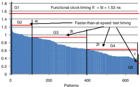
Functional clock timing tf = 5t = 1.53 ns G1
G2
G3
G4
G5 Faster-than-at-speed test timing 4t
3t
2t
t
Figure 2. pattern grouping based on pattern delay for faster-than- at-speed test timings (b15 benchmark).
slack of the sensitized paths.
The authors in [14] proposed a pattern selection method to reduce the pattern delay variation of the selected pattern set. The method uses a multiple-detect transition pattern set and statistical timing analysis technique to reduce the pattern delay variation. It can allow setting of a single faster and tighter test timing for the pattern set and result in high SDD detectability.
The technique proposed in [15] is based on test pattern grouping. The method groups a transition pattern set into multiple pattern sets which have almost equal pattern de- lay. Then, different pattern sets are applied at different test timings to detect SDDs. Figure 2 shows an exam- ple of the pattern grouping for the pattern set shown in Figure 1. In this example, we assumed five test timings with an interval of 20% of the functional clock timing (i.e., t,2t, 3t, 4t, 5t(=functional clock timing)). In addition, IR- drop effects in faster-than-at-speed testing were discussed in [15].
In [16], a transition pattern set is first copied as many times as the number of test timings used for a faster-than- at-speed test, and different test timings are assigned to the copied pattern sets. Since, the assigned test timing can be faster than the pattern delay, each pattern set is simulated at its assigned test timing and all the endpoints that do not
0 0.2 0.4 0.6 0.8 1 1.2 1.4 1.6 1.8
0 1000 2000 3000
pattern w/o endpoint masking pattern w endpoint masking
Patterns Max. Delay [ns]
Functional clock timing tf = 5t = 1.53 ns G1
G2
G3
G4
G5 Faster-than-at-speed test timing 4t
3t
2t
t
Figure 3. Copied pattern sets with endpoint masking for faster- than-at-speed test timings (b15 benchmark).
Slack [ns]
#Occurrence
0 1000 2000 3000 4000 5000
0 0.2 0.4 0.6 0.8 1 1.2 1.4 1.6
transition timing-aware
pattern grouping + faster-than-at-speed copied pattern sets + faster-than-at-speed
Figure 4. Minimum slack distributions for detectable faults by transition, timing-aware and two faster-than-at-speed test sets (b15 benchmark).
meet the required speed are masked by “don’t care”, re- ferred to as endpoint masking, to avoid any timing failure. The authors also discussed the hazard-free pattern genera- tion for faster-than-at-speed test. Figure 3 shows an exam- ple of the copied pattern sets with endpoint masking for the pattern set shown in Figure 1. In this example, we also as- sumed the five test timings with an interval of 20% of the functional clock timing.
Figure 4 compares the slack distributions of detectable faults by the above mentioned approaches. It shows that more faults are activated through the paths with less slack by adopting the faster-than-at-speed test approaches. In particular, the method using copied test sets with endpoint masking [16] can reduce the slack significantly compared to the method using pattern grouping based on pattern de- lay [15]. However, obviously, the major drawback of the approach using copied sets is the extremely large pattern count.
1.2 Contribution
In this paper, we present a novel framework for faster- than-at-speed testing to screen SDDs. The proposed method uses a transition fault test pattern set (post-ATPG approach) to avoid time-consuming ATPG and assumes a set of test
timings which can be used for faster-than-at-speed test is given. The proposed method then creates multiple copies of each pattern and assigns different test timings to them. However, in contrast to [16], when we create multiple copies of a pattern, we perform a detailed analysis of the active faults and their sensitized path delays in the pattern. The analysis can tell us the most effective pattern and test timing for each fault in terms of slack size and reduce the total pattern count significantly compared to [16] without losing the transition fault coverage.
Besides the minimum slack for a fault, the sensitized path delay itself is another important measure to evaluate the detectability of SDDs. Even though the above proposed method can minimize the slack significantly, it might also reduce the sensitized path delay since shorter paths can be used to reduce the slack in the faster-than-at-speed test with endpoint masking. Therefore, we also present a method to maximize the sensitized path delay for each fault while keeping the slack in a certain range. For this purpose, we in- troduce a user-specified slack threshold span slackth to de- fine the acceptable slack size and maximize the sensitized path delay under the constraint, instead of minimizing the slack. The idea using slackthcan be also used to further re- duce the total pattern count, instead of maximizing the sen- sitized path delay. Experimental results for larger ITC’99 benchmark circuits show the effectiveness of the proposed methods in terms of average slack and sensitized path de- lay among the active faults, statistical delay quality level (SDQL) [17] and pattern count.
The rest of the paper is organized as follows. Section 2 explains the method to minimize the slack using multiple faster-than-at-speed test timings while preventing a large in- crease in pattern count. The extension to maximize sensi- tize path delay and minimize pattern count under slack size constraint is discussed in Section 3. Experimental results are shown in Section 4. Finally, Section 5 concludes this paper.
2 Proposed Method to Minimize Slack 2.1 Overview
In this section, we discuss a problem to generate a pattern set for faster-than-at-speed testing to increase the detectabil- ity of SDDs. In this work, we use a transition fault test pat- tern set I to avoid time-consuming timing-aware ATPG and assume that a set of test timings T which can be used for the faster-than-at-speed test is given. We then focus on the generation of a faster-than-at-speed test pattern set IFT ASus- ing I and T . Here, the generation of a faster-than-at-speed test pattern is to (1) select a pattern i ∈ I, (2) assign a test timing t ∈ T to i and (3) create an endpoint mask m that invalidates all the active endpoints with larger delay than tby “don’t care” to avoid any timing failure. The gener- ated faster-than-at-speed pattern iFT AS is represented by 3-
FF1
FF2
FF3
FF4
FF5
FF6
x
x
x
f1
f2
f3
5ns
4ns
4ns 5ns 8ns
Test Timing: 9ns (no mask) Fault Endpoint Delay Slack
f1 FF4 5ns 4ns f2 FF4 8ns 1ns f3 FF4 5ns 4ns
Test Timing: 6ns (mask FF4) Fault Endpoint Delay Slack
f1 masked - - f2 FF5 4ns 2ns f3 FF6 4ns 2ns
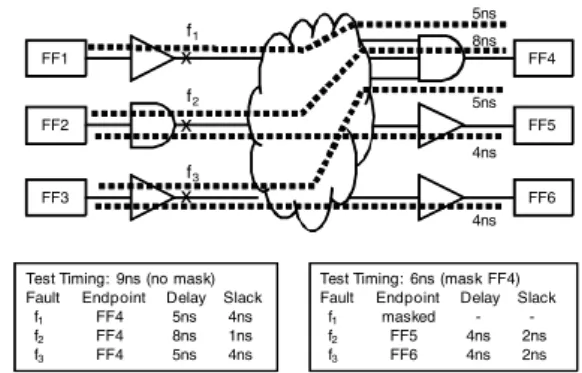
Figure 5. Active fault-endpoint pairs and endpoint masking.
tuple (i, t, m). The faster-than-at-speed test pattern genera- tion problem we consider in this section is formally defined as follows.
Definition 1 Pmin slack: Given a circuit, a test pattern set I, a set of transition faults F detected by I and a set of test tim- ings T , create a faster-than-at-speed test pattern set IFT AS so that (i) the transition fault coverage remains the same and (ii) slack( f ) for each f ∈ F is minimized, where slack( f ) is the minimum slack for fault f achieved by IFT AS.
A simple solution for this problem is the method pro- posed in [16]. It creates |T | copies of I and assigns a test timing tj ∈ T to all patterns in the j th copy. Each pattern is then simulated at its assigned test timing and an endpoint mask is created. Since it is enough for a fault to be detected at least once in the final pattern set, we can reduce the pat- tern count by selecting only the most effective pattern for each fault. In order for that, we perform a detailed path de- lay analysis for each pattern i ∈ I, which will be explained in the next subsection. The analysis gives us the information about the active faults, active endpoints and their sensitized path delays in each pattern, and allows us to reduce the pat- tern count while preserving the transition fault coverage and the slack size for the faults in F.
2.2 Sensitized Path Delay Analysis
The basic strategy in this work is to create multiple copies of a pattern and assign different faster-than-at-speed test timings to them. In this strategy, the shorter paths than the pattern delay (the maximum sensitized path delay in the pattern) might be used to reduce the slack with endpoint masking (i.e., all the active endpoints that do not meet the required speed are masked by “don’t care”). The endpoint masking can invalidate the sensitized paths with larger de- lay than the test timing intentionally. However, at the same time, it invalidates some of the sensitized paths with smaller delay than the test timing accidentally.
Figure 5 shows an example of sensitized paths and an endpoint masking. This example includes three faults and
Active Fault-Endpoint Pairs Delay [ns]
0 0.2 0.4 0.6 0.8 1 1.2 1.4 1.6 1.8
0 500 1000 1500 2000
Figure 6. Maximum sensitized path delay distribution of active fault-endpoint pairs in a single transition fault test pattern (pat- tern 498 in b15 benchmark).
Active Endpoints Delay [ns]
0 0.2 0.4 0.6 0.8 1 1.2 1.4 1.6 1.8
0 10 20 30 40 50 60 70
not masked masked
Faster-than-at-speed test timing tj
Figure 7. Sorted active endpoints for a single transition fault test pattern (pattern 498 in b15 benchmark).
five sensitized paths. When the test timing is 9 ns, no end- point needs to be masked at all and the faults are detected through the maximum sensitized paths, which are repre- sented by a fault and endpoint pair, referred to as active fault-endpoint pair, as shown in the bottom-left of the fig- ure. On the other hand, when the test timing is 6 ns, we need to mask FF4 to invalidate the active fault-endpoint pair ( f2,FF4), and the mask also invalidates the fault-endpoint pairs ( f1,FF4) and ( f3,FF4) accidentally. This makes f1 undetectable in the timing while f2and f3are still detectable at different endpoint with different delay and slack as shown in the bottom-right of the figure. In this example, only f3
can obtain the reduction in slack size.
Therefore, in this work, we analyze the active faults, ac- tive endpoint and the maximum sensitized path delay for each active fault-endpoint pair in each pattern. Once they are calculated, we can create the endpoint mask for any faster-than-at-speed test timing and obtain the maximum sensitized path delay and the minimum slack for all active faults under the test timing. Figure 6 shows the maximum sensitized path delay distribution of active fault-endpoint pairs (2,432 pairs in this example) in a single launch-off- capture transition fault test pattern for b15 benchmark. In this example, 263 faults are activated and the errors are
0 0.2 0.4 0.6 0.8 1 1.2 1.4 1.6 1.8
0 500 1000 1500 2000
not masked masked(intentional) masked(accidental)
Active Fault-Endpoint Pairs Delay [ns]
Faster-than-at-speed test timing tj
Figure 8. Sorted active fault-endpoint pairs for a single transition fault test pattern (pattern 498 in b15 benchmark).
1: Set IFT AS= φ;
2: Set slackminf = ∞ for all fault f ∈ F; 3: for alltest pattern i ∈ I do
4: for allactive fault-endpoint pair pf ,e(endpoint e for fault f ) do 5: Calculate maximum sensitized path delay di, f ,e;
6: end for
7: for alltest timing t ∈ T do
8: Create mask m that masks all the endpoints with larger delay than t; 9: Create faster-than-at-speed test icurFT AS=(i, t, m);
10: for allactive fault-endpoint pair pf ,edo
11: if eis not masked and slack(di, f ,e,t) < slackminf then 12: Update slackminf =slack(di, f ,e,t);
13: Update iFT ASf =icurFT AS;
14: end if
15: end for
16: end for 17:end for 18:for allfault f do 19: IFT AS=IFT AS∪ {ifFT AS}; 20:end for
Figure 9. The proposed flow forPmin slack.
propagated to 73 endpoints. Figures 7 and 8 show the sorted active endpoints and the sorted active fault-endpoint pairs based on the maximum sensitized path delay. For the given test timing tj, we can know that the active endpoints shown in red need to be masked. Consequently, all the sensitized paths for active fault-endpoint pairs with larger delay than tjshown in red are intentionally masked while some of the sensitized paths with smaller delay are accidentally masked. From the analysis, we can obtain the active faults, their maximum sensitized path delay and minimum slack under the endpoint mask for the test timing tj.
2.3 Flow
Figure 9 summarizes the flow of the proposed method to minimize the slack for each fault f ∈ F. We start with the initialization of the faster-than-at-speed test set IFT AS (line 1) and the current minimum slack slackminf for each fault f (line 2). Then, the following process is repeated for each test pattern i ∈ I, (from line 3 to 17). We first perform the path delay analysis explained in Section 2.2 to calcu- late the maximum sensitized path delay di, f ,efor each active fault-endpoint pair in pattern i (from line 4 to 6). From the path delay analysis, an endpoint mask m and a faster-than-
at-speed test icurFT ASare also created for each test timing t ∈ T (line 8 and 9). We then check all the active fault-endpoint pair pf ,ein pattern i. If the endpoint e is not masked by m and the slack of the maximum sensitized path delay di, f ,e
relative to the test timing t, referred to as slack(di, f ,e,t) in Figure 9, is less than the current minimum slack slackminf of fault f (line 11), we update the current minimum slack (line 12) and the most effective pattern iFT ASf for f (line 13) to minimize the slack. The final faster-than-at-speed test set IFT AS is the union of the most effective pattern iFT ASf for
each fault f (from line 18 to 20).
The sensitized path delay analysis explained in Section 2.2 is the most time consuming part in the proposed flow. For the same example used in the previous section, b15 benchmark (9k gates circuit with 417 FFs and 663 patterns) is analyzed in about half an hour. Even for b19 (144k gates with 6,042 FFs and 2,144 patterns) which is the largest cir- cuit in ITC’99 benchmark, the CPU runtime is about 30 hours.
3 Extension to Maximize Sensitized Path Delay and Minimize Pattern Count
3.1 Problem Formulation
In the previous section, we discussed the problem to min- imize the slack of the detectable faults by the given test pat- tern set and presented a method to solve the problem. In this section, we consider the problem to constrain the slack of the detectable faults to be in a certain range, referred to as slack threshold span slackth. Different from the case to minimize the slack, multiple faster-than-at-speed test pat- terns can satisfy the constraint for each fault, and this allows us to have another objective for the final pattern selection. In this paper, we consider two different objectives: (1) max- imize sensitized path delay and (2) minimize pattern count.
(Maximize Sensitized Path Delay): Besides the slack of the sensitized path for a fault, the sensitized path delay itself is another important measure to evaluate the detectability of SDDs. However, the shorter paths might be used to re- duce the slack in the faster-than-at-speed test with endpoint masking. Therefore, we consider the following problem to maximize the sensitized path delay for each fault while keeping the slack in a certain range.
Definition 2 Pmax delay: Given a circuit, a test pattern set I, a set of transition faults F detected by I, a set of test timings T and a slack threshold span slackth, cre- ate a faster-than-at-speed test pattern set IFT AS so that (i) the transition fault coverage remains the same, (ii)
!
f ∈F{max (slack( f ), slackth) − slackth} is minimized and (iii) delay( f ) for each f ∈ F is maximized subject to (i) and (ii), where slack( f ) and delay( f ) are the minimum slack
and maximum sensitized path delay for fault f achieved by IFT AS, respectively.
(Minimize Pattern Count): On the other hand, the large pat- tern count is a major drawback of the methods which create multiple copies of a pattern and assign different test timings to them. Even though the method presented in the previous section can reduce the pattern count significantly, we con- sider the following problem to further reduce the pattern count while keeping the slack in a certain range.
Definition 3 Pmin test: Given a circuit, a test pattern set I, a set of transition faults F detected by I, a set of test timings Tand a slack threshold span slackth, create a faster-than-at- speed test pattern set If so that (i) the transition fault cov- erage remains the same, (ii) !f{max (slack( f ), slackth) − slackth} is minimized and (iii) the pattern count is mini- mized subject to (i) and (ii), where slack( f ) is the minimum slack for fault f achieved by IFT AS.
3.2 Flow
Figure 10 summarizes the proposed flow for Pmax delay
and Pmin test which is similar to the flow shown in Figure 9. The difference is to use a variable statef for each fault f to represent the current detection state for f (line 3). It is S UCCES S if we have found at least one faster-than- at-speed test pattern that satisfies the slack constraint (i.e., slack( f ) should be less than slackth). Otherwise, it is FAIL. If statef is S UCCES S and we found a faster-than-at-speed test pattern (line 13), it is then added to the candidate test set IFT ASf for f (line 14). If statef is FAIL and we found a faster-than-at-speed test pattern (line 15), the state is then updated to S UCCES S (line 16) and the candidate test set IFT ASf for f is initialized by the pattern (line 17). Otherwise, only when we found a faster-than-at-speed test pattern that has less slack than the current minimum slack slackminf for f , the candidate test set IFT ASf is updated by the pattern (from line 18 to 20). Finally, for each fault f , we select a pattern from the candidate test set IFT ASf (line from 26 to 31). For the problem Pmax delay, we select a test pattern so that the sensitized path delay for f is maximized (line 28). On the other hand, for the problem Pmin test, we select a pattern so that the total pattern count in IFT ASf is minimized (line 29).
In this paper, we used a simple greedy selection method for minimizing the total pattern count. We first select a pattern from the set of all the candidate patterns S (=
"
f ∈FI f
FT AS) so that the number of newly detected faults is maximized and add it to IFT AS. Then, the candidate test set to which the selected pattern belongs is removed from S . This process is repeated until S becomes empty.
4 Experimental Results
In this section, we present experimental results using several ITC’99 benchmark circuits. The characteristics of
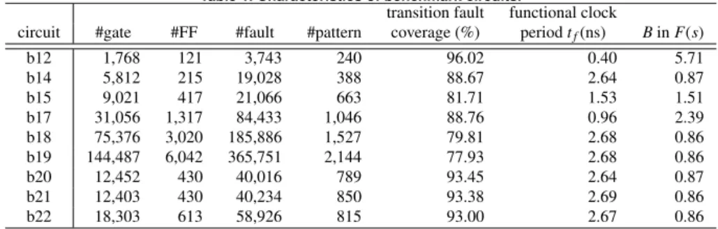
Table 1. Characteristics of benchmark circuits.
transition fault functional clock
circuit #gate #FF #fault #pattern coverage (%) period tf(ns) Bin F(s)
b12 1,768 121 3,743 240 96.02 0.40 5.71
b14 5,812 215 19,028 388 88.67 2.64 0.87
b15 9,021 417 21,066 663 81.71 1.53 1.51
b17 31,056 1,317 84,433 1,046 88.76 0.96 2.39
b18 75,376 3,020 185,886 1,527 79.81 2.68 0.86
b19 144,487 6,042 365,751 2,144 77.93 2.68 0.86
b20 12,452 430 40,016 789 93.45 2.64 0.87
b21 12,403 430 40,234 850 93.38 2.69 0.86
b22 18,303 613 58,926 815 93.00 2.67 0.86
1:Set IFT AS= φ;
2:Set slackminf = ∞ for all fault f ∈ F; 3:Set statef=FAILfor all fault f ∈ F; 4:for alltest pattern i ∈ I do
5: for allactive fault-endpoint pair pf ,e(endpoint e for fault f ) do 6: Calculate maximum sensitized path delay di, f ,e;
7: end for
8: for alltest timing tjdo
9: Create mask m that masks all the endpoints with larger delay than t; 10: Create faster-than-at-speed test icurFT AS=(i, t, m);
11: for allactive fault-endpoint pair pf ,edo 12: if eis not masked then
13: if statef=S UCCES S and slack(di, f ,e,t) < slackththen 14: Update candidate test set IFT ASf =IFT ASf ∪ {icurFT AS}; 15: else if statef=FAIL and slack(di, f ,e,t) < slackththen
16: Set statef=S UCCES S;
17: Update candidate test set IFT ASf ={icurFT AS}; 18: else if statef=FAIL and slack(di, f ,e,t) < slackminf then 19: Update candidate test set IFT ASf ={icurFT AS}; 20: Update slackminf =slack(di, f ,e,t);
21: end if
22: end if
23: end for
24: end for 25:end for 26:for allfault f do
27: Select a pattern iFT ASf from IFT ASf so that 28: (option1: Pmax delay) delay( f ) is maximized; 29: (option2: Pmin test) the total pattern count is minimized; 30: Set IFT AS=IFT AS∪ {iFT ASf };
31:end for
Figure 10. The proposed flow forPmax delayandPmin test.
the circuits used in the experiments are summarized in Ta- ble 1.
In the experiments, we compare the following six meth- ods to evaluate the effectiveness of the proposed meth- ods: original, pattern grouping, copied sets, proposed (min slack), proposed (max delay) and proposed (min test).
“original” denotes a transition fault test pattern set gener- ated by a commercial ATPG and it is used as the input pattern set to generate the faster-than-at-speed test set in the other five methods. “pattern grouping” represents the method based on test pattern grouping presented in [15] and
“copied sets” represents the method using multiple copies of the original test set with different test timings proposed in [16]. However, please note that the methods are not ex- actly the same as those proposed in [15, 16] and only the ba- sic concepts were implemented by us to evaluate the effec- tiveness of the proposed methods. The last three methods
“proposed (min slack)”, “proposed (max delay)” and “pro-
posed (min test)” are the proposed methods for the problems Pmin slack, Pmax delayand Pmin test, respectively.
In order to evaluate the detectability of SDDs, we use the following three criteria: (1) average of the minimum slack of faults, (2) average of the maximum sensitized path delay of faults and (3) statistical delay quality level (SDQL). The SDQL for a given test set is the amount of delay defects that should be detected but cannot be detected by the test set [17], and we used the following definition for faster- than-at-speed test:
S DQL =#
f ∈N
$ slack( f ) 0
F(s) ds (1)
where N is the total number of faults and F(s) is a delay defect distribution function. In all the experiments, we use the exponential function F(s) = e−Bsand set B to the val- ues shown in the column “B in F(s)” in Table 1. We also evaluate the total pattern count used in the methods.
Table 2 summarizes the results when five test timings (T = {t, 2t, 3t, 4t, 5t (= functional clock period tf)}) are used for the faster-than-at-speed test approaches, and Ta- ble 3 summarizes the results when ten test timings (T = {t,2t, ..., 10t (= functional clock period tf)}) are used. For both cases, the slack threshold span slackth used in “pro- posed (max delay)” and “proposed (min test)” was set to t (i.e., the interval of the fastest test timing). The columns
“diff (%)“ in the tables denote the relative difference to
“original”.
In terms of the detectability of SDDs, “copied sets” can provide the best results among them in all the cases. In case of |T | = 5, it can obtain 67% and 87% reduction on average in SDQL and average of the minimum slack, respectively while preserving the maximum sensitized path delay of the original test set. In case of |T | = 10, the reduction on av- erage is increased up to 73% in SDQL and 91% in average of the minimum slack. However, it incurred a significant increase in pattern count. The increase in pattern count is up to 400% and 900% (i.e., 5X and 10X) when |T | = 5 and
|T | =10, respectively.
“proposed (min slack)” can also achieve exactly the same reduction in SDQL and average of the minimum slack as
0 1000 2000 3000 4000 5000 6000
0 0.2 0.4 0.6 0.8 1 1.2 1.4 1.6
original (transition) proposed (min slack) proposed (max delay) proposed (min test)
Slack [ns]
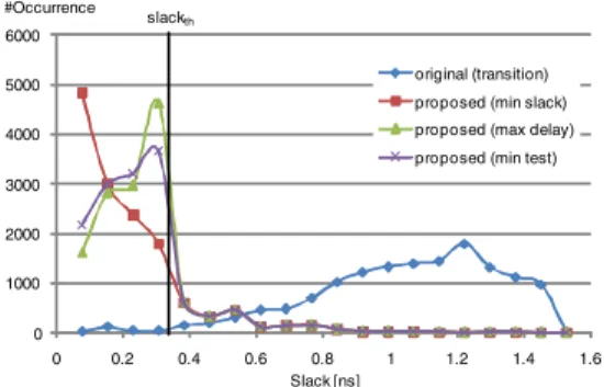
#Occurrence slackth
Figure 11. Minimum slack distributions for detectable faults by transition fault pattern set and proposed methods(b15 bench- mark).
“copied sets” while preventing the large increase in pattern count. The increase in pattern count is 101% on average when |T | = 5 and 183% on average even when |T | = 10. The results show that “proposed (min slack)” effectively min- imizes the slack compared to “copied sets”. However, it decreased the sensitized path delay. The faults in “proposed (min slack)” were sensitized through around 14% shorter paths compared to “original” and “copied sets” on average. The decrease in sensitized path delay can be alleviated down to 1.6% on average in “proposed (max delay)” by sac- rificing SDQL 8% and average of the minimum slack 6% when |T | = 5. Similarly, by sacrificing SDQL and average of the minimum slack, “proposed (min test)” can further re- duce the increase in pattern count down to 80% and 140% on average when |T | = 5 and |T | = 10, respectively. Fig- ure 11 compares the minimum slack distributions of faults in “original” and the proposed methods. The number of faults with slack less than the slack threshold span slackthis exactly the same in the three proposed methods. However,
“proposed (max delay)” and “proposed (min test)” tried to maximize the sensitized path delay and minimize the pat- tern count under the slack constraint, respectively. The re- sults show that constraining the slack to be in a certain range instead of minimizing can effectively work to maximize the sensitized path delay and further reduce the pattern count. 5 Conclusion
In this paper, we have presented a novel framework for faster-than-at-speed testing to increase test quality and in- field reliability. The proposed method is based on the de- tailed analysis of the maximum sensitized path delay for active fault-endpoint pairs in each pattern. Because of the analysis, we can minimize the slack for the detectable faults while preventing a large increase in pattern count even though the proposed method uses multiple faster-than-at- speed test timings for each pattern. We also have presented two methods to maximize the sensitized path delay and fur- ther reduce the pattern count under a constraint on the al- lowable slack size, instead of minimizing the slack. Ex-
perimental results for ITC’99 benchmark circuits showed that the proposed methods can reduce the slack significantly while preserving the sensitized path delay and preventing the pattern count increase effectively.
Acknowledgments
This work was supported in part by Japan Society for the Pro- motion of Science (JSPS) under Grants-in-Aid for Scientific Research (B)(No.20300018) and Young Scientists (B)(No.21700059).
References
[1] N. Ahmed, M. Tehranipoor, and V. Jayaram, “Timing-based delay test for screening small delay defects,” in Proc. Design Automation Conference, pp. 320–325, July 2006.
[2] X. Lin, K. H. Tsai, C. Wang, M. Kassab, J. Rajski, T. Kobayashi, R. Klingenberg, Y. Sato, S. Hamada, and T. Aikyo, “Timing-aware ATPG for high quality at-speed testing of small delay defects,” in Proc. Asian Test Symposium, pp. 139–146, Nov. 2006.
[3] Y. Li, S. Makar, and S. Mitra, “CASP: Concurrent autonomous chip self-test using stored test patterns,” in Proc. Design, Automation, and Test in Europe, pp. 885–890, Mar. 2008.
[4] H. Inoue, Y. Li, and S. Mitra, “VAST: Virtualization-assisted concur- rent autonomous self-test,” in Proc. International Test Conference, pp. 1–10, Oct. 2008.
[5] Y. Sato, S. Kajihara, Y. Miura, T. Yoneda, S. Ohtake, M. Inoue, and H. Fujiwara, “A circuit failure prediction mechanism (DART) for high field reliability,” in Proc. International Conference on ASIC, pp. 581–584, Oct. 2009.
[6] M. Agarwal, B. C. Paul, M. Zhang, and S. Mitra, “Circuit failure prediction and its application to transistor aging,” in Proc. VLSI Test Symposium, pp. 277–284, May 2007.
[7] T. W. Chen, K. Kim, Y. M. Kim, and S. Mitra, “Gate-oxide early failure prediction,” in Proc. VLSI Test Symposium, pp. 111–118, May 2008.
[8] Synopsys, TetraMAX ATPG User Guide, Version C-2009.06-SP2, September 2009.
[9] A. Uzzaman, M. Tegethoff, B. Li, K. M. Cauley, S. Hamada, and Y. Sato, “Not all delay tests are the same - SDQL model shows true- time,” in Proc. Asian Test Symposium, pp. 147–152, Nov. 2006. [10] M. Yilmaz, K. Chakrabarty, and M. Tehranipoor, “Test-pattern grad-
ing and pattern selection for small-delay defects,” in Proc. VLSI Test Symposium, pp. 233–239, May 2008.
[11] Cadence Inc., Encounter True-Time Test ATPG, 2006.
[12] R. Putman and R. Gawde, “Enhanced timing-based transition de- lay testing for small delay defects,” in Proc. VLSI Test Symposium, pp. 336–342, Apr. 2006.
[13] X.Fu, H. Li, and X. Li, “On selection of testable paths with specified lengths for faster-than-at-speed testing,” in Proc. Asian Test Sympo- sium, pp. 45–48, Dec. 2010.
[14] B. N. Lee, L. C. Wang, and M. S. Abadir, “Reducing pattern delay variations for screening frequency dependent defects,” in Proc. VLSI Test Symposium, pp. 153–160, Apr. 2005.
[15] N. Ahmed and M. Tehranipoor, “A novel faster-than-at-speed transition-delay test method considering IR-drop effects,” IEEE Trans. Computer-Aided Design of Integrated Circuits and Systems, vol. 28, pp. 1573–1582, Oct. 2009.
[16] B. Kruseman, A. K. Majhi, G. Gronthoud, and S. Eichenberger, “On hazard-free patterns for fine-delay fault testing,” in Proc. Interna- tional Test Conference, pp. 213–222, Oct. 2004.
[17] Y. Sato, S. Hamada, T. Maeda, A. Takatori, and S. Kajihara, “Evalu- ation of the statistical delay quality model,” in Proc. Asian and South Pacific Design Automation Conference, pp. 305–310, Jan. 2005.
Table 2. Results: number of test timings|T | =5andslackth=f unctional clock period/|T |.
circuit method SDQL diff (%) ave. min slack (ns) diff (%) ave. max delay (ns) diff (%) #pattern diff (%)
original 386 - 0.160 - 0.240 - 240 -
pattern grouping 280 -27.67 0.102 -36.58 0.240 0.00 240 0.00
b12 copied sets 126 -67.40 0.034 -79.03 0.240 0.00 1,200 400.00
proposed (min slack) 126 -67.40 0.034 -79.03 0.227 -5.41 500 108.33
proposed (max delay) 157 -59.49 0.044 -72.65 0.239 -0.28 526 119.17
proposed (min test) 157 -59.39 0.044 -72.61 0.224 -6.68 444 85.00
original 18,581 - 2.064 - 0.576 - 388 -
pattern grouping 8,029 -56.79 0.407 -80.28 0.576 0.00 388 0.00
b14 copied sets 5,129 -72.40 0.185 -91.06 0.576 0.00 1,940 400.00
proposed (min slack) 5,129 -72.40 0.185 -91.06 0.487 -15.36 630 62.37
proposed (max delay) 7,017 -62.23 0.321 -84.43 0.563 -2.21 645 66.24
proposed (min test) 7,237 -61.05 0.339 -83.58 0.500 -13.21 557 43.56
original 11,187 - 0.998 - 0.532 - 663 -
pattern grouping 6,781 -39.38 0.343 -65.68 0.532 0.00 663 0.00
b15 copied sets 4,820 -56.92 0.163 -83.66 0.532 0.00 3,315 400.00
proposed (min slack) 4,820 -56.92 0.163 -83.66 0.469 -11.84 1,130 70.44
proposed (max delay) 5,383 -51.88 0.203 -79.67 0.525 -1.22 1,158 74.66
proposed (min test) 5,439 -51.38 0.207 -79.23 0.467 -12.21 993 49.77
original 24,621 - 0.493 - 0.467 - 1,046 -
pattern grouping 19,364 -21.35 0.325 -34.18 0.467 0.00 1,046 0.00
b17 copied sets 10,130 -58.85 0.107 -78.24 0.467 0.00 5,230 400.00
proposed (min slack) 10,130 -58.85 0.107 -78.24 0.405 -13.28 3,470 231.74
proposed (max delay) 12,221 -50.36 0.141 -71.40 0.460 -1.50 3,621 246.18
proposed (min test) 12,300 -50.04 0.143 -71.11 0.406 -13.09 3,048 191.40
original 185,619 - 2.067 - 0.613 - 1,527 -
pattern grouping 115,850 -37.59 0.673 -67.42 0.613 0.00 1,527 0.00
b18 copied sets 71,977 -61.22 0.226 -89.05 0.613 0.00 7,635 400.00
proposed (min slack) 71,977 -61.22 0.226 -89.05 0.514 -16.10 3,167 107.40
proposed (max delay) 82,811 -55.39 0.315 -84.75 0.602 -1.79 3,387 121.81
proposed (min test) 86,958 -53.15 0.351 -83.02 0.538 -12.21 2,875 88.28
original 369,319 - 2.104 - 0.576 - 2,144 -
pattern grouping 232,537 -37.04 0.668 -68.26 0.576 0.00 2,144 0.00
b19 copied sets 148,361 -59.83 0.227 -89.22 0.576 0.00 10,720 400.00
proposed (min slack) 148,361 -59.83 0.227 -89.22 0.486 -15.67 4,292 100.19
proposed (max delay) 169,633 -54.07 0.318 -84.90 0.569 -1.21 4,648 116.79
proposed (min test) 178,697 -51.61 0.358 -82.97 0.510 -11.52 3,970 85.17
original 38,687 - 2.058 - 0.582 - 789 -
pattern grouping 16,229 -58.05 0.440 -78.61 0.582 0.00 789 0.00
b20 copied sets 9,157 -76.33 0.192 -90.65 0.582 0.00 3,945 400.00
proposed (min slack) 9,157 -76.33 0.192 -90.65 0.488 -16.12 1,358 72.12
proposed (max delay) 13,114 -66.10 0.321 -84.38 0.569 -2.27 1,379 74.78
proposed (min test) 14,092 -63.57 0.356 -82.68 0.507 -12.90 1,215 53.99
original 39,494 - 2.104 - 0.586 - 850 -
pattern grouping 16,222 -58.93 0.435 -79.33 0.586 0.00 850 0.00
b21 copied sets 8,653 -78.09 0.172 -91.82 0.586 0.00 4,250 400.00
proposed (min slack) 8,653 -78.09 0.172 -91.82 0.493 -15.92 1,405 65.29
proposed (max delay) 12,819 -67.54 0.308 -85.38 0.573 -2.15 1,431 68.35
proposed (min test) 13,807 -65.04 0.342 -83.75 0.509 -13.21 1,250 47.06
original 57,245 - 2.038 - 0.632 - 815 -
pattern grouping 25,400 -55.63 0.472 -76.82 0.632 0.00 815 0.00
b22 copied sets 12,652 -77.90 0.166 -91.85 0.632 0.00 4,075 400.00
proposed (min slack) 12,652 -77.90 0.166 -91.85 0.515 -18.56 1,577 93.50
proposed (max delay) 19,273 -66.33 0.312 -84.66 0.617 -2.37 1,614 98.04
proposed (min test) 21,066 -63.20 0.356 -82.54 0.536 -15.25 1,417 73.87
original 82,793 - 1.565 - 0.534 - 940 -
pattern grouping 48,966 -43.60 0.429 -65.24 0.534 0.00 940 0.00
ave copied sets 30,112 -67.66 0.164 -87.17 0.534 0.00 4,701 400.00
proposed (min slack) 30,112 -67.66 0.164 -87.17 0.454 -14.25 1,948 101.26
proposed (max delay) 35,825 -59.27 0.254 -81.36 0.524 -1.67 2,045 109.56
proposed (min test) 37,750 -57.60 0.277 -80.17 0.466 -12.25 1,752 79.79
Table 3. Results: number of test timings|T | =10andslackth=f unctional clock period/|T |.
circuit method SDQL diff (%) ave. min slack (ns) diff (%) ave. max delay (ns) diff (%) #pattern diff (%)
original 386 - 0.160 - 0.240 - 240 -
pattern grouping 248 -35.75 0.086 -46.35 0.240 0.00 240 0.00
b12 copied sets 81 -78.91 0.018 -88.77 0.240 0.00 2,400 900.00
proposed (min slack) 81 -78.91 0.018 -88.77 0.228 -5.15 650 170.83
proposed (max delay) 95 -75.30 0.022 -86.14 0.239 -0.38 681 183.75
proposed (min test) 96 -75.09 0.022 -85.99 0.224 -6.45 553 130.42
original 18,581 - 2.064 - 0.576 - 388 -
pattern grouping 6,127 -67.03 0.248 -87.98 0.576 0.00 388 0.00
b14 copied sets 4,300 -76.86 0.119 -94.22 0.576 0.00 3,880 900.00
proposed (min slack) 4,300 -76.86 0.119 -94.22 0.486 -15.68 756 94.85
proposed (max delay) 5,140 -72.34 0.174 -91.55 0.559 -2.96 760 95.88
proposed (min test) 5,319 -71.37 0.187 -90.96 0.489 -15.07 648 67.01
original 11,187 - 0.998 - 0.532 - 663 -
pattern grouping 6,065 -45.79 0.274 -72.53 0.532 0.00 663 0.00
b15 copied sets 4,039 -63.90 0.104 -89.58 0.532 0.00 6,630 900.00
proposed (min slack) 4,039 -63.90 0.104 -89.58 0.467 -12.19 1,526 130.17
proposed (max delay) 4,396 -60.71 0.127 -87.28 0.521 -1.97 1,528 130.47
proposed (min test) 4,385 -60.81 0.126 -87.35 0.462 -13.12 1,251 88.69
original 24,621 - 0.493 - 0.467 - 1,046 -
pattern grouping 18,059 -26.65 0.287 -41.87 0.467 0.00 1,046 0.00
b17 copied sets 8,324 -66.19 0.075 -84.80 0.467 0.00 10,460 900.00
proposed (min slack) 8,324 -66.19 0.075 -84.80 0.407 -12.79 5,344 410.90
proposed (max delay) 9,506 -61.39 0.092 -81.29 0.456 -2.26 5,553 430.88
proposed (min test) 9,467 -61.55 0.092 -81.41 0.405 -13.23 4,467 327.06
original 185,619 - 2.067 - 0.613 - 1,527 -
pattern grouping 101,796 -45.16 0.514 -75.13 0.613 0.00 1,527 0.00
b18 copied sets 63,520 -65.78 0.153 -92.59 0.613 0.00 15,270 900.00
proposed (min slack) 63,520 -65.78 0.153 -92.59 0.511 -16.58 5,138 236.48
proposed (max delay) 69,416 -62.60 0.197 -90.47 0.594 -3.00 5,383 252.52
proposed (min test) 70,008 -62.28 0.202 -90.24 0.508 -17.08 4,381 186.90
original 369,319 - 2.104 - 0.576 - 2,144 -
pattern grouping 206,992 -43.95 0.516 -75.46 0.576 0.00 2,144 0.00
b19 copied sets 131,182 -64.48 0.149 -92.90 0.576 0.00 21,440 900.00
proposed (min slack) 131,182 -64.48 0.149 -92.90 0.482 -16.23 7,012 227.05
proposed (max delay) 142,741 -61.35 0.194 -90.77 0.563 -2.17 7,418 245.99
proposed (min test) 144,178 -60.96 0.200 -90.49 0.480 -16.71 6,038 181.62
original 38,687 - 2.058 - 0.582 - 789 -
pattern grouping 11,510 -70.25 0.263 -87.21 0.582 0.00 789 0.00
b20 copied sets 7,212 -81.36 0.124 -93.99 0.582 0.00 7,890 900.00
proposed (min slack) 7,212 -81.36 0.124 -93.99 0.490 -15.79 1,681 113.05
proposed (max delay) 8,859 -77.10 0.172 -91.62 0.564 -3.18 1,656 109.89
proposed (min test) 9,464 -75.54 0.191 -90.72 0.493 -15.24 1,426 80.74
original 39,494 - 2.104 - 0.586 - 850 -
pattern grouping 11,533 -70.80 0.259 -87.70 0.586 0.00 850 0.00
b21 copied sets 7,141 -81.92 0.118 -94.38 0.586 0.00 8,500 900.00
proposed (min slack) 7,141 -81.92 0.118 -94.38 0.496 -15.28 1,714 101.65
proposed (max delay) 8,964 -77.30 0.172 -91.83 0.568 -3.00 1,688 98.59
proposed (min test) 9,533 -75.86 0.189 -91.00 0.489 -16.55 1,442 69.65
original 57,245 - 2.038 - 0.632 - 815 -
pattern grouping 18,834 -67.10 0.303 -85.12 0.632 0.00 815 0.00
b22 copied sets 10,049 -82.45 0.105 -94.86 0.632 0.00 8,150 900.00
proposed (min slack) 10,049 -82.45 0.105 -94.86 0.518 -18.05 2,173 166.63
proposed (max delay) 12,863 -77.53 0.161 -92.08 0.613 -3.14 2,171 166.38
proposed (min test) 13,709 -76.05 0.179 -91.22 0.511 -19.28 1,798 120.61
original 82,793 - 1.565 - 0.534 - 940 -
pattern grouping 42,351 -52.50 0.306 -73.26 0.534 0.00 940 0.00
ave copied sets 26,205 -73.54 0.107 -91.79 0.534 0.00 9,402 900.00
proposed (min slack) 26,205 -73.54 0.107 -91.79 0.454 -14.19 2,888 183.51
proposed (max delay) 29,109 -69.51 0.146 -89.23 0.520 -2.45 2,982 190.48
proposed (min test) 29,573 -68.84 0.154 -88.82 0.451 -14.75 2,445 139.19